Dakota Digital BIM-13-2 User manual

[1] MAN #650505D
BIM-13-2
Bus Interface Module for Air/Fuel ratio
(Requires a wide band air/fuel controller with a voltage output)
•This BIM-13-2 works off a single wire input to monitor the air/fuel ratio output from a wide band air/fuel controller
with an analog voltage output.
oCannot read direct from an air/fuel sensor.
•The BIM-13-2 is programmable to provide either an air/fuel ratio display or a lambda display.
•The BIM-13-2 can be programmed to work with different scaling values of a voltage between 0 –5 volts.
•There are two interface (I/O) ports on the module.
oEither one can be connected to the instrument system or to another BIM module
•Do not connect the I/O port to anything other than a Dakota Digital control box or another BIM.
•The BIM-13-2 should be mounted in the vehicle cabin, NOT in the engine bay.
Table of Contents:
Displays, Specs, Configuration Values
Page 2
VFD, and VFDX Setup
Page 3
VHX Setup
Page 4
HDX / RTX Setup
Page 5
Changing ID Channel / Troubleshooting
Page 6
Service and Warranty
Page 8
If needed, contact Dakota Digital sales to order.

[2] MAN #650505D
System Displays of Air/Fuel:
VFD3 –Tap SW2 (II) until A-F is displayed. Wait a second, and AF plus the value will display.
VFD3X –Tap SW1 (I) to bring up the tach bar screen. Then tap SW2 (II) to display AF at the lower half.
VHX –Tap SW2 (II) to display AIR / FUEL.
HDX/RTX –
•Use the app to configure the group screen under “DISPLAYS” to have BIM CH 16 display A/F.
•Tap the right switch on the display, or SW2 (II), to display the group with A/F.
VFD3 A-F
VFD3X
VHX
HDX/RTX
Air/Fuel
AF xx.x
1 2 3 4 5 6 7 8
AF xx.x
AIR / FUEL
xx.x
xx.x A/F
Lambda
AF x.xx
1 2 3 4 5 6 7 8
AF x.xx
AIR / FUEL
x.xx
x.xx A/F
*Display will not say ‘Lambda’. You must know you configured the BIM-13-2 to read the Lambda scale.
Specs for each input mode are:
Mode
Range
Resolution
(WARN LO) 0V setting
(WARN HI) 5V setting
Air / Fuel
A-F ratio
0 –5.00 V
0.1
00.0 –12.6
4.4 –74.0
Air / Fuel
Lambda
0 –5.00 V
0.01
0.00 –0.63
1.00 –5.00
To change between Air / Fuel and Lambda readings:
•Turn the key on so the instrument system and BIM-13-2 are powered.
•Press and hold the setup/status switch on the BIM-13-2. The status light will slowly flash red and green.
•After about 10 seconds the status light will begin flashing red and green rapidly. Release the switch.
•The reading will now be changed.
Configuring LO and HI settings for popular analog output signals:
Consult your wide band air fuel installation and operation manual for details on the type of analog output provided.
Set the BIM-13-2 to A/F or Lambda prior to setting upper and lower limits.
The unit will not remember both ranges
❖Setting the Warn LO and Warn HI will configure the output reading.
Output Type
Output Reading vs. Voltage
A/F LO
A/F HI
Lambda LO
Lambda HI
10 to 20
10 = 1.0V, 20 = 2.0V
0.0
50.0
0.00
3.40
0 to 50
0 = 0.0V, 50 = 5.0V
0.0
50.0
0.00
3.40
9 to 16
9 = 0.0V, 16 = 5.0V
9.0
16.0
0.61
1.10
7.35 to 22.39
7.35 = 0.0V, 22.39 = 5.0V
7.4
22.4
0.50
1.50
Lambda
0.5 = 0.5V, 1.5 = 1.5V
0.0
74.0
0.00
5.00
8.5 to 18
8.5 = 0.5V, 18 = 4.5V
7.4
19.2
0.50
1.30
**Note**
•Different fuel types will require different scaling values for the air fuel ratios.
•Consult your wide band air fuel installation and operation manual for more details on using different fuel types.
•The BIM-13-2 does not have warning indications.
•Setting the above values in the VFD, VHX, HDX, or RTX will only configure the proper values.
When setting limits for Lambda values, the numbers will change in 0.10 increments for low and high.
When setting limits for Air/Fuel, the incrementing will vary on the range:
•Warn LO values will change in 0.2 increments.
•Warn HI:
oBetween 4.4 and 10.8 the value will change in 0.2 increments
oBetween 10.8 to 23.6 the value will change in 0.4 increments
oBetween 23.6 to 74.0 the value will change in 0.8 increments

[3] MAN #650505D
VFD3, and VFD3X setup:
**Only VFD3 & VFD3X systems with a plastic case can support BIMs**
✓Ensure all desired BIM units are connected to the control box with the appropriate data cables.
1. Hold the SW1 (I) switch for the VFD3 control box while turning the key on.
a. The speed display will show “” and the message display will show SETUP.
2. Release SW1. The displays should show “”and SPEED, respectively.
3. Tap SW1 (I) until “and BIM is displayed.
4. Press and hold SW1 (I) until “-“ and SCAN x are displayed,
a. “x” = number of BIM channels found
b. If SCAN 0 is displayed, check connections of the BIM-13-2 to VFD3 control box
i. If multiple BIM units are installed, follow the “Change ID” steps above to correct conflicts
ii. Then enter setup again and begin the BIM setup process again
c. The BIM-01-2 OBDII has no channels and will not be found
5. Release SW1. The displays will show “ and SCAN
a. Scanning is not required if SCAN x equals the number BIM modules found
b. If SCAN x does not equal the number of BIMs, follow the “Change ID” steps above to correct conflicts
i. Some BIMs can use more than one channel (BIM-19 = 5, BIM-22 = 4)
ii. Then enter setup again and begin the BIM setup process again
6. Otherwise, press and release SW1 (I) until “ and SETUP are shown.
7. Press and hold SW1 (I) until “ – “ and SETUP is displayed.
8. Release SW 1 (I).
a. The speed should display the default channel ID as “”.
b. The message center will display the label of A-F.
c. With multiple BIM modules, tap SW 1 (I) until “” and the label (a-f) are displayed.
9. Press and hold SW1 (I), speed will display “-“ and the message display will show LABEL.
a. Label cannot be changed and will only display AF and the value.
10. Release SW1 (I). Speed will display “”and the message displays AF.
11. Press and hold SW1 to save the label, and “ –“ and WARN is displayed.
12. Release SW1. The message display will show Lfollowed by the current LO warning point.
13. Tap SW1 to change the high warning point to the desired value, (refer to pg. 2 and controller data).
14. Press and hold SW1 (I) until “ –“ and L xxx are displayed.
15. Release SW1. The message display will show Hfollowed by the current HI warning point.
16. Tap SW1 to change the high warning point to the desired value, (refer to pg. 2 and controller data).
17. Press and hold SW1 (I) until “ –“ and H xxx are displayed.
18. If done, the screens will display “” and “DONE”, press and hold until “-“ and DONE are displayed.
19. If additional BIMs need to be setup, tap SW1 (I) until “” and SETUP are shown.
20. Follow step 7 again & select a different BIM at step 8C, tapping SW1 (I) to select another BIM.

[4] MAN #650505D
VHX setup:
✓Ensure all desired BIM units are connected to the control box with the appropriate data cables.
•Hold the SW1 (I) switch from the instrument system control box while turning the key on.
oThe message display should show SETUP.
•Release SW1 (I) - LCD1 should show SETUP SPEED.
•Tap SW1 (I) until SETUP BIM is shown on the message display.
•Press and hold SW1 (I).
oThe message display will show SCANNING… Release SW1 (I).
oThe display will scroll through the 16 possible channels used.
•If FOUND 00 and 00 ERRORS is shown:
oCheck and reseat all BIM connections.
oTap SW1 to show BIM DONE. Tap SW1 (I) again to show BIM SCAN.
oPress and hold SW1 (I) to scan for modules again.
oThe BIM-01-2 OBDII has no channels and will not be found.
•If FOUND 00 and XX ERRORS is shown (X= a number):
oIf multiple BIM units may be installed, the display may also show FOUND 01 and 00 ERRORS.
oFollow the “Change ID” (Page 4) to correct conflicts, then enter setup again start over.
•If FOUND xx and 00 ERRORS shown (X=should be the number of BIMs used):
oIf a BIM-04-2 is used with a BIM-19-2 the scan should read FOUND 06 and 00 ERRORS.
•Tap SW1 (I) until the display shows BIM scan and SETUP.
oThe BIM setup options are SCAN, SETUP, and DONE.
•Tap SW1 (I) to display BIM SETUP.
•Press and hold SW1 until the message changes to BIM CH xx, then release the switch.
oIf multiple BIM modules are attached, tapping SW1 (I) will toggle between the different modules.
•Press and hold SW1 (I) when the BIM CH 16, a/f is shown.
•Press and hold SW1. The message display will show CH 16 LABEL, a / f. Release the switch
❖The label cannot be changed.
•Press and hold SW1 (I) until CH 16 low WARN SET is displayed.
•Release SW1. The message display will air / fuel and a flashing low value.
•Tap SW1 (I) to change the low warn value to the desired value, (refer to pg. 2 and controller data).
oValues will increase to maximum and restart at the low point
•Press and hold SW1 (I) to save the low warn value until CH 16 high WARN SET is displayed.
•Release SW1. The message display will air / fuel and a flashing high value.
oValues will increase to maximum and restart at the low point
•Tap SW1 (I) to change the high warn value to the desired value, (refer to pg. 2 and controller data).
•Press and hold SW1 (I) to save the high warn value.
oIf no other BIM modules are attached the screen will display BIM SETUP DONE.
oIf additional BIM modules are attached, the screen will display the next BIM module.
•If the display shows BIM SETUP DONE, press and hold SW1 (I) to exit the BIM setup menu.
•If another BIM module is displayed, one can either setup that module, or tap SW1 (I) until BIM SETUP DONE is
display and then hold to exit.
•Release SW1 (I). The display will show BIM DONE.
•Press and hold until DONE is displayed.
•The key can be turned off to exit setup.

[5] MAN #650505D
HDX and RTX setup:
**HDX/RTX systems can be configured with the Dakota Digital app for Apple and Android devices**
•Ensure all desired BIM units are connected to the control box with the appropriate data cables.
•Entering Setup:
oHDX: After the ignition is on, press and hold both switches to enter SETUP.
▪With external switches, hold SW2 while turning the ignition on.
▪Release the switch(es) when SETUP and RELEASE is shown.
oRTX: With the ignition off, press hold SW2 while turning the ignition on to enter SETUP.
▪Release the switch when SETUP and RELEASE is shown.
•Tap the right switch or switch 2 (II) until BIM is selected.
•Press and hold either switch to enter BIM setup menu.
•Release the switch when RELEASE is shown.
•A list of the BIM modules found, should be shown.
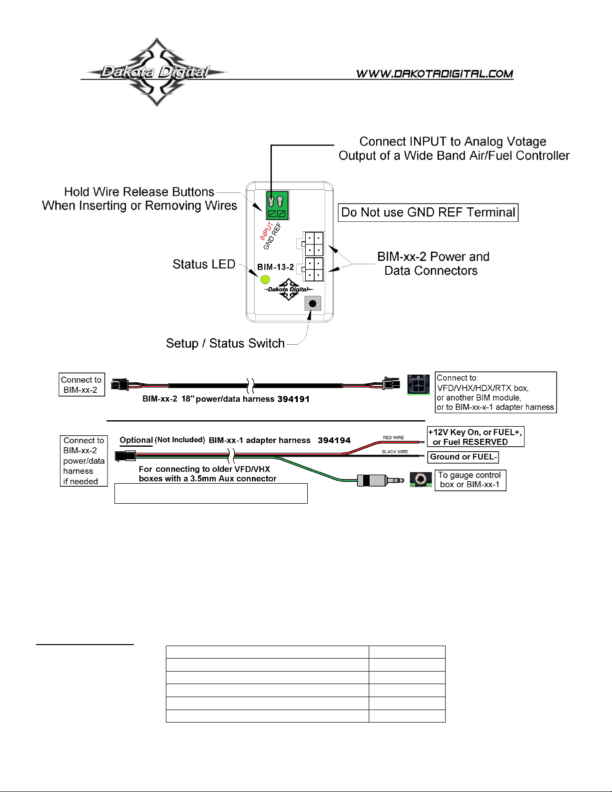
oA channel number will appear in front of the model –16 BIM-13-2
oIf NONE FOUND is displayed then check connections to the BIM-13-2.
oIf using multiple BIM units, follow Change ID step on top page 3.
•Tap either switch until 16 BIM-13-2 is selected.
oThe status LED on the BIM will flash RED-GREEN on the BIM selected.
•Press and hold either switch to enter setup. Release the switch when RELEASE is shown.
•The menu will show FORMAT, LABEL, WARN LO, WARN HI, CALIBRATE, BACK.
•Tap either switch to navigate the menu options,
•Hold either switch to enter that option. Release the switch when RELEASE is shown.
oFORMAT –How the temperature can be displayed, hold until RELEASE to enter.
▪Tap either button to scroll through, press and hold either button to select.
▪*DIGITAL –digital number readout “xxx A/F”.
▪BAR –Air/Fuel or Lambda scale will be shown as a horizontal bar scale.
•Numbers on bar will change to match A/F scale used.
▪BACK –Exit FORMAT menu and return to BIM menu.
oLABEL –Not used.
oWARN LO–Adjustable low A/F reference point.
▪Press and hold to enter. Release when RELEASE is shown.
▪Tap left button, or SW1 (I), to decrease value.
▪Tap right button, or SW2 (II), to increase value.
▪Press and hold either button to save. Release when RELEASE is shown.
oWARN HI –Adjustable high A/F reference point.
▪Press and hold to enter. Release when RELEASE is shown.
▪Tap left button, or SW1 (I), to decrease value.
▪Tap right button, or SW2 (II), to increase value.
▪Press and hold either button to save. Release when RELEASE is shown.
oCALIBRATE –Not used.
•When finished tap to BACK, then press and hold to return to the BIM selection menu.
•If additional BIM modules need to be setup, it can be done by picking the next BIM in the list
•If done, tap either switch to BACK, then hold until RELEASE is displayed.
•Tap to EXIT SETUP, then hold to return to normal operation.

[6] MAN #650505D
To set or change the ID number:
The ID will not normally need to be changed. A green-red-red flash on the BIM-13-2 status light indicates an ID
conflict with another connected BIM. The following procedure will allow the BIM-13-2 to automatically select a new,
unused ID.
•Hold the switch on the BIM-13-2, then turn the key on. The BIM status light will be flashing RED.
•Release the switch.
•When the status light begins flashing green, the ID change is done.
Quick tips:
While the BIM is operating normally, the status light will flash green.
Steady green indicates it is powered up but not receiving any bus activity.
Flashing yellow-red (steady red with a flashing green) indicates an open or shorted temperature sensor connection.
Green flash-red flash indicates the BIM is currently selected in the instrument setup menu.
Green-red-red flash indicates an ID conflict with another connected BIM.
Troubleshooting guide:
Problem
Possible cause
Solution
-A/F reading does not show on
instrument readout
-BIM will not light up
-Power/data harness is damaged.
-Module is damaged.
-Inspect harness for damage or loose wires
-Verify power/data harness in plugged in correctly
-Return for service. (see page 8)
-A/F reading does not show on
instrument readout
-BIM CH 16 ERROR
-BIM has a steady-lit green LED
-Interface cable is not connected
-Interface cable is loose
-Another BIM is set with the same
channel ID
-On VHX systems, the BIM display
for this channel is disabled
-Connect the supplied data cable to the BIM unit and the
instrument system control box
-Ensure both ends of the cable are seated securely.
-Test module works when connected to control box alone
-Change ID of one BIM module so each uses a unique ID
-Follow instructions in VHX manual to enable the BIM
display screen
-A/F reading does not show on
instrument readout
-BIM LED is flashing green-red-
red
-Another BIM is set with the same
channel ID
-Test module works when connected to control box alone
-Change ID of one of the modules so each module uses
a unique ID
-A/F ratio does not read correctly
-Loose connection on sensor wire
-Connector not seated on controller
sensor
-Wrong setting for 0V display
-Wrong setting for 5V display
-Voltage or wiring problem in the
vehicle wiring harness
Inspect and reinsert sensor wire
-Reattach the sensor plug; ensure connector is secured,
verify controller is working
-Reset the 0V display setting using the system BIM setup
menu. This is the WARN LO setting
-Reset the 5V display setting using the system BIM setup
menu. This is the WARN HI setting.
-Check wiring harness for loose or damaged wires to
controller

[7] MAN #650505D
NOTES:

[8] MAN #650505D
SERVICE AND REPAIR
DAKOTA DIGITAL offers complete service and repair of its product line. In addition, technical support is
available to help you work through any questions or problems you may be having installing one of our
products. Please read through the Troubleshooting Guide. There, you will find the solution to most problems.
For additional support, please visit www.dakotadigital.com. A “Product Support” link will be found at the
bottom of the home page.
Should you ever need to send the unit back for repairs, please call our technical support line,
(605) 332-6513, to request a Return Merchandise Authorization number.
•Package the product in a good quality box along with plenty of packing material.
•Ship the product by a common carrier with tracking abilities.
•Be sure to include the RMA number on the package.
•Include a complete description of the problem, with RMA number, your full name and address (street
address preferred), and a telephone number where you can be reached during the day.
•Any returns for warranty work must include a copy of the dated sales receipt from your place of
purchase.
•Send no money. We will contact you for payment.
Dakota Digital Limited Lifetime Warranty
DAKOTA DIGITAL warrants to the ORIGINAL PURCHASER of this product that should it, under normal use and
condition, be proven defective in material or workmanship for the lifetime of the original vehicle it was installed in, such
defect(s) will be repaired or replaced at Dakota Digital’s option.
This warranty does not cover nor extend to damage to the vehicle’s systems, and does not cover diagnosis, removal or
reinstallation of the product.
This Warranty does not apply to any product or part thereof which in the opinion of the Company has been damaged
through alteration, improper installation, mishandling, misuse, neglect, or accident.
Dakota Digital assumes no responsibility for loss of time, vehicle use, owner inconvenience nor related expenses.
Dakota Digital will cover the return standard freight once the product has been evaluated for warranty consideration,
however the incoming transportation is to be covered by the owner.
This Warranty is in lieu of all other expressed warranties or liabilities. Any implied warranties, including any implied
warranty of merchantability, shall be limited to the duration of this written warranty. No person or representative is
authorized to assume, for Dakota Digital, any liability other than expressed herein in connection with the sale of this
product.
WARNING: This product can expose you to chemicals including lead, which is known to the
State of California to cause cancer and birth defects or other reproductive harm. For more
information go to www.P65Warnings.ca.gov
Table of contents
Other Dakota Digital Recording Equipment manuals

Dakota Digital
Dakota Digital BIM-01-2-HLLY User manual

Dakota Digital
Dakota Digital BIM-01-2-HLLY User manual

Dakota Digital
Dakota Digital BIM-01-2-HAL User manual

Dakota Digital
Dakota Digital SGI-5 E User manual

Dakota Digital
Dakota Digital BIM-04-2 User manual

Dakota Digital
Dakota Digital BIM-14-1 User manual

Dakota Digital
Dakota Digital DSL-1 E User manual

Dakota Digital
Dakota Digital BIM-01-2-MEGA User manual