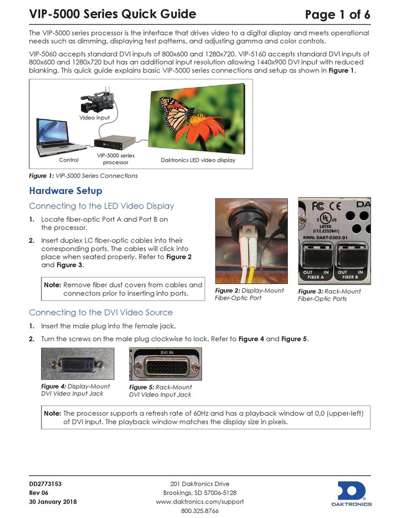
Daktronics VIP-4060 User manual

201 Daktronics Drive PO Box 5128 Brookings, SD 57006
tel 800-843-5843 fax 605-697-4700
www.daktronics.com
VIP-4060
Video Image Processor
Operator’s Manual
DD1804047 Rev 09—08 May 2015

DD1804047
Product 1578
Rev 09—08 May 2015
Copyright © 2015
All rights reserved. While every precaution has been taken in the preparation of this manual, the publisher assumes no
responsibility for errors or omissions. No part of this book covered by the copyrights hereon may be reproduced or copied in any
form or by any means—graphic, electronic, or mechanical, including photocopying, taping, or information storage, and retrieval
systems—without written permission of the publisher.
Daktronics is a registered trademark of Daktronics, Inc.
Firefox is a registered trademark of Mozilla Foundation.
Internet Explorer, Microsoft, Silverlight, and Windows are registered trademarks of Microsoft Corporation.
Java and JavaScript are registered trademarks of Oracle America, Inc.
McAfee is a registered trademark of McAfee, Inc.
Symantec is a registered trademark of Symantec Corporation.
ZoneAlarm is a registered trademark of Check Point Software Technologies, Inc.
All other trademarks are property of their respective companies.

Table of Contents i
Table of Contents
Section 1: Introduction.......................................................................................................................................... 1
1.1 Daktronics Contact Information ........................................................................................................................ 1
Section 2: First-Time System Setup & Launch ................................................................................................... 3
2.1 Physical Connections........................................................................................................................................... 3
DVX LED Display ......................................................................................................................................... 3
Video System ................................................................................................................................................. 3
Supported DVI/VGA Resolutions ...................................................................................................... 3
Connecting SDI or Daktronics V-Max™4 Signal............................................................................... 3
Connecting DVI Video.......................................................................................................................... 4
Temperature and CAN Light Sensors........................................................................................................ 4
Phoenix Connection...................................................................................................................................... 4
Network.......................................................................................................................................................... 4
Power .............................................................................................................................................................. 4
2.2 Computer-to-VIP-4060 Communication........................................................................................................... 4
Downloading DisplayFind Application .................................................................................................... 5
Launching DisplayFind Utility ................................................................................................................... 5
DisplayFind Utility ....................................................................................................................................... 5
Finding the VIP-4060 Network Internet Protocol (IP) Address ............................................................. 6
2.3 Computer System Requirements ....................................................................................................................... 6
2.4 Software Installation............................................................................................................................................ 7
Detecting & Installing Silverlight®Application........................................................................................ 7
Detection ................................................................................................................................................. 7
Installation .............................................................................................................................................. 7
Installing Java®Software.............................................................................................................................. 8
Enabling JavaScript®Language and Java®Software................................................................................ 8
Internet Explorer®Browser................................................................................................................... 8
Firefox®Browser .................................................................................................................................. 10
2.5 VIP-4060 System Login...................................................................................................................................... 10
2.6 ChoosingaCongurationPort ........................................................................................................................ 11
2.7 Displaying Initial Video .................................................................................................................................... 11
Display Control ........................................................................................................................................... 11
Display Adjustments .................................................................................................................................. 12
Display Backup............................................................................................................................................ 13
Section 3: User Interface Basics ........................................................................................................................ 15
3.1 Window Basics.................................................................................................................................................... 15
3.2 Communication Indicators ............................................................................................................................... 15
Communication Status............................................................................................................................... 15
Failed & Pending Communication........................................................................................................... 16
3.3 Application Menu .............................................................................................................................................. 16
Help/Manual Icon...................................................................................................................................... 16
About Icon.................................................................................................................................................... 16
Communication Settings Icon ................................................................................................................... 16
Timeouts................................................................................................................................................ 16
Conguration ....................................................................................................................................... 16
BackupDisplayCongurationIcon......................................................................................................... 17

ii Table of Contents
LoadDisplayCongurationBackupIcon............................................................................................... 17
RetrieveCongurationIcon ...................................................................................................................... 17
SendCongurationIcon ............................................................................................................................ 17
3.4 Using Primary & Backup VIP-4060 Systems.................................................................................................. 18
Section 4: VIP-4060 Conguration Tabs............................................................................................................ 19
4.1 Display Control Tab........................................................................................................................................... 19
Display Mode .............................................................................................................................................. 20
Test Pattern ........................................................................................................................................... 20
DVI......................................................................................................................................................... 21
SDI.......................................................................................................................................................... 21
VMax...................................................................................................................................................... 21
Custom Image ...................................................................................................................................... 21
Module Pattern..................................................................................................................................... 21
Dimming Mode ........................................................................................................................................... 23
Auto ....................................................................................................................................................... 24
Manual................................................................................................................................................... 24
GPS......................................................................................................................................................... 24
ERTD...................................................................................................................................................... 24
Color Adjustment........................................................................................................................................ 25
Source & Target........................................................................................................................................... 26
Source .................................................................................................................................................... 26
Input Video Status ...................................................................................................................................... 26
4.2 Tools Tab ............................................................................................................................................................. 27
Set Time/Date ............................................................................................................................................. 27
Run File Check............................................................................................................................................. 27
Reset Display ............................................................................................................................................... 28
Clear Memory.............................................................................................................................................. 28
System Status Information......................................................................................................................... 28
4.3 Additional Tabs .................................................................................................................................................. 29
Section 5: Exchange/Repair & Return Programs ............................................................................................. 31
5.1 Exchange Program ............................................................................................................................................. 31
5.2 Repair & Return Program ................................................................................................................................. 32
Shipping Address........................................................................................................................................ 32
5.3 Daktronics Warranty & Limitation of Liability ............................................................................................. 32
Glossary ............................................................................................................................................................. 33
Appendix A: Technical Specications................................................................................................................... 35
Appendix B: Supplementary Documents .............................................................................................................. 37
Appendix C: Daktronics Warranty & Limitation of Liability................................................................................. 39

Introduction 1
Section 1: Introduction
This manual is intended to help Daktronics customers operate the VIP-4060. Daktronics recommends
reviewing all of the information in this manual in order to understand the features that the VIP-4060 offers.
This manual assumes the user has a basic working knowledge of the Windows®operating system, including
using menus and folders. If a user is unfamiliar with this operating system, there are many resources
available to assist in understanding it. Terms that describe commonly used personal computer operations are
used frequently in this manual.
1.1 Daktronics Contact Information
Users can access the VIP-4060 Operator’s Manual via the blue question mark button in the top-left corner of
the screen. If further assistance is required, Daktronics Customer Service is available 24/7 via phone or
online connection.
Daktronics Customer Service can be reached via telephone by calling either number below:
• United States and Canada: 1-800-DAKTRON (1-800-325-8766)
• Outside the U.S. and Canada: +1-605-697-4000
Daktronics online customer support can be reached by entering the address below into a web browser:
• www.daktronics.com/support


First-Time System Setup & Launch 3
Section 2: First-Time System Setup & Launch
2.1 Physical Connections
DVX LED Display
ConnectingtheVIP-4060totheDVXLEDdisplayrequiresduplexLCber-optic
cables. To connect the VIP-4060 to the display, follow the steps below while
referring to Figure1:
1. Locate Port A and Port B on the back of the VIP-4060.
Note:Both ports can be used to connect primary data and back-up data to
the display.
2. InserttheduplexLCber-opticcablesintotheircorrespondingports.
The cables will click into place when seated properly. Match the supplied
cable label to the port label.
Note:Removeberdustcoversfromcablespriortoinsertingintoports.
Video System
There are four video feed options - DVI, 720p SDI, 1080p @30fps SDI, or Daktronics V-Max™signal - for
connecting a video feed to the VIP-4060 system. The type of video feed determines which will be used. In
stand-alone systems, the options are generally 720p SDI or DVI. Daktronics-supplied control systems use
V-Max™4 signal output to connect components.
Note:DVI resolutions up to SXGA are supported (i.e. 640x480, 800x600, 1024x720, 1280x720, 1280x960,
1280x1024, 1400x900).
Supported DVI/VGA Resolutions
Video Standard Resolution
(Pixels) Video Standard Resolution
(Pixels)
VGA 640x480 WXGA 1360x768
SVGA 800x600 SXGA 1280x960
XGA 1024x768 SXGA 1280x1024
WXGA 1280x720 WXGA+ 1440x900
Connecting SDI or Daktronics V-Max™4 Signal
To connect the video feed to the VIP-4060 system, follow the steps below:
1. Connect the BNC cable to the top SDI/V-Max™4 input. Refer to Figure2.
2. Rotate the connector a quarter turn clockwise to lock.
3. Ensure that a 75 ohm terminator is connected to the bottom BNC.
Note:The bottom BNC does not function as a loop out on the VIP-4060.
Figure 1: Fiber-Optic Ports
Figure 2: SDI/V-Max™4
Input

4 First-Time System Setup & Launch
Connecting DVI Video
To connect the DVI video to the VIP-4060 system, follow the steps below:
1. Insert a male plug into the female jack.
2. Turn the screws on the male plug clockwise to lock. Refer to Figure3.
Temperature and CAN Light Sensors
To enable temperature and light sensors, follow the steps below while referring
to Figure4:
1. Connect the Daktronics-supplied sensor cable to the Light/Temp port.
2. Rotate the connector clockwise a quarter turn to lock.
Phoenix Connection
Use the Phoenix connection to enable peripheral devices such as direct light
sensors. Refer to Figure5.
Network
To connect the VIP-4060 to the network, follow the steps below:
1. Connect an RJ45 network cable to the network port on the VIP-4060.
Refer to Figure6.
2. Connect the other end of the cable to the computer or network.
Power
To connect power to the VIP-4060, follow the steps below:
1. Connect the cord into the jack on the VIP-4060. Refer to Figure7.
2. Plug the cord into an outlet.
2.2 Computer-to-VIP-4060 Communication
Once the physical connections have been made, navigate to the network address
oftheVIP-4060torunthecongurationapplicationstoredwithinthedevice.The
IP address is located in the documentation that arrived with the equipment or on
the label on the back of the VIP-4060.
TechNote: New customers receive the VIP-4060 with a
factory-determined IP address in the equipment documentation. The
DisplayFind utility helps technicians in troubleshooting situations.
Figure 3: DVI Input
Figure 4: Sensor Cable
and Port
Figure 5: Phoenix Connection
Figure 6: Network Input
Figure 7: Power Port

First-Time System Setup & Launch 5
Downloading DisplayFind Application
Users can download the DisplayFind application from either the control software CD or from the Internet. To
downloadtheDisplayFindlefromtheInternet,followthestepsbelow:
1. Open a web browser (i.e. Internet Explorer®or Firefox® browser).
2. Navigate to dakles.daktronics.com.
3. Click venus1500>Utils>DisplayFind>DisplayFind.exe.
4. Select Run to download the DisplayFinder utility or Savetosavetheleto
the computer for later use.
Launching DisplayFind Utility
TheDisplayFindleautomaticallyopensifRun was selected in Step 4 above.
If Save was selected instead of Run,locatewheretheDisplayFindlewassavedduringdownloadand
double-click the icon to open the program. Refer to Figure8.
DisplayFind Utility
Each item listed at the top of the DisplayFind utility should have a green check mark as shown in
Figure9. If an item has a red Xnext to it as shown in Figure10, click it for additional information or to access
the download.
Figure 9: DisplayFind Utility Window
A red Xis shown next to TheCurrentUserIsNotAnAdministrativeUserOnThisComputer if the user
does not have administrative rights on the computer being used. Administrative rights are needed to install
the Silverlight®application. After installation, administrative rights are no longer necessary.
A red Xis shown next to WindowsFirewallisCurrentlyBlockingCommunication if the Windows®
rewallisnotdisabled.Windows®rewallshouldbetemporarilydisabledtoallowdiscoveryresponsesto
bereceivedfromanydisplays.Otherthirdpartyanti-virus/rewallapplications(i.e.McAfee®, Symantec®,
ZoneAlarm®software, etc.) should also be temporarily disabled.
Note:FirewallexceptionsshouldbeconguredtoallowinboundTCPandUDPtrafconPort3702if
temporary disabling is not desired.
A green check mark next to SilverlightVersion indicates that the Silverlight®application is installed on the
computer. A red Xindicates that the Silverlight®application is not installed or that the installed version is not
Silverlight®2.0 or newer.
Figure 8: DisplayFind Icon
Figure 10: DisplayFind Utility Errors

6 First-Time System Setup & Launch
Finding the VIP-4060 Network Internet Protocol (IP) Address
AfterinstallingtheDisplayFindprogram,followthestepsbelowtondthenetworkIPaddress:
1. Start the DisplayFind application.
2. Click FindDisplays. Refer
to Figure11.
3. Click the drop-down arrow next to the
AdapterName text box and choose the
Ethernet adapter to connect to
the controller.
4. Select the correct controller
name for the site from the list of
controllers found.
Note:If multiple VIP-4060 controllers
are found, use the Media Access
Control (MAC) address or Dynamic
HostCongurationProtocol(DHCP)
name from the label on the back of
the VIP-4060 to select the appropriate system. The address name begins with M4 or DAKT. Refer to
Figure12 and Figure13 for examples.
Figure 12: M4 Address Name
2.3 Computer System Requirements
For the best experience, the VIP-4060 requires the following:
• Silverlight®2.0 application (or newer)
• Java®software 1.6.0.14 (or newer)
• JavaScript®enabled in the browser
For the best browser experience, the VIP-4060 requires the following:
• Internet Explorer®6.0 browser (or newer)
• Firefox®3.5 browser (or newer)
Figure 11: Display Finder
Figure 13: DAKT Address Name

First-Time System Setup & Launch 7
2.4 Software Installation
Detecting & Installing Silverlight®Application
If the DisplayFind utility was not used to connect to the display, open a web browser window and follow the
steps in the following section to download and install the Silverlight®application.
Silverlight®application version 2.0 or newer is required to use the VIP-4060. The VIP-4060 will indicate if the
system needs to install the Silverlight®application or perform an update (internet access required).
Detection
To determine if the Silverlight®application is already installed, open
an internet browser window and enter the VIP-4060 system’s IP
address into the browser’s address bar (i.e. http://<IPaddress>).
If the Silverlight®application is installed, the VIP-4060 login window
will open; if no login window opens, the Silverlight®application
needs to be installed.
Installation
If the Silverlight®application is not installed on the host
machine, the user will see the InstallMicrosoft®Silverlight®
icon as shown in Figure14. To install the Silverlight®
application, follow the steps below:
1. Click the Install icon as shown in Figure14. This
will cause the FileDownload-SecurityWarning
window to open.
2. Click Run in the security warning window. Refer to
Figure15. The InstallSilverlight®dialog box opens
next. Refer to Figure16.
3. Click Installnow in the dialog box to begin installation. The InstallationStatus window tracks the
progress of the installation. Refer to Figure17.
4. Click Close in the Installationsuccessful window to complete the Silverlight®program installation.
Refer to Figure18.
Figure 16: Installation Dialog Box
Following a successful installation, the DaktronicsRemoteDisplayConguration window opens to reveal
control tabs which include: DisplayControl, Tools, PanelAdjustment, Conguration, and Advanced. Refer
to Section4.1.
Figure 14: Silverlight®Installation Icon
Figure 15: File Download Security Window
Figure 17: Status Window Figure 18: Competed Installation

8 First-Time System Setup & Launch
Installing Java®Software
Java®softwareversion1.6.0.14ornewerisrequiredtousetheVIP-4060congurationapplication.IfJava®
software is not installed on the computer, the prompt in Figure19 will open during login.
Note:It is only necessary to install Java®Runtime Environment software.
Figure 19: Missing Plugins Prompt
To install Java®software, follow the steps below:
1. Click InstallMissingPlugins... as shown in
Figure19 or navigate to http://java.com/en/. Refer
to Figure20.
2. Enter http://<DHCPname> in the address bar (i.e.
http://M41053) after installing Java® software, and
proceed to the login instructions.
Note:Daktronics recommends disabling the Java®
cache. Refer to Section6.2.
Enabling JavaScript®Language and Java®Software
JavaScript®language must be enabled to use the VIP-4060 user interface. If JavaScript®language is not
enabled, a prompt will open or the user may be asked to install the Silverlight®application when it has
already been installed. JavaScript®language may be enabled in either the Internet Explorer®browser or the
Firefox® browser.
Internet Explorer®Browser
To enable JavaScript®language in the Internet Explorer®browser, follow the steps below:
1. Open the Internet Explorer®browser and select Manageadd-ons from the Tools menu drop-down
list. Refer to Figure21.
Figure 21: Manage Add-Ons
Figure 20: Java®Software Installation Prompt

First-Time System Setup & Launch 9
2. Click the drop-down arrow for the Showlist and select Alladd-ons. Refer to Figure22.
Figure 22: View All Add-Ons
3. Navigate to OracleAmerica,Inc. in the results window using the scroll bar on the right.
4. Select the line for JavaPlug-in1.60_xx and click the Enable button in the lower-right corner of the
window. Refer to Figure23.
Figure 23: Enable Java®Plug-In
5. Click the Close button to exit the window.
6. Restart the internet browser.

10 First-Time System Setup & Launch
Firefox®Browser
To enable JavaScript®language in the Firefox®browser,
follow the steps below:
1. Open the Firefox®browser and navigate to Tools
>Options in the drop-down menu list.
2. Click the Content tab in the Options dialog box.
3. Check the EnableJava and the EnableJavaScript
boxes. Refer to Figure24.
4. Click OK.
2.5 VIP-4060 System Login
To log in to the VIP-4060, follow the steps below:
1. Locatethesystem’sDynamicHostConguration
Protocol (DHCP) name on the label on the back of
the VIP-4060. This label will begin with either M
or DAKT. Refer to Figure12 and Figure13 on
page 6 for examples.
Note:The Internet Protocol (IP) address may be
used in place of the DHCP name.
2. Open an internet browser window and enter
http://<DCHP> into the address bar
(i.e. http://M41053 or http://DAKT020345). This
opens the login dialog box shown in Figure25.
3. Type Dak in the Username text box. The VIP-4060
isfactory-conguredwithnopassword.RefertoFigure25.
Note:Thedisplayadministratorcanchoosetopassword-protectthedeviceafterinitialconguration.
Daktronics recommends adding a password.
4. Click LogIn.
If the above login procedure is not successful, perform the following steps:
1. Open the DisplayFind application. Refer to
LaunchingDisplayFindUtility on page 5.
2. Click FindDisplays. Refer to Figure26.
3. Locate and select the controller name.
Note:If multiple controllers are found, reference
the MAC address or DHCP name from the label
on the back of the VIP-4060 to select the
appropriate system.
Figure 24: Enable JavaScript®Language
Figure 25: Login Dialog box
Figure 26: Display Finder

First-Time System Setup & Launch 11
If the login was unsuccessful, an error message will
appear in the Log In box. Refer to Figure27. Try logging
in again or contact Daktronics for assistance.
Note:If Java®software was installed just prior to login, a
series of warning security alerts will open:
• For the Javahasdiscoveredapplication
componentsthatcouldindicateasecurity
concernalert, click Yes.
• For the series of alerts Theapplication’sdigital
signaturecannotbeveried, click Run.
2.6 Choosing a Conguration Port
Thedefaultcongurationportis4500.Ifthisisnot
available, choose a new port by following the steps below:
1. Click the CommunicationSettings icon in the left
column of the application menu. Refer to
Figure28. This opens the Settings dialog box.
2. Select the Conguration sub-tab.
3. Uncheck the UseDefaultCongurationport
check box. Refer to Figure29.
4. Enterthenewcongurationportnumberinthe
CongurationPort text box or use the arrows to
change the number.
Note:The new CongurationPort setting is saved to a
temporarysettingsle.Whenthecacheiscleared,the
temporary settings are deleted and will need to
berecongured.
2.7 Displaying Initial Video
To quickly output initial video to the display and test the
functionality of the system, follow the instructions below. For more detailed information, refer to Section4.2.
Display Control
To show video on the display, follow the steps below:
1. Navigate to the DisplayControl tab and select
the Displaymode/Testpatterns/Dimming
mode sub-tab. Refer to Figure30.
2. Select a video source (DVI, SDI, or V-Max) from
the Displaymode drop-down list.
Figure 27: Login Error Message
Communication Settings
Figure 28: Communication Settings Icon
Figure 29: Settings Conguration Tab
Figure 30: Display Control Sub-Tabs

12 First-Time System Setup & Launch
3. Select the Monitor drop-down list. Click Input or
Outputtoenableeasierconguration.Refer
to Figure31.
4. Click the Source&Target sub-tab and select
Source to choose the video signal. Refer
to Figure32.
5. ChooseallmodeforthedisplayfromtheFull,
Pillar, and Letterbox icons located above the
Source tab. Refer to Figure33.
Figure 32: Source & Target Sub-tab
Source & Target Sub-tab
6. Click the >>tab on the right-side of the window for additional display information.
Display Adjustments
Click the Displaymode/Testpatterns/Dimmingmode sub-tab to open the display adjustment controls.
• Dimming – To manually adjust dimming, choose Manual from
the Dimmingmode drop-down list and use the slider to select
the preferred value. Refer to Figure34. To automatically adjust
dimming, click Auto from the Dimmingmode drop-down list
and the display’s light sensor will adjust the values according to
environmental conditions. Dimming can also be determined by
the display’s location using GPS coordinates. Refer to Section4.1
and Section5 for additional dimming information.
• Gamma – To adjust gamma, navigate to the ColorAdjustments
withColorSpaceandGamma sub-tab. Use the slider to select the preferred gamma value. Refer
to Figure35.
Figure 35: Color Adjustments Sub-tab
Figure 31: Monitor Drop-Down List
Figure 33: Display Fill Mode
Figure 34: Dimming Adjustment

First-Time System Setup & Launch 13
Display Backup
Displaybackupclonesallcongurationlesandthecurrenttranslationtable.Itishighlyrecommendedthat
thesystemcongurationisclonedpriortomakinganychanges.EachmachinethataccessestheVIP-4060
shouldincludeasavedworkingcopyofthecontrollerles.
Note:The Backupdisplayconguration function will duplicate all settings and Media Access Control
(MAC)addressesandoverwritelow-levelconguration.
Tobackupthecongurationles,followthestepsbelow:
1. Click the Backupdisplayconguration icon to open the SaveAs
window. Refer to Figure36.
2. Choose the SaveAs storage location by using the LookIn
drop-down list or the folder presentation pane. Refer to Figure37.
Note:AlllescanbedisplayedbyselectingtheFilesofType
drop-down list.
3. Typethenameofthesavedleinthe
Filename text box.
Note:Placing the date of the backup
inthelenameisusefulincases
wherethecongurationhasbeen
changed but the previous settings
may be needed again.
4. Click Savewhennished.
Refer to Section3.3 for more information.
Backup display conguration
Figure 36: Backup Icon
Figure 37: Save As Window


User Interface Basics 15
Section 3: User Interface Basics
The VIP-4060 system’s application windows share common elements that are always visible to the user,
including a basic header bar, presentation area, right column, and left column. Refer to Figure 38.
3.1 Window Basics
• HeaderBar contains the application title DaktronicsRemoteDisplayConguration.
• PresentationArea displays elements, information, and data related to current user selections and
systemtriggers.Settingsthatcanbemodiedbytheuserareshowninthisarea.
• RightColumn indicates the VIP-4060 communication status.
• LeftColumn contains icons and tools. The basic Help/Manual, About, and Communicationsettings
icons are always available. Following login, other icons and tools become available to the user.
Header Bar Right Column
Help/Manual
About
Communication Settings
Left Column
Presentation Area
Figure 38: Remote Display Conguration Screen
3.2 Communication Indicators
This section details the tools and features
available in the right column. Refer to Figure39
and Figure40.
Communication Status
• PossibleorActive – A green light
indicates that communication is
possible between the application
and the VIP-4060. A blinking green
light indicates that communication is
actively taking place. Refer
to Figure39.
Tasks – Click the green communication
status indicator light to view the Tasks
window. The open Tasks window lists
the tasks currently pending or recently
completed. Each task is listed as failed,
completed, or pending. Refer to
Figure40. Note: Do not drag the Tasks window outside the presentation area.
Communication status
Pending communication
Failed communication
Figure 39: Right Column Communication Features
Figure 40: Communication Tasks Window

16 User Interface Basics
Failed & Pending Communication
• The Failedcommunication icon, a red dot with an X in the upper-right column, indicates how many
failed communications occurred during the current session. Refer to Figure39.
Note: When the session closes, the browser resets to 0.
• ThePendingcommunication icon, a yellow caution dot in the upper-right column, indicates how
many communications with the display are pending. Refer to Figure39.
3.3 Application Menu
This section details the tools and features available in the
left column. Refer to Figure41.
Help/Manual Icon
The Help or Manual icon, located at the top of the left
column, provides access to the online operator’s manual.
About Icon
The About icon provides version details and contact
information for Daktronics.
Communication Settings Icon
Selecting the Communicationsettings icon opens the
Settings window which provides quick access to the
Timeouts tab and the Conguration tab.
Timeouts
Adjust the CommunicationTimeout setting by increasing
or decreasing the length of time (in seconds) that is allowed
to pass before the VIP-4060 reports a connection problem.
Refer to Figure42.
Monitortimelimit controls how long the monitored
stream is presented.
Conguration
Statusrefresh adjusts how frequently the video processor
status is retrieved. Use the controls to set the rate (in
seconds) at which the system and display are refreshed
with new data. Refer to Figure43.
Tomodifythecongurationportsettings,unchecktheUse
DefaultCongurationport check box and enter the new
port number in the CongurationPort text box. Refer
to Section2.6.
Help/Manual
About
Log out
Communication settings
Backup display conguration
Load display conguration backup
Retrieve conguration
Send conguration
Figure 41: Left Column Application Menu Buttons
Figure 42: Timeouts Tab
Figure 43: Conguration Tab
Other manuals for VIP-4060
1
Table of contents
Other Daktronics Media Converter manuals
Popular Media Converter manuals by other brands

Stahl
Stahl 9786 Series Handbook

GRASS VALLEY
GRASS VALLEY 8921ADT datasheet

Transition Networks
Transition Networks CETTF10XX-200 user guide

Bose
Bose Wave music system owner's guide

TRENDnet
TRENDnet TU-P1284 Quick installation guide

Analytic Systems
Analytic Systems VTC1000 Series Installation & operation manual