Daktronics ED-14743 User manual

Fiber Optic
Communication Manual
Installation, Maintenance,
& Troubleshooting
ED-14743 Rev 1 11 October 2004
331 32nd Ave PO Box 5128 Brookings SD 57006
Tel 605-697-4034 or 877-605-1113 Fax 605-697-4444

ED-14743
Product 1321
Rev 1 – 11 October 2004
DAKTRONICS, INC.
Copyright ©2004
All rights reserved. While every precaution has been taken in the preparation of this manual,
the publisher assumes no responsibility for errors or omissions. No part of this book covered
by the copyrights hereon may be reproduced or copied in any form or by any means – graphic,
electronic, or mechanical, including photocopying, taping, or information storage and retrieval
systems – without written permission of the publisher.
Galaxy®is a registered trademark of Daktronics, Inc. All others are trademarks of their respective companies.

Table of Contents
i
Table of Contents
Introduction................................................................................................................................1
Network Concepts......................................................................................................................1
System/Cable Requirements........................................................................................... 1
Component Identification............................................................................................... 1
Installation..................................................................................................................................2
Signal Termination Between Displays.......................................................................................3
Primary - Mirror............................................................................................................. 3
Primary – Primary (RS422)............................................................................................ 4
Primary – Primary (Fiber) .............................................................................................. 5
Replacement of the Fiber Optic Board.......................................................................................6
Alternate Location Installation...................................................................................................7
Troubleshooting .........................................................................................................................8
Signal Converter............................................................................................................. 8
Loop-Back test with Fiber.............................................................................................. 9
Conducting the Venus 1500 Software Test .................................................................... 9
Replacement Parts List.............................................................................................................11
Appendix A: Reference Drawings..................................................................... A-1


Introduction
The typical system consists of a Windows based personal computer running Venus 1500
software and one or more displays. In addition, some means of signal connection must be
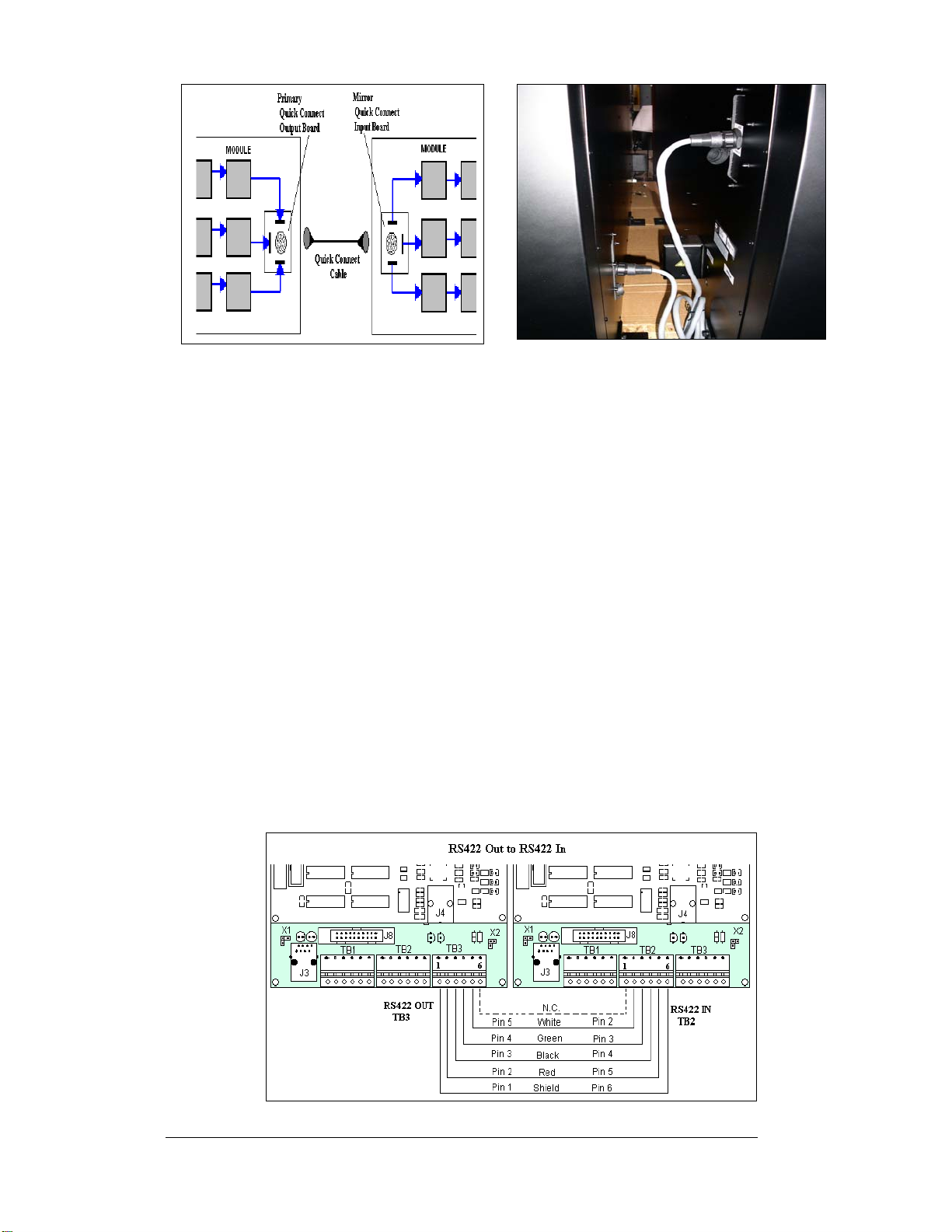
used to relay signal between the computer and the display. There are six network systems
available: RS232, RS422, Modem, Fiber Optic, Radio, and Ethernet. Up to 240 displays can
exist on one network.
The purpose of this manual is to explain those items that are unique to a fiber communication
system, including the installation and possible servicing requirements. In addition, if there is
more than one display the manual will discuss the possible ways of connecting signal between
displays.
Network Concepts
System/Cable Requirements
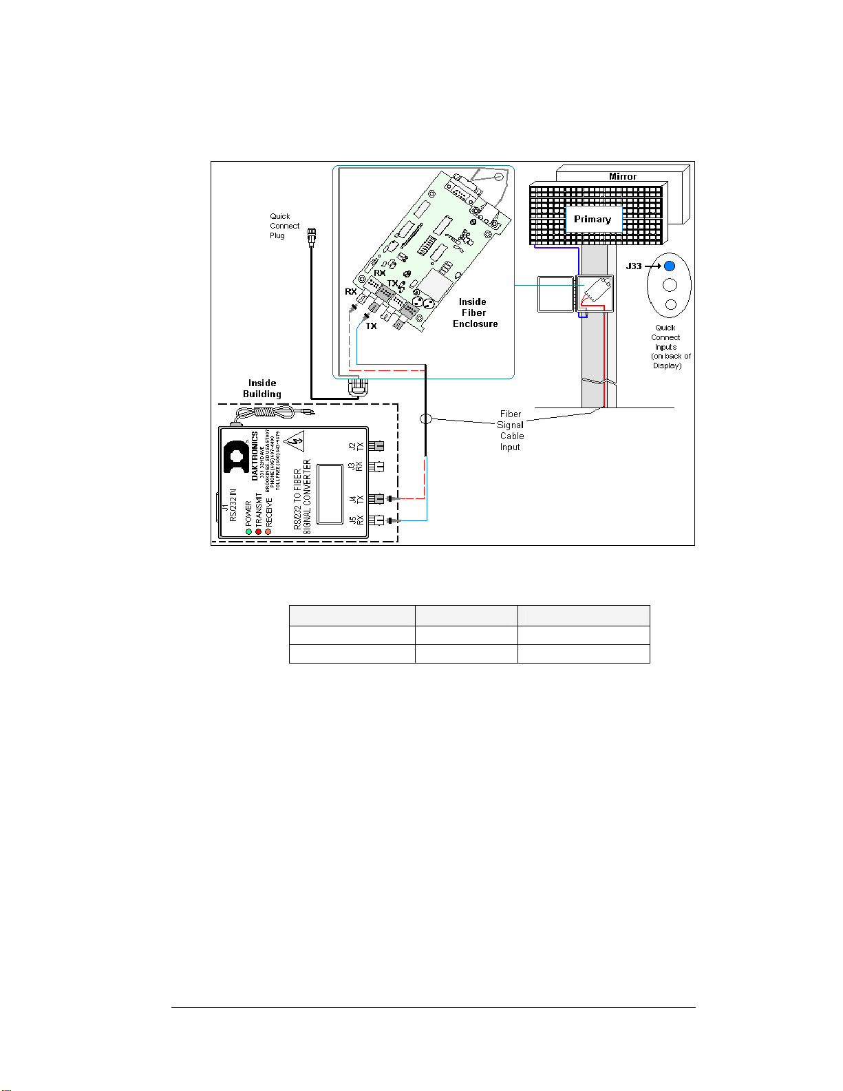
A fiber optic network is a standard communication method transmitting light (signal)
through a glass fiber. A signal converter is needed to convert the computer’s RS232
signal to fiber optic signal; a minimum of two fibers is required.
The cable is usually a 4-fiber cable (Daktronics part number W-1376). Two fibers
are used for display communications and the other two are saved for spares. The
cable may be either direct burial or routed in conduit, but it should not be subjected
to mechanical flexing. The maximum length of a fiber optic cable is 2,000 feet
(611.6 meters) from the signal converter to the fiber signal termination enclosure at
the display.
One advantage of using fiber over copper wire is that the signal and power lines can
be routed through the same conduit.
Component Identification
RS232: RS232 is a standard PC
communication type with a maximum cable
length of 25 feet (7.62 meters).
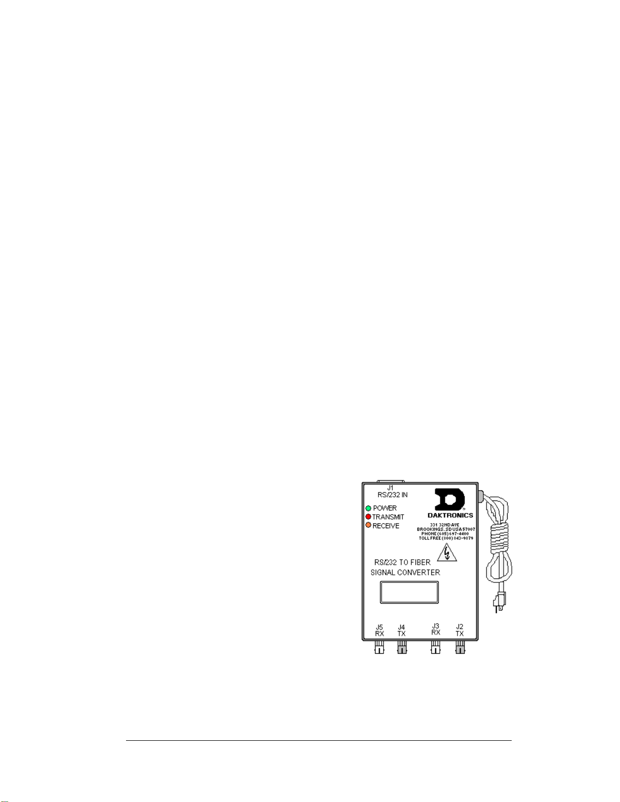
Figure 1: RS232 to Fiber Signal Converter
Signal Converter: The signal converter,
shown in Figure 1, is a Daktronics supplied
unit that converts the data from RS232 to
fiber optic signal. The signal converter is
connected to the control PC via a straight
through serial cable.
Serial Port: An actual serial port is required
for direct connections from the computer to
the signal converter.
Note: Certain USB adapters create an
“actual” serial port and others create
“virtual” ports. The Venus 1500
software will not recognize a virtual
port. Therefore, the use of a USB
adaptor is not supported by Daktronics.
Fiber Optic Communication Manual 1

Venus 1500: Daktronics designed, Windows®based software used to create and edit
messages on the display. Refer to the Venus 1500 Software manual, ED-13530, for
software operation.
Installation
Reference Drawings:
System Riser Diagram, Comm Box, Fiber, QC........................ Drawing A-211735
A fiber-controlled display requires the following connections:
1. The control computer connects to the signal converter (Daktronics part number 0A-
1127-0256) through a DB9 to DB25 serial cable (W-1249).
2. From the signal converter, fiber cable (Daktronics part number W-1376) is run to the
fiber optic board in the weather resistant enclosure at the display. (In certain cases,
the display may be ordered with the fiber optic board mounted in the display. In
those cases, the terminations will be the same.)
3. When connecting fiber cables, always connect transmit (TX) to receive (RX) and
receive (RX) to transmit (TX). Refer to Figure 2 and Drawing A-211735 for the
system layout.
4. In the case of fiber only, signal and display power can be run through the same
conduit.
Figure 2: Fiber Optic Display Controller
Note: The cable from the signal termination enclosure to the display can be routed though
conduit, through the display pole or should be secured to protect it from weather or
vandalism.
Complete the following steps to connect the signal termination enclosure:
1. Mount the signal termination enclosure within 25 feet of the display.
2. Route fiber optic cable to the enclosure. Two fibers are required.
3. Connect transmit (J4/J2) at the signal converter to receive (J5) in the enclosure and
receive (J5/J3) to transmit (J4). Refer to Figure 3 and the provided table for fiber
termination locations.
4. Connect the quick connect cable from the enclosure to the primary display. Connect
the cable to the red jack, J33, top, labeled RS 232/RADIO.
Fiber Optic Communication Manual
2

5. For displays with an internal fiber optic board only: Route the fiber cable into
the back of the display, being careful not to damage any interior components. Make
the connections to the fiber optic board as normal.
Figure 3: Signal Converter to Fiber Optic Enclosure
Signal Converter to Display Fiber Optic Board
Signal Converter Field Cabling Fiber Optic Board
J2 Transmit (TX1) (Color varies) J5 Receive (RX2)
J3 Receive (RX1) (Color varies) J4 Transmit (TX2)
Signal Termination Between Displays
Reference Drawings:
Controller II, Galaxy, 8-conn, J1087 .........................................Drawing B-204771
Primary - Mirror
Most displays are shipped as either a single Primary display or two displays in a 2V,
Primary – Mirror configuration.
The Primary – Mirror (2V) quick connect cable (W-1503) is used to terminate signal
between two displays. The six-foot cable goes from the Signal OUT (J34) on the
primary display to the Signal IN (J32) on the mirror display.
Fiber Optic Communication Manual 3

Figure 4: Quick Connect Boards
Figure 5: Display Interconnect
Primary – Primary (RS422)
If your location requires two displays that cannot be mounted back-to-back, two
primary displays will need to be installed. Those displays can be connected using an
RS422 signal cable or by fiber. In the case of RS422, the following connections will
need to be made:
1. Open the display, as explained in Section 4.4 of your display manual, and
locate the controller panel for these displays.
2. Route the cable through conduit from the back of the first primary display
to the back of the second primary display. Use one of the knockouts for
access, being careful not to damage any internal components
3. Use either a 4-pair signal cable or two 4-condutor, shielded cables to
connect both the signal and the temperature sensor information between
displays.
4. The signal cable will connect from TB3 out on the first primary display to
either:
• A surge board at TB1 in a second primary display
• (or) To TB2 on the controller in the second primary display.
• Note: In either case the connections are flipped. See the table and
Drawing B-204771 for connections on both displays.
• Signal connections between two controllers are shown in Figure 6.
Figure 6: Interconnection from Primary to Primary
Fiber Optic Communication Manual
4

5. See the instructions for the Optional Temperature Sensor in the appendix of
the display manual for connections that need to be made for the temperature
sensor termination.
Primary – Primary Interconnect Cable
Face A – RS422
OUT (TB3) Field
Cabling Face B – RS422
IN (TB2)
Pin 1 (GND) Shield Pin 6 (GND)
Pin 2 (D2OUT-N) Red Pin 5 (D1IN-N)
Pin 3 (D2OUT-P) Black Pin 4 (D1IN-P)
Pin 4 (D2IN-N) Green Pin 3 (D1OUT-N)
Pin 5 (D2IN-P) White Pin 2 (D1OUT-P)
Pin 6 (Shield) Pin 1 (Shield)
Primary – Primary (Fiber)
If your location requires two displays that cannot be mounted back-to-back, two
primary displays will need to be installed. Those displays can be connected using an
RS422 signal cable or by fiber. In the case of fiber, the following connections will
need to be made:
1. Locate the signal enclosures or open the display, as explained in Section 4.4
of your display manual, to locate the controller panel for these displays.
2. Route the cable through conduit between the enclosures or from the back of
the first primary display to the back of the second primary display. In the
case of internally mounted fiber optic boards, use one of the knockouts for
access, being careful not to damage any internal components
3. Use the fiber cable to connect from transmit and receive of the output jacks
(J2 and J3) to transmit and receive of the input jacks (J4 and J5) on the fiber
optic board. Always connect transmit to receive and receive to transmit as
shown in shown in Figure 7 and the table.
4. See the instructions for the Optional Temperature Sensor in the appendix of
the display manual for connections that need to be made for the temperature
Figure 7: Fiber Optic Interconnect
Fiber Optic Communication Manual 5

sensor termination.
Fiber Optic Board (Primary 1) to Fiber Optic Board (Primary 2)
Fiber Optic Board Field Cabling Fiber Optic Board
J3 Receive (RX2) (Color varies) J4 Transmit (TX1)
J2 Transmit (TX2) (Color varies) J5 Receive (RX1)
Replacement of the Fiber Optic Board
The following directions are to replace a fiber optic board in the signal termination enclosure
mounted at the display. (In certain cases, the display may have been ordered with the fiber
optic board mounted in the display. The following directions are also true for those
installations.)
1. To replace a fiber optic board, first disconnect the power and signal connections
(refer to Figure 8 for connector locations).
2. The fiber optic board is held in place with four
nuts. Carefully remove them using a 5/16” nut
driver.
Fiber Optic Communication Manual
6
3. Install the new fiber optic board, replace the nuts
and reconnect power and signal cables.
The fiber optic board has three LEDs.
1. The green power LED (DS1) should remain lit
while power is applied to the fiberboard.
2. The amber receive LED (DS2) will flash when
the display fiber optic board is accepting signal
from the signal converter.
3. The red transmit LED (DS3) will flash when the
fiber optic board is sending to the signal
converter.
In addition, the fiber optic board has several input and
output jacks:
1. J4 and J5 are the two fiber connectors, to which
the fiber signal converter connects. (They can also be used for connecting to another
fiber optic board in a previous primary display if necessary.)
Figure 8: Fiber Optic Board in Enclosure
2. J6 is for the AC power coming from the display.
3. J1, a DB9 connector, that will transfer the signal to the display through the quick
connect cable.
4. J2 and J3 are used only if connected to a second fiberboard in another Primary
display. J7 is not used in the enclosure application.

Alternate Location Installation
Reference Drawings:
Schem; Primary Signal, Internal, with QC ................................Drawing B-206146
Note: If the display was ordered with the fiber optic board internally installed, these
connections have already been completed.
If necessary, the fiber optic board can be moved from the signal termination enclosure and
located in the display. The fiber optic board will be mounted on the standoffs next to the
controller board or in the left end of the display. The following connections will need to be
made for the fiber optic board to operate in the display:
1. Route the fiber through conduit to the back of the display. Use one of the knockouts
for access, being careful not to damage any internal components.
2. Connect two fiber lines of the fiber cable (Daktronics part number W-1376) from the
signal converter to the fiber optic board. Always connect receive on the signal
converter to transmit (J5) on the fiberboard and transmit at the signal converter to
receive (J4) on the fiber optic board.
3. Signal connects from the J7 output on the fiber optic board to J3 on the controller.
Use a straight 8-conductor, RJ45 cable (Daktronics part number 0A-1229-0054) to
make the connection.
4. Using the pre-terminated power cable, provided in the display, connect power from
the transformer (10 VAC) into J6 on the fiberboard.
5. See Figure 9 and Drawing B-206146 for fiber connections in the display.
Figure 9: Relocating the Fiber Board in the Display
Fiber Optic Communication Manual 7

Troubleshooting
Signal Converter
The following table gives the typical state of the signal converter when the LEDs are
either on or off. Refer to Figure 10 for an illustration of the signal converters and the
locations of the various components.
LED
Indicators Typical States Troubleshooting
ON Signal Converter (SC) is receiving
Power
SC is not receiving power
Power OFF Internal 1 AMP fuse is bad Replace SC
SC is not connected to a serial port Connect to open computer COM
port
On Steady 1. Serial port or serial cable is bad
2. Computer COM port in sleep mode 1. Try another port or replace
serial cable
2. Communicate to display
OFF Steady Normal state, SC is not transmitting
data
TX
Brief Flicker SC is transmitting data
ON Steady
1. Field Cabling between SC and
display is bad
2. Connected to display output jack or
terminated incorrectly
3. Bad COM port on display controller
1. Eliminate cabling by
disconnecting wire/cable from
SC to display controller
2. Check connections and
terminations
3. Eliminate by disconnecting
wire/cable to display controller
OFF Steady Normal state, SC is not receiving data
RX
Brief Flicker SC is receiving data
TX/RX ON Steady (If serial cable is connected) Bad SC Replace SC
Fiber Signal Converter (0A-1127-0256)
The following tables give the jack pin-outs for a fiber signal
converter.
Figure 10: RS232/Fiber Signal
Converter
J1 - 25 Pin DB-F
PIN OPERATION
2 TX-P (out)
3 RX-P (in)
7 GND
JACK OPERATION
J2 TX1 (out)
J3 RX1 (in)
J4 TX2 (out)
J5 RX2 (in)
Fiber Optic Communication Manual
8

Loop-Back test with Fiber
Fiber Optic Communication Manual 9
1. Locate the fiber optic board in the signal termination
enclosure.
2. Label the fiber ends connected to the board and carefully
remove them as shown in Figure 11.
3. Connect the ends into the fiber splice (Daktronics part# P-
1197), as shown in Figure 12.
4. When the fibers are connected, perform the loop-back test
using the Venus 1500 software as described in
Conducting the Venus 1500 Software Test
Figure 11: Fiber Optic Board
Figure 12: Connecting TX and RX Fibers with Fiber Splice
Conducting the Venus 1500 Software Test
1. Open Venus 1500 Administrator.
2. Click on Network Configuration and open the direct network by clicking on the
[+] in front of Direct Network.

3. Right click on the network you want to Test.
4. Click on [Test].
5. If the Transmit LED on the signal converter flickers the signal is getting to the
signal converter. That means that the right Com port is being used, however if it
does not flicker there is either a software or hardware problem with the
computer.
6. If you get the same message in the “Received” box as in the “Sent” box, the
loop-back test was successful, implying that the cable is good to that point.
7. If “No Response” appears in the “Received” box the test failed due to one of the
following problems:
Fiber Optic Communication Manual
10

Fiber Optic Communication Manual 11
a. The correct computer COM port is not being used or USB port is not
configured as a “serial” port. (If the Transmit LED flickered this was not
the problem.)
b. Communication problem:
• The fiber or the ends on the fiber are bad.
c. There was a problem conducting the test:
• The serial cable to the signal converter is bad or not plugged in.
• The signal converter is not plugged in.
8. If the words “It appears as if this port has a modem attached”, the modem will
need to be moved or you need to use a different COM port.
After the test is complete:
1. Remove the fiber splice, and reconnect fiber to fiberboard.
2. Run the test again, without the splice, and the test should fail.
3. Use Venus 1500 Display Manager to get status to ensure communication now
works correctly.
Replacement Parts List
The following table contains some of the items that may need to be replaced over a period of
time. Many of the parts also have their part numbers on labels affixed to them.
To prevent theft, Daktronics recommends purchasing a lockable cabinet to store manuals and
replacement/spare parts.
Part Description Part Number
Signal Converter, Fiber 0A-1127-0256
Fiber Signal Termination Enclosure (Comm. Box) 0A-1229-0107
Signal Board, RS232 to Fiber, 12V 0P-1127-0024
6-pin M to cable end, 25 ft, Fiber W-1484
Serial Cable, DB9-F to DB25-M, 6 ft. W-1249
Four Fiber cable, 62.5/125 grade W-1376
RJ45, M-M 18” cable, 8-conductor 0A-1229-0054
Plug; 1 pin F, Fiber optic, Splicer P-1197
Interconnect Cable; 31-pin male to 31-pin male, 6’,
QC W-1503
Quick Connect Interface, Input, w/Ethernet 0P-1229-2004
31-pin, Quick Connect Input/Output Board 0P-1229-2005


Appendix A: Reference Drawings A-1
Appendix A: Reference Drawings
The following drawings are listed in numerical order by size (A, B, etc.). Those drawings are
listed according to size.
System Riser Diagram, Comm Box, Fiber, QC...............................Drawing A-211735
Controller II, Galaxy, 8-conn, J1087................................................Drawing B-204771
Schem; Primary Signal, Internal, with QC.......................................Drawing B-206146


Table of contents
Other Daktronics Media Converter manuals