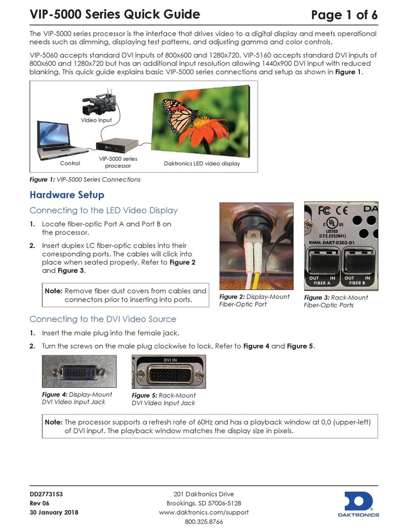
Daktronics VIP-4400 User manual

201 Daktronics Drive PO Box 5128 Brookings, SD 57006
tel 800-325-8766 fax 605-697-4700
www.daktronics.com
VIP-4400
Video Image Processor
Operator’s Manual
DD1709843 Rev 06—07 July 2015

DD1709843
Product 1278
Rev 06—07 July 2015
Copyright © 2015
All rights reserved. While every precaution has been taken in the preparation of this manual, the publisher assumes no
responsibility for errors or omissions. No part of this book covered by the copyrights hereon may be reproduced or copied in any
form or by any means—graphic, electronic, or mechanical, including photocopying, taping, or information storage, and retrieval
systems—without written permission of the publisher.
Daktronics, Venus, and V-Tour are registered trademarks of Daktronics, Inc. True Pixel and V-Max are trademarks of Daktronics, Inc.
Windows is a registered trademark of Microsoft Corporation.
All other trademarks are property of their respective companies.

Table of Contents i
Table of Contents
Section 1: Introduction.......................................................................................................................................... 1
1.1 Daktronics Contact Information ........................................................................................................................ 1
1.2 Product Information ............................................................................................................................................ 1
Section 2: System Logic Flow & Input Options .................................................................................................. 3
2.1 System Logic Flow ............................................................................................................................................... 3
2.2 Input & Output Options...................................................................................................................................... 3
2.3 EDID Supported Resolutions ............................................................................................................................. 4
2.4 SDI Supported Resolutions................................................................................................................................. 4
Section 3: Conguration Using Venus®7000 Software...................................................................................... 5
3.1 Using Venus®7000 Software............................................................................................................................... 5
3.2 Changing the Data Source .................................................................................................................................. 7
Section 4: Conguration Using Tera Term Software .......................................................................................... 9
4.1 Using Tera Term Software.................................................................................................................................. 9
4.2 Initial Setup ........................................................................................................................................................... 9
Section 5: Conguration Using V-Tour®Software ............................................................................................ 13
5.1 Using V-Tour®Software.................................................................................................................................... 13
5.2 Summary Window............................................................................................................................................. 13
Saving Display Conguration Settings.................................................................................................... 14
Section 6: Advanced Operation ......................................................................................................................... 15
6.1 Creating a Backup Conguration File............................................................................................................. 15
6.2 Creating a Backup Script File ........................................................................................................................... 16
6.3 Resetting to Factory Defaults............................................................................................................................ 19
Section 7: VIP-4510 Converter............................................................................................................................ 23
7.1 Basic Setup........................................................................................................................................................... 23
Section 8: Web Page Navigation ........................................................................................................................ 25
8.1 VIP-4400 Web Page ............................................................................................................................................ 25
8.2 Conguration Tab .............................................................................................................................................. 25
Channel......................................................................................................................................................... 25
General.......................................................................................................................................................... 26
Sign................................................................................................................................................................ 26
Set Default.................................................................................................................................................... 26
Download..................................................................................................................................................... 27

ii Table of Contents
8.3 Imaging Tab ........................................................................................................................................................ 27
Monitor......................................................................................................................................................... 27
8.4 Utilities Tab ......................................................................................................................................................... 28
Get Cong .................................................................................................................................................... 28
Get Status ..................................................................................................................................................... 28
Update Firmware........................................................................................................................................ 28
Reset.............................................................................................................................................................. 29
Section 9: Command Reference......................................................................................................................... 31
9.1 Channel-Specic Commands ........................................................................................................................... 31
9.2 Additional Conguration ................................................................................................................................. 33
9.3 Display Conguration....................................................................................................................................... 34
9.4 Data Distributor Conguration........................................................................................................................ 35
9.5 Effect/Transitions .............................................................................................................................................. 36
9.6 Miscellaneous Commands................................................................................................................................ 36
9.7 VIP-4510 Commands ......................................................................................................................................... 37
9.8 VIP-4510 Video Format Commands................................................................................................................ 39
Section 10: Exchange/Repair & Return Programs ............................................................................................. 41
10.1 Exchange Program ............................................................................................................................................. 41
10.2 Repair & Return Program ................................................................................................................................. 42
Shipping Address........................................................................................................................................ 42
10.3 Daktronics Warranty & Limitation of Liability ............................................................................................. 42
Glossary ............................................................................................................................................................. 43
Appendix A: Technical Specications................................................................................................................... 45
Appendix B: Daktronics Warranty & Limitation of Liability................................................................................. 47

Introduction 1
Section 1: Introduction
This manual is intended to help Daktronics customers operate the VIP-4400. Daktronics recommends
reviewing all of the information in this manual in order to understand the features that the VIP-4400 offers.
This manual assumes the user has a basic working knowledge of the Windows®operating system, including
using menus and folders. If a user is unfamiliar with this operating system, there are many resources
available to assist in understanding it. Terms that describe commonly used personal computer operations are
used frequently in this manual.
1.1 Daktronics Contact Information
Daktronics Customer Service is available 24/7 via phone or online connection.
Daktronics Customer Service can be reached via telephone by calling either number below:
• United States and Canada: 1-800-DAKTRON (1-800-325-8766)
• Outside the U.S. and Canada: +1-605-697-4000
Daktronics online customer support can be reached by entering the address below into a web browser:
• www.daktronics.com/support
1.2 Product Information
The VIP-4400 serves as an interface between a video source and a video display. The VIP-4400 has 10-bit
digital processing that allows for 4.4 trillion colors depending on display type. It accepts standard and
high-denition digital formats such as HD-SDI (up to 1080i), SD-SDI, VGA, SVGA, XGA, and SXGA in RGB
or DVI. The front and rear views of the VIP-4400 are illustrated in Figure1 and Figure2, respectively.
Figure 1: VIP-4400 – Front View
DVI/VGA INPUTS
HD/SDI DIAGNOSTICS
COMPOSITE/S-VIDEO/COMPONENT OUT DVI/VGA OUT
HD/SDI
OUT
VMAX4
OUT 2OUT 1
FIBER
RS232
IN OUT
LOOP
OUT
LOOP
OUT
LOOP
OUT
LOOP
OUT
1234
IN
OUT/IN
Not Field Serviceable AC 100-240 V~ 50/60Hz, 0.4 Amps
VIP-4400 Rev 07
NET
Figure 2: VIP-4400 – Rear View
The VIP-4400’s Active Input architecture provides aspect ratio versatility, allowing a wide range of video
sources to display on video boards with either traditional or non-traditional aspect ratios. Active Input
architecture also makes it possible to accept multiple live inputs and incorporate zoning, alpha blending,
keying, and seamless switching effects into a video presentation.
The VIP-4400 optimizes video signals for correct appearance on LED video displays. The processor uses
True Pixel™processing to reduce errors and noise inherent in video signals. Features of True Pixel™
processing include color space conversion, adjustable gamma correction, motion processing, and 3-D
noise reduction.


System Logic Flow & Input Options 3
Section 2: System Logic Flow & Input Options
2.1 System Logic Flow
The VIP-4400 accepts digital video sources as well as DMP content sent using Daktronics proprietary
V-Max™ 4 signal. This content typically consists of real time data, animations, AVIs, schedules,
and sequences.
After the VIP-4400 processes the incoming video signals, it sends a V-Max™4 signal to an A/B switch.
The primary system is routed to Port A and the backup system is routed to Port B. If the primary system
goes down, the A/B switch can send data from the backup system. Figure3 illustrates one possible way
to congure a control system. Please contact a Daktronics project manager for specic control
system information.
DMP-7000
primary
DMP-7000
backup
V-Max™4 signal
over ber-optic
cable or coax
VIP primary
VIP backup
A/B switch
Real-time data
Real-time data Video In
Video In
Out to monitor
Out to monitor
Out to display
V-Max™4 signal
over ber-optic
cable or coax
V-Max™4 signal
over ber-optic
cable or coax
V-Max™4 signal
over ber-optic
cable or coax
Figure 3: VIP-4400 System Logic Flow
V-Max™4 signal
over ber-optic
cable or coax
2.2 Input & Output Options
Each VIP-4400 is capable of simultaneously displaying up to four video sources in addition to one V-Max™4
signal. The video sources can be composed of a variety of video standards.
Up to four SD-SDI or HD-SDI sources may be displayed at
one time. These sources may come from a variety of digital
output devices including cameras, decks, switchers, and
DDRs. A BNC connection located in the lower center section
of the VIP-4400 accepts the feeds. Refer to Figure4.
Two DVI/VGA ports can accept either DVI or VGA sources.
Two sources may be connected at one time. These sources
come from a variety of devices such as desktop computers,
laptops, or content servers. Refer to Figure5.
The processor accepts V-Max™4 signals transmitted over
coaxial or ber-optic cable. Refer to Figure6. Only one input
can be active at a time. V-Max™4 signal may come from a
DMP-7000, another VIP-4400, or a VIP-4510.
Figure 4: SD-SDI & HD-SDI Loop Connectors
Figure 5: DVI/VGA Ports
Figure 6: V-Max™4 Inputs/Outputs

4 System Logic Flow & Input Options
2.3 EDID Supported Resolutions
VGA Resolution
(Height x Width) VGA Frame Rate (Hz) DVI Resolution
(Height x Width) DVI Frame Rate (Hz)
480 x 640 60 480 x 640 60
480 x 640 75 480 x 640 72
600 x 800 56 480 x 640 75
600 x 800 60 600 x 800 56
600 x 800 72 600 x 800 60
600 x 800 75 600 x 800 72
768 x 1024 60 600 x 800 75
768 x 1024 70 768 x 1024 60
768 x 1024 75 768 x 1024 70
1024 x 1280 60 768 x 1024 75
864 x 1152 75 1024 x 1280 60
720 x 1280 60 864 x 1152 75
960 x 1280 60 720 x 1280 60
960 x 1280 60
*900 x 1440 60
*Note: 900 x 1440 is the default DVI resolution.
2.4 SDI Supported Resolutions
SDI Resolution SDI Frame Rates (Hz)
480i 59.94
576i 50
720p 29.97, 30, 49.95, 50, 59.94, 60
1080i 49.95, 50, 59.94, 60
1080p 29.97, 30

Conguration Using Venus 7000 Software 5
Section 3: Conguration Using Venus®7000 Software
The V7 V-Link®Controller application in the Venus®7000 software program allows the operator to control
multiple VIP-4400s. Each VIP-4400 can output up to four video sources simultaneously. This section focuses
on setting up, adjusting, and operating multiple VIP-4400s and their inputs using the Venus®7000 software.
Refer to ED-14551 DMP-7000 Controller Operator’s Manual for more information.
3.1 Using Venus®7000 Software
To congure the VIP-4400 using Venus® 7000 software, follow the steps below:
1. Open the V7 V-Link®controller application in the Venus®7000 shell by clicking the V-Link icon or by
pressing V. The V7V-LinkController dialog box opens; refer to Figure7.
Figure 7: V7 V-Link Controller Dialog Box
2. Click the drop-downarrow next to Sign to select the sign to control if the correct sign is not
already displayed in the Sign drop down box. After selecting a sign, the SignType eld
automatically populates.
3. Click the drop-downarrow next to V-LinkIndex to select which VIP-4400 to control, or press Alt-X
and use the up and downarrows to select it. Up to three VIP-4400s may connect to the DMP-7000
per sign.
4. Click the drop-downarrow next to VLinkChannel to select the channel to control, or press Alt-C
and use the upanddownarrows to select it. Up to four channels can display per VIP-4400.
5. Click the drop-downarrow next to VideoFormat to select the preferred format for each channel, or
press Alt-M and use the up and downarrows to select the video format.
Note:Although listed, NTSC, PAL, and SECAM formats are not supported by
the VIP-4400.
6. Click the drop-downarrow next to TimeConst.Mode to select the
preferred mode.
Note:VTR works well for most applications.
7. Click the drop-downarrow next to Input to choose the desired input or press
Alt-I and use the up and downarrows to select it. Refer to Figure8. After
completing the setup procedure and conguring the settings for this input,
adjust the settings for each of the other inputs as well.
Figure 8: V-Max™4
Input Options

6 Conguration Using Venus 7000 Software
8. Click the drop-downarrow next to DataSource and select Video to play video
content on the display. Refer to Figure9.
9. Click Details or press Alt-D. The V7V-LinkController dialog box expands as
shown in Figure10.
10. Change the Top and Left quantities in the ViewableArea section to determine
what portion of the video feed will display. The default setting is the largest
area of good video feed available for display. This feed is centered and may be
adjusted as desired. Refer to Figure10.
Note:Save any changes to the ViewableArea and/or sourceWindowArea
settings. Click SavePositionSettings or press Alt-V to open the SavePositionSettings dialog box.
Type the name of the position settings (for example, “Position 1”). Click OK or press Enter to save the
settings under the entered name. Recall saved settings using the PositionSettings drop-down list.
Figure 10: V7 V-Link Controller Dialog Box
11. Adjust display Brightness, Contrast, Hue, and Saturation values with the slider bars in the Color
Adjustments section.
• To adjust brightness, move the Brightness slider bar or press Alt-N to move the cursor to the
Brightness setting and use the left and rightarrows to adjust.
• To adjust contrast, move the Contrast slider bar or press Alt-O to move the cursor to the
Contrast setting and use the left and rightarrows to adjust.
Figure 9: V-Max™4
Data Source Options

Conguration Using Venus 7000 Software 7
• To adjust hue, move the Hue slider bar or press Alt-U to move the cursor to the Hue setting
and use the left and rightarrows to adjust.
• To adjust saturation, move the Saturation slider bar or press Alt-T to move the cursor to the
Saturation setting and use the left and rightarrows to adjust.
12. Click SaveColorSettings or press Alt-Eto save the color settings. The SaveColorSettings dialog
box opens. Type the name of the color settings (for example, “Color 1”) and click OK or press Enter.
The settings are saved under the entered name and can be recalled using the ColorSettings
drop-down list.
13. Press Alt-K to move the cursor to the KeyColorLevels box and use Tab or Shift-Tab to move
between the color level boxes to set a key color if using overlay. Use the up and downarrow keys to
set the key color level.
Note:Daktronics does not recommend changing the key color after setting it. The VIP-4400 supports
256 intensity levels for each color (0-255). The default setting is Green 247 (Red 0, Green 247, Blue 0).
Create sequences with key color in mind and use only that color for sequences overlaid on the video.
14. Navigate to the Input menu and select the next video input (Channels 2-4). Repeat steps 3-13 to
adjust position or color settings for each input. Save settings after making adjustments.
3.2 Changing the Data Source
After the V7V-LinkController dialog box opens, as shown in Figure7, video immediately displays on the
default sign. Before an event, change the data source to the DMP-7000 controller. To change the data source,
follow the steps below:
1. Click the drop-downarrow next to DataSource and select Venus, or press Alt-A and use the up and
downarrows to select Venus.
Note:If the sign to control does not display in the Sign box, click in the Sign box and use the up and
downarrows to select the correct sign.
2. Click the drop-downarrow next to V-LinkIndex to select the desired VIP-4400, or press Alt-X and
use the up and downarrows to select the desired video processor.
3. Click the drop-downarrow next to VLinkChannel to select the desired output channel, or press
Alt-C and use the up and downarrows to select the output channel. Each VIP-4400 outputs
four channels.
4. Click the drop-downarrow next to Input to select the desired input, or press Alt-I and use the up
anddownarrows to select the input channel.
5. Click inside the PositionSettings text box and select the desired settings for this input or press Alt-P
and use the upanddownarrows to select the position settings.
6. Click inside the ColorSettings text box to select the desired color settings for this input setting or
press Alt-C and use the upanddownarrows to select the settings.
7. Click inside the DataSource text box and choose Video when ready to play video on the display, or
press Alt-A and use the upanddownarrows to select Video.
Note:If the monitor window is open, no video will play on the display because the video does not
send to the computer; the Venus®software data continues to play on the monitor.

8 Conguration Using Venus 7000 Software
8. Click the drop-downarrow next to Input to select a different input, or press Alt-I and use the upand
downarrows to select a new input.
9. Click inside the V-LinkIndex text box to select a different VIP-4400 from the drop-down menu, then
select the desired Input from the Input drop-down menu.
10. Click the drop-downarrow next to DataSource and click Venus to return to the box showing DMP
sequences, or press Alt-A to move the cursor to the DataSource text box and use the upanddown
arrows to select Venus.
11. Click the drop-downarrow next to DataSource and then click Overlayed to go to OverlayMode, or
press Alt-A to move the cursor to the DataSource text box and use the upanddownarrows to select
Overlayed. Refer to Figure9.
Note:OverlayMode allows for the display of any desired Venus®sequences. Once a sequence with
the key color displays, video plays inside the key color area.
12. Click Close to close the dialog box when nished.
Note:Spend time practicing the various functions such as switching between video sources
and inputs.

Conguration Using Tera Term Software 9
Section 4: Conguration Using Tera Term Software
Initial conguration and property edits of the VIP-4400 are typically accomplished using Venus®7000
software, however the Tera Term program provides another method for entering the same parameters. The
Tera Term software offers the GC (Get Conguration) command which produces a readout of current settings
used for troubleshooting.
4.1 Using Tera Term Software
To congure the VIP-4400 using Tera Term software, follow the steps below:
1. Link the VIP-4400 DB-9 connector port to an open COM port on the
Venus®7000 control computer with a serial cable. The DB-9 port on the
VIP-4400 console is immediately to the left of the V-Max™4 input port. Refer
to Figure11.
Note:Ensure the VIP-4400 is turned on and Venus®7000 sign service
is stopped.
2. Open the Tera Term program and go to Setup > SerialPort. The Serialportsetup window opens.
3. Enter the COM port on the DMP-7000 connected to the
VIP-4400 in the Port eld. Refer to Figure12.
4. Enter the following port settings:
• Baud rate: 115,200
• Data: 8bit
• Parity: none
• Stop: 1bit
• Flow control: none
4.2 Initial Setup
Conguration parameters needed to run the VIP-4400 for the rst time can be entered directly from the
Tera Term window. The conguration example shown in Figure13 on Page 11 lists commands for
conguring a 720x1280 display with one video input. Refer to Section6 for a list of all available commands
and their key combinations.
Parameter Example Description
SI 41
Video Input Selection
• 31 and 32 set VGA.
• 41–44 set SDI.
• 51 and 52 set DVI.
Figure 11: DB-9 Port
Figure 12: COM Properties Box

10 Conguration Using Tera Term Software
Parameter Example Description
VA 0 0 720 1280
Viewable Area
• The rst 0 indicates the vertical start location.
• The second 0 indicates the horizontal start location.
• 720 sets the pixel height the VIP-4400 controls.
• 1280 sets the pixel width the VIP-4400 controls.
WA 0 0 480 640
Window Area
• The rst 0 indicates the vertical start point of the window.
• The second 0 indicates the horizontal start point of the window.
• 480 sets the value for the window height.
• 640 sets the value for the window width.
VB 128
Video Brightness
• 128 sets the video brightness level.
• The default value is 128.
• The range is 0–255. Zero is full black and 255 is full white.
VC 64
Video Contrast
• 64 sets the video contrast level.
• The default value is 64.
• The range is 0–127.
VH 128
Video Hue
• 128 sets the video hue.
• The default value is 128.
• The range is 0–255.
VS 64
Video Saturation
• 64 sets the video saturation level.
• The default value is 64.
• The range is 0–127. Zero is full black and 127 is completely saturated.
SS I
Source Selection
• I sets the data type to Video.
• V sets the DMP-7000 as the data source.
• O selects Overlay which displays DMP-7000 data over video signal.
CS 744 1280
Display Size
• 744 sets the height in pixels.
• 1280 sets the width in pixels.
SP 26 1 744 1280 Absolute Sign Position
DD 63
Display Dimming
• The default value is 127.
• The range is 0–127.
DG 22
Display Gamma
• 22 sets the data distributor gamma value.
• The range is 10–41 which is 1.0 to 4.1.

Conguration Using Tera Term Software 11
Check that all other parameters are set as shown in Figure12. Refer to Figure13 for an example of
Tera Term conguration.
Note:Enter CSF to save the settings. To avoid losing these settings, do not power the VIP-4400 off and on.
Figure 13: Sample Conguration


Conguration Using V-Tour® Software 13
Section 5: Conguration Using V-Tour®Software
Initial conguration and property edits of the VIP-4400 are typically accomplished using Venus®7000
software, however the V-Tour®program provides another method for entering the same parameters.
5.1 Using V-Tour®Software
To congure the VIP-4400 using V-Tour® software, follow the steps below while referring to Figure14
and Figure15.
1. Enter the name of the VIP in the Name text box. When the conguration uses more than one
VIP-4400, use descriptive names to avoid confusion (e.g. VIP, Left VIP, Right VIP).
2. Choose Network or Serial in the Communications box.
• If Network is chosen, enter the corresponding IP address.
• If Serial is chosen, select the Port from the drop-down list.
Note:The port must be different from the port selected in the Display window.
Figure 14: New Network VIP-4400 Figure 15: New Serial VIP-4400
3. Choose VIP4500/VLink4500 from the V-LinkType drop down list. Refer to Figure16.
Figure 16: V-Link Type Selection
4. Click Next. The Summary window opens.
5.2 Summary Window
The CongurationWizard Summary window provides an overview of information entered in the Display
and V-Link windows. Refer to Figure17on the next page.
Note:If the options listed in the Summary window are incorrect, click Previous to adjust.

14 Conguration Using V-Tour® Software
Figure 17: Conguration Wizard Summary Window
If the information in the Summary window is correct, follow the steps below:
1. Click Finish. The SendConguration dialog
box opens. Refer to Figure18.
2. Click Yes.
3. Select ImportSystemConguration from the
File menu.
4. Select the appropriate *.vcd le from the Open window.
5. Click Open.
Saving Display Conguration Settings
1. Select ExportSystemConguration from the
File menu. Refer to Figure19.
2. Name the display conguration in the Save
window and verify that the default le
extension is *.vcd.
3. Click Save.
Figure 18: Send Conguration Conrmation Box
Figure 19: Export System Conguration Menu

Advanced Operation 15
Section 6: Advanced Operation
This section describes advanced VIP-4400 operations. It is recommended that users perform these
operations only under the supervision of Daktronics Technical Support.
6.1 Creating a Backup Conguration File
A .VLC le functions as a backup conguration le external to the VIP-4400. Create .VLC les after
completing the initial setup or after changing the conguration. To create a backup conguration le, follow
the steps below:
1. Open the Venus®7000Shell.
2. Click the VLink button in the bottom-right corner. Refer to Figure20.
3. Select the sign connected to the VIP-4400 from the Sign drop-down menu. Refer to Figure21.
Figure 20: Venus®7000 Shell
4. Conrm the VLinkChannel eld is set to 1, and click the Details button. Refer to Figure22.
Figure 22: Verifying VLink Channel
Figure 21: Selecting Sign

16 Advanced Operation
5. Click the SaveCongurationSettings button in the bottom-left corner. Refer to Figure23.
Figure 23: Save Conguration Settings
6. Type the name of the .VLC le in the File
name text box and click Save.
Note:Choose a descriptive name for the .VLC
le that describes its corresponding
VIP-4400 and channel. It is also recommended
to include the date. For example, a .VLC le
for Channel 1 on a VIP that controls the left
half of the display might be named
Left_CH1(5-19-15).VLC. Refer to Figure24.
7. Repeat Steps 4–6 for each channel of
the VIP-4400.
6.2 Creating a Backup Script File
Follow the instructions below to create a backup script
for the VIP-4400. For additional information refer to
DD1834905 DMP-7000 Installation and Setup Manual.
1. Follow the instructions in Section6.1 to create
the necessary .VLC les before proceeding.
2. On the V7Dsply-Scripting window,
right-click on an unused cell and select Edit
Cell. Refer to Figure25.
Figure 24: Saving .VLC File
Figure 25: Editing Cell
Table of contents
Other Daktronics Media Converter manuals
Popular Media Converter manuals by other brands

DirekTronik
DirekTronik ZeeVee ZyPerMX4 user manual

Baumer
Baumer Hubner Berlin HMG 11 Mounting and operating instructions

PAC
PAC SOEM-4 Wiring instructions

Moxa Technologies
Moxa Technologies VPort 451 Quick installation guide

Speaka Professional
Speaka Professional 43 18 01 operating instructions

Lika
Lika ROTAPULS C101 Series manual