Elko eLAN-RF-003 User manual
1/25
Converter Ethernet to RF signal
eLAN-RF-003 Introduction:
Installation Manual
02-040/2012
Instruction Manual for the
eLAN-RF-003

2/25
Converter Ethernet to RF signal
eLAN-RF-003 Introduction:
Installation Manual
02-040/2012
Contents
1.Introduction:................................................................................................................................3
2.Main characteristics:....................................................................................................................3
3.Technical parameters: .................................................................................................................4
4.Hardware installation: .................................................................................................................5
4.1Front panel: ...........................................................................................................................5
4.2Rear panel: ............................................................................................................................5
4.3System requirements:...........................................................................................................6
4.4Requirements for installation environment:........................................................................6
4.5Examples of use: ...................................................................................................................6
5.Configuration of computer: ........................................................................................................8
6.Configuring the iMM Client:......................................................................................................11
7.Configuration of the eLAN-RF-003:...........................................................................................12
8.Configuring the eLAN-RF-003 using the SW eLAN-RF-003 Configurator:...............................12
8.1Administrator login:............................................................................................................13
8.2LAN parameters: .................................................................................................................13
8.3About the device:................................................................................................................13
8.4Buttons: ...............................................................................................................................13
8.5Device settings:...................................................................................................................14
8.5.1Basic settings. ..............................................................................................................14
8.5.2RF Repeater..................................................................................................................14
8.5.3RF Router .....................................................................................................................16
8.5.4List of addresses:..........................................................................................................18
8.5.5User panel: ...................................................................................................................19
9.Configuring the eLAN-RF-003:..................................................................................................20
9.1Settings tab: ........................................................................................................................21
9.2Tab Firmware: ......................................................................................................................22
9.3Tab Builder: .........................................................................................................................23
9.4Tab Panel: ............................................................................................................................24
9.5Tab log out: .........................................................................................................................24
10.Troubleshooting: ....................................................................................................................25

3/25
Converter Ethernet to RF signal
eLAN-RF-003 Introduction:
Installation Manual
02-040/2012
1. Introduction:
Congratulations on purchasing the eLAN-RF-003 control unit, an element of the RF Control wireless system.
Before you begin
The instruction manual provides information on installing and operating the device. The instruction manual is
always a part of the supply. Only perform installation after becoming thoroughly familiar with this User Guide
and device functions.Problem-free function of the device also depends on the way it was shipped, stored and
handled. If you notice any signs of damage, deformation, malfunction or a missing part, do not install this product
and return it to the point of sale. At the end of its service life, the product and its parts must be treated as electronic
waste. Before starting the installation, make sure that all wires and connected parts are not under voltage. When
assembling and performing maintenance, you must uphold safety regulations, standards, directives and special
provisions for working with electrical equipment.
2. Main characteristics:
The eLAN-RF-003 converter converts commands from the LAN TCP/IP network to an RF signal for
controlling RF actuators.
It enables bidirectional communication between the RF INELS and Ethernet systems.
It can be used to extend the range of the RF signal via UTP cable (Ethernet network) or WiFi (between
individual floors in the house).
Option of control and reading values from RF actuators (temperature, ON/OFF status) - in the iMM
environment.
Configuration and management of ELAN-RF-003 is performed via:
1) iMM server
2) its own web server
3) configuration SW eLAN-RF-003 Configurator
For access to eLAN-RF-003 from the Internet, you must connect the eLAN-RF-003 to a Public IP address.
The device is compliant with standards 802.3/802.3u (Fast Ethernet)
The device is compliant with standards ISO 802.3/ IEEE 802.3u ( 10BASE-T)
Automatic cable crossing detection of Ethernet cable - MDIX
10/100BaseT Ethernet, auto-detection
Option of powering by PoE – maximum voltage 27V / 200mA max. consumption.
Support for administration and configuration via web interface.
Supports firmware updates via a web interface.
It has its own web server
Aluminum design box in desktop style.

4/25
Converter Ethernet to RF signal
eLAN-RF-003 Technical parameters:
Installation Manual
02-040/2012
3. Technical parameters:
Interface RF Control
Communications protocol: Oasis & RF Touch Compatible
Transmitting frequency: 868 MHz
Signal transmission method bidirectionally addressed message
Output for antenna: SMA Connector
Indication of RF communication: 1 x red RF Status LED
Antenna: 1 dB (part of supply)
Range in open areas: up to 100m
Ethernet Communication
Operating status indication ETH: green LED
Communication indication ETH: yellow LED
Communications interface: 10/100 Mbps (RJ45)
Preset IP address: 192.168.1.1
Supply voltage / jm. Current: 10-27 V DC / 200 mA (safe low voltage)
Power supply PoE Max. 27V / 200mA max. consumption
Connection: connector Jack Ø 2.1 mm
Supply voltage indication: green LED
Other
Other powering options: connector USB-B
USB activity indication: yellow USB Status LED
Button RESET: restart product / reset product to factory settings
Power source: 230 VAC / 12 V DC part of supply
Working temperature: -20 .. +55 °C
Storage temperature: -25 .. +70 °C
Protection class: IP 20
Pollution degree: 2
Working position: any
Installation: free
Design: design box
Dimensions: 90 x 52 x 65 mm
Weight: 136 g
Factory settings:
Login: admin, user
Password: elkoep
IP address: 192.168.1.1

5/25
Converter Ethernet to RF signal
eLAN-RF-003 Hardware installation:
Installation Manual
02-040/2012
4. Hardware installation:
4.1 Front panel:
Power connector DC 12V – Input for connecting supplied power adapter.
Plug USB B – Used for servicing, (or can be used to power the product).
Green POWER LED power supply indicator.
Yellow USB Status LED – displays activity at the USB port.
Button RESET – used to restart or restore the product to factory settings*.
Connector Ethernet RJ 45 – used to connect mainly to the local network (LAN) or PC.
Yellow LED on Ethernet connector - indicates operating status.
Green LED diode on Ethernet connector - indicates communication.
*By shortly pressing (around 1s) the RESET button in the status where the product is connected to the supply
voltage, the product will restart. This restart neither changes nor deletes settings.
RESET to factory settings occurs after pressing and holding the RESET for min. 10s. This restart returns the product to
its factory settings, i.e. the IP adress is set to 192.168.1.1, the user name and password are set at: admin /
elkoep, user / elkoep, all learning and assigned IR codes and
the created web server control panel are erased.
4.2 Rear panel:
Red RF STATUS LED – Displays RF communication – during transmission the RF signal LED diode flashes.
SMA antenna connector – pro connecting the RF antenna.
Power connector
10-27V/200mA
Yellow USB status LED
LED indicator of Ethernet
communication
Ethernet connector (RJ 45)
RESET button
Green POWER LED power supply indicator
USB B connector
Red LED RF STATUS SMA antenna connector

6/25
Converter Ethernet to RF signal
eLAN-RF-003 Hardware installation:
Installation Manual
02-040/2012
4.3 System requirements:
Functioning iMM Client or PC with functioning Ethernet adapter.
For PCs, installed web browser (such as Mozilla Firefox,Opera, etc.).
You must have installed .NET Framework 3.5 and higher.
Connecting Ethernet cable with RJ45 connectors.
4.4 Requirements for installation environment:
The product cannot be placed where it is exposed to moisture or excessive heat.
Place the eLAN-RF-003 at a location where it can be connected to the Ethernet network, power source and
its RF antenna will be in sufficient distance from the controlled device.
For fault-free communication, adhere to the principles of installing the RF device, see RF catalog.
4.5 Examples of use:
Connect the power supply using the supplied adapter.
Connect the eLAN-RF-003 device to the Ethernet by a cable to the computer, iMM Client, eLAN-RF-003 or
Ethernet hub.(The cable must have an RJ45 connector, the device has an automatic cable crossover
detection function - so cable crossover does not present a problem).
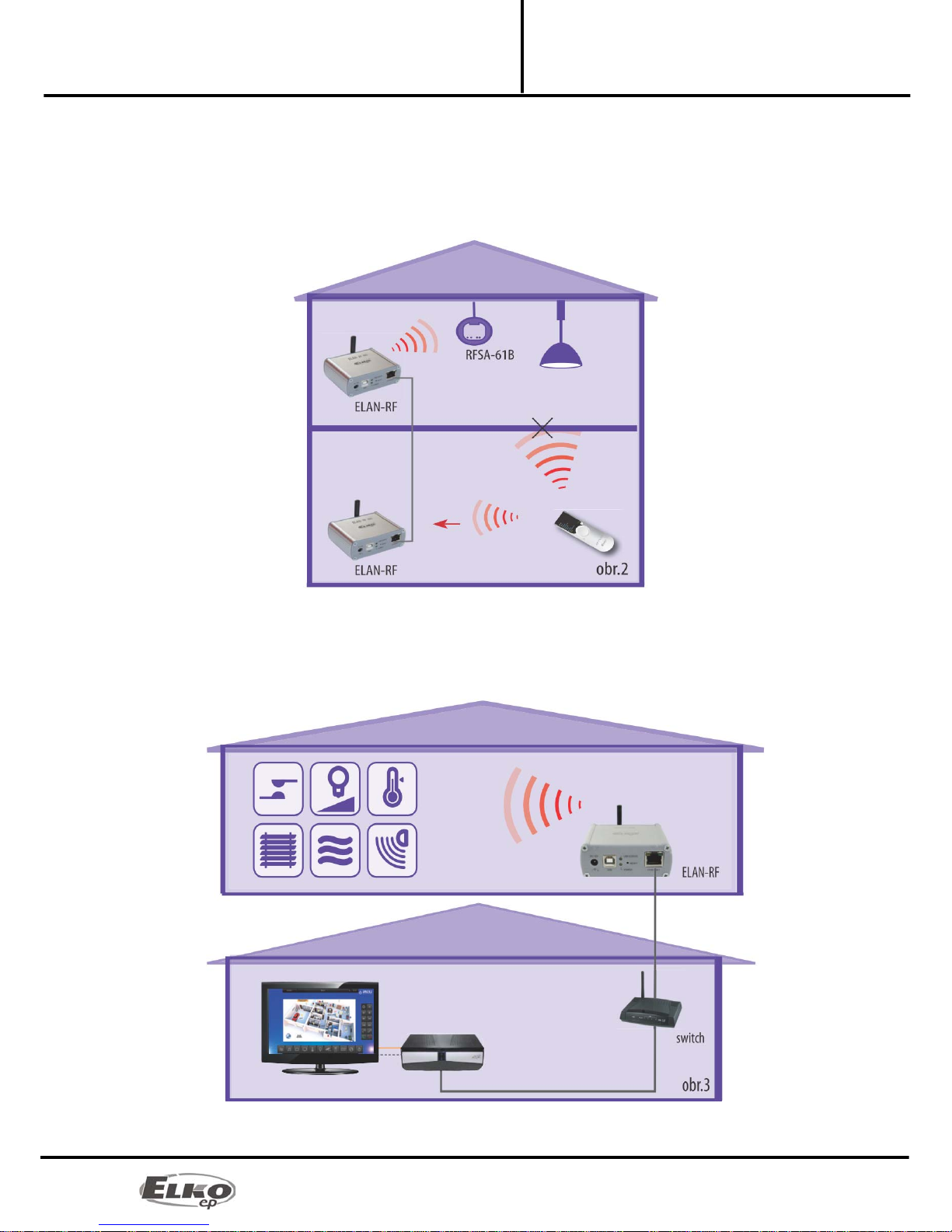
Example 1:
The example of use of two eLAN-RF-003 devices in connection with the WiFi network is advantageous when this
network is already in use, and is only augmented with the eLAN-RF-003 device. The eLAN-RF-003 device can
function if the WiFi routers are connected to a bridge and both eLAN-RF-003 devices can "see" each other. For this
case, it is necessary to set the eLAN-RF-003 to the routing function.
7/25
Converter Ethernet to RF signal
eLAN-RF-003 Hardware installation:
Installation Manual
02-040/2012
Example 2:
Basic use where the RF controller (RF Touch, RF Pilot, RFRF AP/USB, RF Key) cannot control the RF actuators, due to
great distance, and when it is not possible to use the RFRP-20 repeater. By simply connecting to the network or by
extending an Ethernet cable, you can extend the maximum range (distance) of RF controllers.
For this case, it is necessary to set the eLAN-RF-003 to the routing function.
Example 3:
The next example illustrates the case where you already own an iMM Client server and you want to control all the
RF actuators and maintain an overview on statuses of all RF actuators found within the range of the eLAN-RF-003.
8/25
Converter Ethernet to RF signal
eLAN-RF-003 Configuration of computer:
Installation Manual
02-040/2012
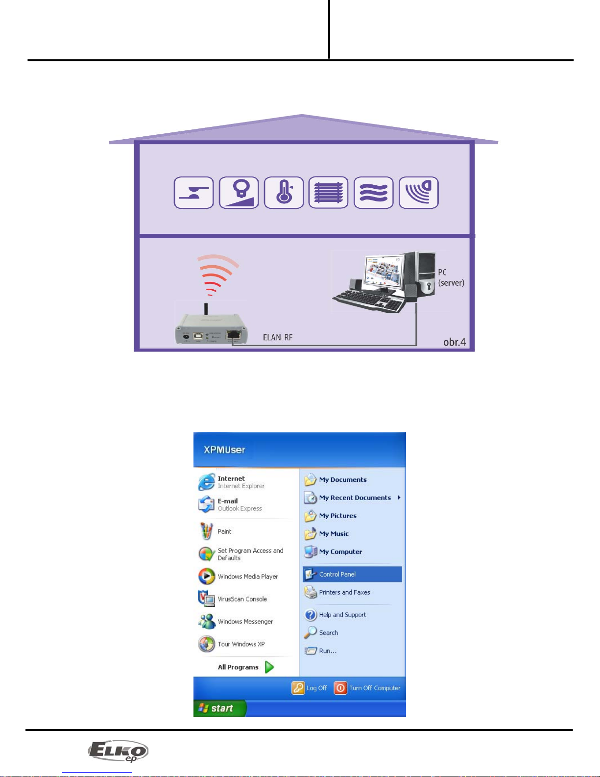
Example 4:
This example is similar to the previous one, except the device works via the PC. Thanks to the web server, it is easy to
control the RF actuators.
5. Configuration of computer:
For logging in to the web server or changing the IP address (192.168.1.1).
Example of configuration in the Windows system, proceed according to the following instructions:
1. In the computer Start menu, open the Control panel and select Network connections.
9/25
Converter Ethernet to RF signal
eLAN-RF-003 Configuration of computer:
Installation Manual
02-040/2012
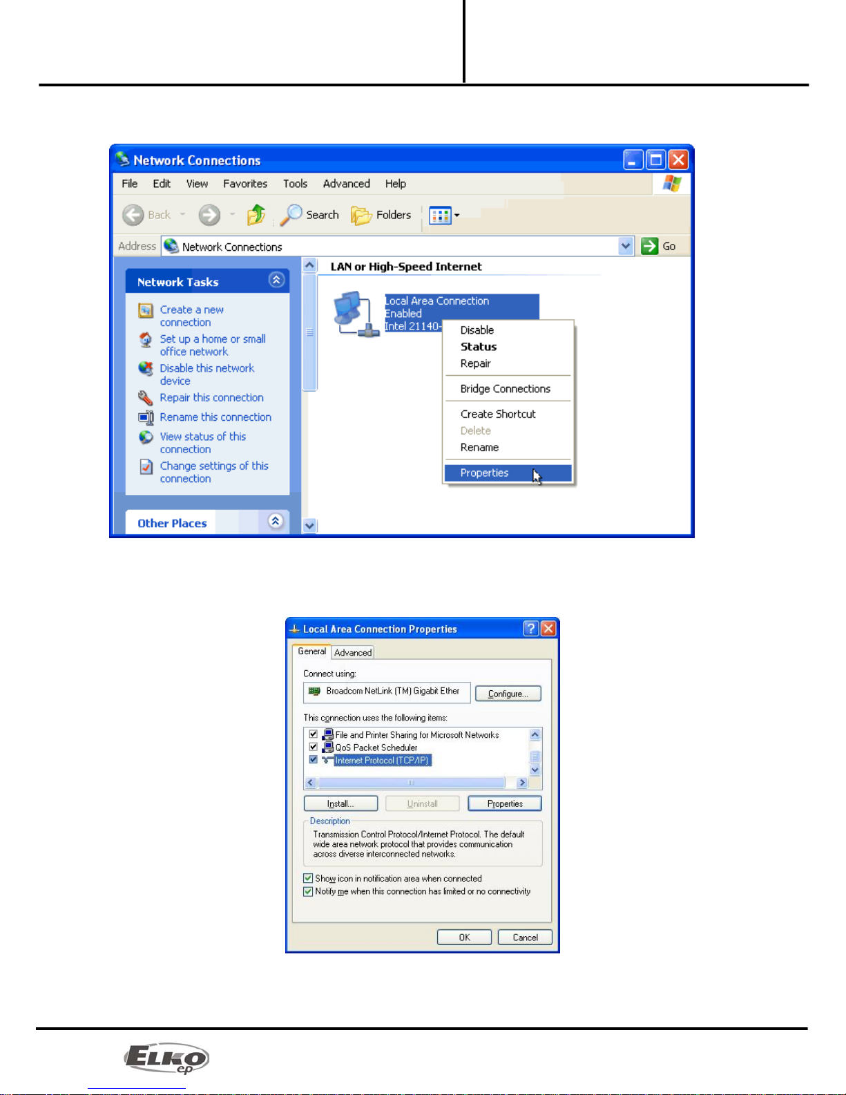
2. In the window Network connections right-click on LAN (connecting to local area network), then right-
click on Properties.
3. After opening the window: Connection to local network in the main dialog window, select "Protocol
Internet network (TCP/IP)". After choosing this type of protocol by clicking on Properties, another
configuration window opens.
10/25
Converter Ethernet to RF signal
eLAN-RF-003 Configuration of computer:
Installation Manual
02-040/2012
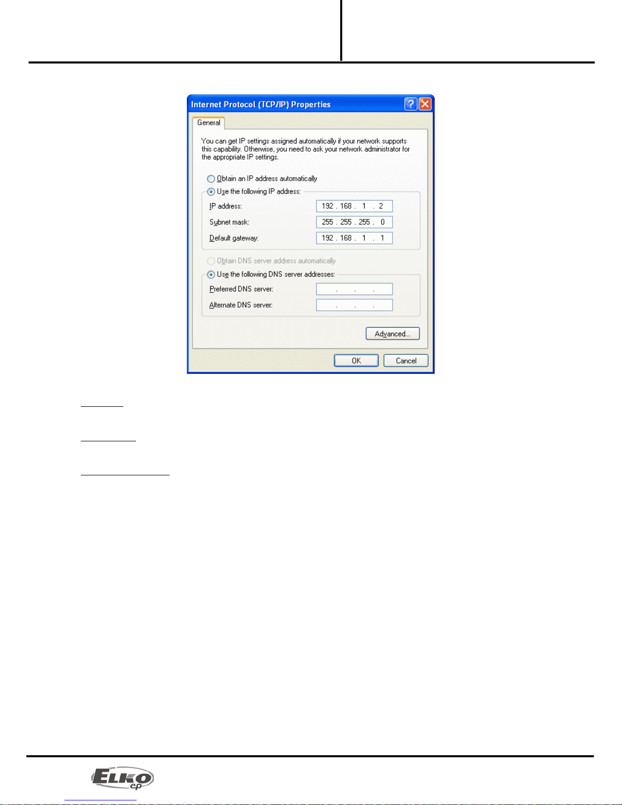
4. Perform configuration by choosing the tab Use the following IP address:
Enter the following settings into the text field:
IP Address: Set the IP address of your computer in dotted decimal notation, ex. 192.168.1.2 (where 2 is any value
from 2 to 255).
Subnet Mask: Address code that determines the size of the network. The value 255.255.255.0 is commonly used for
the subnet mask.
Default Gateway: Here enter the address of the product IP eLAN-RF-003 in dotted decimal format separated by
periods (default setting: 192.168.1.1).
The address of the DNS server need not be entered.
5. Save the settings by confirming - click OK

11/25
Converter Ethernet to RF signal
eLAN-RF-003 Configuring the iMM Client:
Installation Manual
02-040/2012
6. Configuring the iMM Client:
To configure the iMM Client in the Linux system, proceed according to the following instructions:
In the main panel in Linux, run the setting "Connect to a network ".
In the tab Wired connections add new connection by clicking on the button "Add".
Give the new connection a name.
Open the tab "IPv4 settings" choose the settings method to "Manual". After pressing the button "Add" write into
the dialog window "Addresses" the settings of the address, network masks and gateways.
Enter the following settings into the text field:
Address: Set the IP address of your computer in dotted decimal notation, ex. 192.168.1.2 (where 2 is any value from 2
to 255).
Network mask: Address code that determines the size of the network. The value 255.255.255.0 is commonly used for
the network mask.
Gateway: Here enter the address of the product IP eLAN-RF-003 in dotted decimal format separated by periods
(default setting: 192.168.1.1).
The address of the DNS server need not be entered.
Save the settings by pressing the button"Apply".

12/25
Converter Ethernet to RF signal
eLAN-RF-003 Configuration of the eLAN-RF-
Installation Manual
02-040/2012
7. Configuration of the eLAN-RF-003:
The eLAN-RF-003 device can be configured in two ways.
Configuration via USB and configuration SW ( eLAN-RF-003 Configurator)
Using the configuration SW, as opposed to configuration via Ethernet, you can set the router mode,
repeater mode, set the RF address filter and generate RF commands to the web server environment. It is not
possible however to create a visualization panel of the eLAN-RF-003 web interface. This must be created in
the web server environment.
Configuration via Ethernet connection
This configuration is sufficient for using a single eLAN-RF-003 device in connection with the iMM Client. In
the web server environment you can simply set the visual page of the control panel.
8. Configuring the eLAN-RF-003 using the SW eLAN-RF-003 Configurator:
By configuring via USB and configuration SW ( eLAN-RF-003 Configurator) it is possible to:
◦set the login data
◦set network connection parameters
◦set function of repeater and router + filter limitation to these functions
◦generate RF commands to the web server environment
Using the Ethernet connection configuration and web server, it is possible to:
◦set the login data
◦set network connection parameters
◦set parameters of the control and visualization panel
◦create an appearance of the visualization panel (inserting and placing icons, etc.)
The configuration software can be downloaded for free from the Website
http://www.elkoep.com/download/software/ . The program is used to easily configure the eLAN-RF-003 device. The
configuration SW communicates with the eLAN-RF-003 along the Ethernet network. This SW need not be installed; it
suffices to simply run it. You need to have the Microsoft package installed to run the SW.

13/25
Converter Ethernet to RF signal
eLAN-RF-003 Configuring the eLAN-RF-003
Installation Manual
02-040/2012
8.1 Administrator login:
In the login dialog window, write in the administrator login data (same as logging in to the web server
eLAN-RF-003). If you enter the wrong login data, it will not be possible in the on-line mode to change or
read settings from the eLAN-RF-003 device.
8.2 LAN parameters:
In the dialog window of the IP address and port, enter the parameters of the connected product eLAN-RF-003.
Note:
For logging into the program eLAN-RF-003 Configurator, the same rules apply as for logging in to the web
server. That means a correctly set-up network and correctly written login data. Successful connecting and
correct login may be checked in the information window.
8.3 About the device:
The window About the device indicates the connection status, login and version of SW and HW of the
product eLAN-RF-003.
The connection status is not dependent on correct login. The status "Connected!" occurs under the
condition of a correct network connection, login "Successful!" occurs after correctly entered login data.
8.4 Buttons:
Read settings:
The button Read settings reads all settings stored in the eLAN-RF-003. Reading will be successful only in the
event of successful connection and login.
Save settings:
The button Save settings saves all settings of this configuration program into the product eLAN-RF-003.
Offline mode:
Offline mode is used for easy browsing of the program options or to prepare settings prior to the actual
recording into the eLAN-RF-003 device. The settings can be completely prepared in off-line mode, and you
then only connect the eLAN-RF-003 device, and by clicking on the button Save settings, you record all of
the settings.
Attention! The previous setting will be overwritten.
Language:
Choice of language.
Web server:
The default Internet browser starts with the eLAN-RF-003 web server
Information about the device and program including hypertext links to the product manual and catalog
list.

14/25
Converter Ethernet to RF signal
eLAN-RF-003 Configuring the eLAN-RF-003
Installation Manual
02-040/2012
8.5 Device settings:
8.5.1 Basic settings.
Login: the eLAN-RF-003 distinguishes two types of login - administrator and user login. The administrator of
this device can change all settings. The user login only serves for the option of controlling the eLAN-RF-003
using the web server visualization panel.
To change the login data, write the new login name and password into the text fields. You must confirm the
password.
LAN parameters:
To change parameters of the network connection of the eLAN-RF-003, write in the new IP address,
subnetwork mask and Epsnet port into the text fields.
IP address - enter the new IP address of the product eLAN-RF-003 in dotted decimal format separated by
periods (default setting: 192.168.1.1).
Subnetwork mask - address code determining the size of the network. The value 255.255.255.0 is
commonly used for the network mask.
EPSNET port settings - is the port of the TCP/IP protocol used by the superior EPSNET protocol. Use the
factory preset port 61682. In case of problems with the firewall, we recommend choosing ports in a range
of 49152 to 65535.
Frequency band:
Here the user can choose the transmitting frequency in relation to the standard used for actuators in the
country where the eLAN-RF-003 operated. For EU, the frequency is 868.5 MHz, for Russia it is 868.1MHz and
for the USA it is 915.0 MHz.
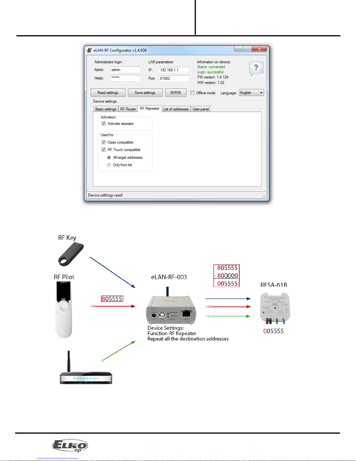
8.5.2 RF Repeater
The RF repeater function is a separate function or addition to the RF Router function.
First use: an eLAN-RF-003 device configured for a repeater can only be connected to the supply voltage,
and it will then function just the same as the RFRP-20. Therefore, if it receives a command from an RF key
alarm or RF detector, it forwards this command by RF (wireless network). The same function occurs if it
receives an OFFSET* address from (bidirectionally communicating units) RF Pilot, RF Touch, etc.
Secondary use: as an addition to the RF Router function. If two eLAN-RF-003 devices are network-
connected and the Router is required, the second eLAN-RF-003 (SLAVE) can be set as a Repeater. If the
eLAN-RF-003 device (set as a repeater) receives a command via Ethernet network or RF network, it
evaluates this command (or offsets the address) and sends it via the RF network.
Use for:
Oasis Compatible
Enables the repeater function to serve unidirectionally communicating units (RF Key, RFWB, detectors, etc.).
RF Touch Compatible
Enables the repeater function to serve unidirectionally communicating units (RF Key, RFWB, detectors, etc.).
For settings: RF Touch Compatible it is also possible to set limitations:
-Repeat all target addresses – the Repeater will repeat all addresses unidirectionally (with offset
address) and bidirectionally communicating transmitters.
-Repeat only from list – Repeater will only repeat addresses listed in the list of addresses.
15/25
Converter Ethernet to RF signal
eLAN-RF-003 Configuring the eLAN-RF-003
Installation Manual
02-040/2012

16/25
Converter Ethernet to RF signal
eLAN-RF-003 Configuring the eLAN-RF-003
Installation Manual
02-040/2012
*Offset of address
The offset of an address only concerns bidirectionally communicating transmitters (RF Touch, RF Pilot, RFAP,
etc.). Enter the address offset by the offset 0x800000 - see table for address conversion.
T
rue unit add
r
ess Address offset by the offset for
communicating via RFRP
0x xx xx 8x xx xx
1x xx xx 9x xx xx
2x xx xx Ax xx xx
3x xx xx Bx xx xx
4x xx xx Cx xx xx
5x xx xx Dx xx xx
6x xx xx Ex xx xx
7x xx xx Fx xx xx
8.5.3 RF Router
Example:
Unit address: 157600
Offset address: 957600

17/25
Converter Ethernet to RF signal
eLAN-RF-003 Configuring the eLAN-RF-003
Installation Manual
02-040/2012
The Router function is a basic use of the eLAN-RF-003 product, designed to extend the distance and control of RF
actuators by connecting two eLAN-RF-003 devices to the LAN network. The first eLAN-RF-003, also called the
MASTER, receives all RF commands of transmitters via RF. It evaluates limitations and permission of address (i.e. for
unidirectionally communicating transmitters, it sends a command to the Ethernet network directly, for
bidirectionally communicating transmitters it checks the offset of addresses*), it transfers the offset of addresses
and then sends the command to the Ethernet network. The second eLAN-RF-003 in the function of SLAVE listens to
this network and evaluates all reports from eLAN-RF-003 MASTER determined for sending via RF. It sends valid
messages via RF and waits for the response from the actuator. If a response comes from the actuator, it sends it back
to the MASTER.
Therefore, the first eLAN-RF-003 (MASTER) must be set upon configuration to the RF Router function. Where it is
necessary to set the LAN parameters of the second eLAN-RF-003 (SLAVE), such as the IP address, port
communication and the login data of the second eLAN-RF-003 (SLAVE).
The second eLAN-RF-003 (SLAVE) can be configured in two ways.
In the function of Repeater – it receives commands via Ethernet network and via the RF network. Settings
are appropriate: If a case occurs where thanks to the offsetting of the RF transmitter (control using the RF
Pilot from multiple locations) the second eLAN-RF-003 (SLAVE) catches the command, it remains in the
function of the RF Repeater (converts the address and sends a command). It does not matter from which
eLAN-RF-003 (MASTER or SLAVE) it receives the RF command. It always sends the command via RF network
of the eLAN-RF-003 set as a repeater.
Function Router and Repeater not activated – eLAN-RF-003 is in its basic setting and neither the router nor
repeater function is activated (in the SW eLAN-RF-003 Configurator you deactivate the function Router and
Repeater). The eLAN-RF-003 set up in this way only listens to commands via Ethernet network, and ignores
all commands via RF network.

18/25
Converter Ethernet to RF signal
eLAN-RF-003 Configuring the eLAN-RF-003
Installation Manual
02-040/2012
Target eLAN-RF-003 (SLAVE):
Write into this setting all parameters set to the target eLAN-RF-003 (SLAVE). If these parameters are incorrectly set,
the entire router will not function.
Use for:
Oasis Compatible
Enables the Repeater function to serve unidirectionally communicating units (RF Key, RFWB, detectors, etc.).
RF Touch Compatible
Enables the repeater function to serve bidirectionally communicating units (RF Touch, RF Pilot).
For settings: RF Touch Compatible it is also possible to set limitations:
-Repeat all target addresses. The Repeater will repeat all addresses of unidirectionally (with
offset address) and bidirectionally communicating transmitters.
-Repeat all target addresses. Repeater will only repeat addresses listed in the list of addresses.
Notice: The eLAN-RF-003 function as a router or repeater cannot operate simultaneously in one product. It is thus
necessary to create and activate just one function.
8.5.4 List of addresses:
The list of addresses tab enables choosing a list of addresses of bidirectionally communicating units, which you
want to transfer via eLAN-RF-003 repeater or router. Enter address into the address fields just as they are written on
individual products that you want to add to the list.
19/25
Converter Ethernet to RF signal
eLAN-RF-003 Configuring the eLAN-RF-003
Installation Manual
02-040/2012
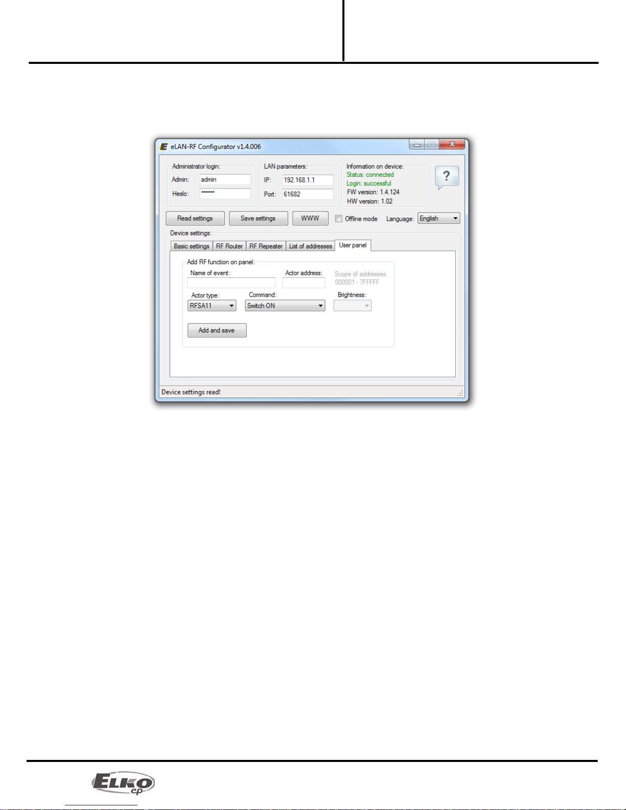
8.5.5 User panel:
The tab user panel is used to generate RF commands that the eLAN-RF-003 will perform using the panel. In this tab,
create the RF command and then by clicking on add and save, record it to the eLAN-RF-003 web interface. You can
then assign commands formed in this manner to icons on the panel in the web server environment.
Name of action (command): Here you choose the name of the action. The action will appear under this name on the
visualization panel of the web server and in the list of commands.
Actuator address: Write into the text field the address of the actuator you want.
Type of actuator: Chose from the list the type of actuator.
Command: Choose command.
Here in the list, choose the required command. Only the functions to the given actuator will be
available. The time function such as delay ON or Off can only be called up. These functions cannot be
set in the SW eLAN-RF-003 Configurator, it must already be set in the controlled actuator.
Note:
The action name is limited to 16 characters. The diacritics in the action name will be disabled. Do not use in the
action name any special characters. Generated RF commands will be displayed always after updating (rereading) the
web server builder page.
20/25
Converter Ethernet to RF signal
eLAN-RF-003 Configuring the eLAN-RF-003:
Installation Manual
02-040/2012
9. Configuring the eLAN-RF-003:
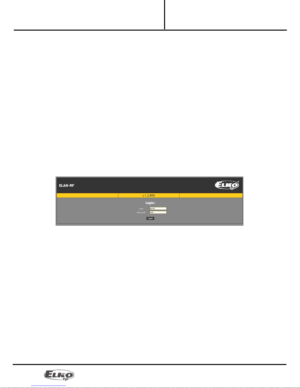
After successful configuration of the computer or iMM Client, run the web browser.
Write into the panel "Address" (in the Internet browser) the set IP address of the product eLAN-RF-003.
(Upon the first configuration, enter the factory-assigned IP address: 192.168.1.1 )
After confirming the entered IP address, the web server's login page will come up.
The initial screed displays the FW version recorded in eLAN-RF-003 (v.x.x) and login windows.
The factory setting for signing in as administrator is:
Login: admin
Password: elkoep
◦Upon the next user or administrator login, use the newly set login and password.
Login options:
◦It is possible to log into the eLAN-RF-003 web interface either as the administrator (admin) with full
access to controls and settings, or as the user (user), for whom only the panel itself is displayed. The
user thus only has the option of controlling the device (the factory setting of the password for
logging in as admin and user is: elkoep).
◦Both users log into the same dialog field (Login, password), but each uses his/her own name and
password.
Confirm login by clicking on Log in.
Note: after performing RESET on the device eLAN-RF-003 (by a long press of the button on the device front
panel), the IP address and login data are returned to factory settings.
Other manuals for eLAN-RF-003
1
Table of contents
Other Elko Media Converter manuals

Elko
Elko inels RFSG-1M User manual

Elko
Elko iNELS RFSG-1M User manual

Elko
Elko inels RFSG-1M User manual

Elko
Elko RFIM-20B User manual

Elko
Elko eLAN-IR-003 User manual

Elko
Elko iNELS RFTM-1 User manual

Elko
Elko inelsAir AirTM-100NB User manual

Elko
Elko iNELS RFSG-1M User manual

Elko
Elko RFIM-20B User manual

Elko
Elko RFIM-20B User manual


Popular Media Converter manuals by other brands


BW Broadcast
BW Broadcast rds2+ Technical manual

CHD Elektroservis
CHD Elektroservis CRX8-M installation manual

Z3 Technology
Z3 Technology Z3-SBE264-DVR-13 User instructions

CYP
CYP CSDI-12SR Operation manual

Keysight Technologies
Keysight Technologies E5053A user guide

StarTech.com
StarTech.com SLMPT2HD instruction manual