manuals.online logo
Brands
  1. Home
  2. •
  3. Brands
  4. •
  5. Daktronics
  6. •
  7. Monitor
  8. •
  9. Daktronics NPN-X200 Series User manual

Daktronics NPN-X200 Series User manual

DD5075265
Rev 00
3 June 2022
NPN-X200/X400 Series Speed Frame Substructure & Panel Quick Guide Page 1 of 4
201 Daktronics Drive
Brookings, SD 57006-5128
www.daktronics.com/support
800.325.8766
Frame Installation
Install First Frame
Note: These steps are easiest with two to three people.
1. Identify the stud locations on the wall. Use a level to draw lines the
height of the display and mark the studs.
2. Identify the position of the bottom-center frame.
3. Cut the zip ties from the rst frame. Test each bolt assembly to verify
that it slides freely.
Note: If the assembly binds, tap a hammer on the side of the steel
plate to break it loose.
4. Mark the location for the perimeter of the frame on the wall. Use this
mark to position the rst frame. Hold the frame in place on the wall and
use a 4' level on top of the frame while positioning it. Refer to Figure 1.
5. Slide the bolt assemblies to the nearest stud lines.
6. Install the supplied TEK screws (Daktronics part number HC-3979953)
through hollow bolts into the respective studs. Start with the frame
corners rst, and ll in remaining available screws. Refer to Figure 2.
Note: Do not tighten the screws.
Figure 1: Position Frame on Wall
Figure 2: Install TEK Screws in Remaining Bolt Assemblies
7. Install the brace plate (Daktronics part number 0M-4951150) after
starting a screw in the stud.
Note: Ensure that the brace plate is positioned on the screw and
lands between the wall and the tip of the hollow bolt. The
brace plate provides a strong surface to adjust the z-axis
position of the frame. If the brace plate is not placed properly,
the tip of the hollow bolt will cut and sink into the wall material.
8. Tighten the screws until the frame is xed in place.
9. Use a level on the top and side of the frame and repeat Steps 6 and 7
for the remaining bolt assemblies.
10. Place a level on the face of the vertical members in the frame to
ensure the frame is plumb and level. Adjust the Z-position of the frame
as needed. Refer to Adjust Frame Z-Position (p.1).
Note: Ensure the frame position aligns to the marked location on the
wall.
Adjust Frame Z-Position
1. Identify the bolt assembly locations to adjust away from the wall. Refer
to Figure 3.
Figure 3: Identify Bolt Assemblies to Z-Adjust
Check level on all
vertical members
2. Adjust one bolt assembly at a time.
Refer to Figure 4.
a. Loosen the TEK screw.
b. Tighten the hollow bolt into the
threaded plate until the end
of the bolt braces against the
brace plate. Continue until the
face of the frame is level.
c. Tighten the TEK screw to lock the
Z-position in place.
12
1: Sheetrock
2: Backer plate
3: TEK screw
4: Fully adjusted bolt
5: Hollow bolt
6: Threaded plate
4
5
3
6
Figure 4: Adjust Z-Position of Bolt
Assembly
DD5075265
Rev 00
3 June 2022
NPN-X200/X400 Series Speed Frame Substructure & Panel Quick Guide Page 2 of 4
201 Daktronics Drive
Brookings, SD 57006-5128
www.daktronics.com/support
800.325.8766
Install Next Adjacent Frame in First Row
1. Position the adjacent frame in the row next to the installed frame.
2. Install the supplied stitch bolts (HC-1842). Refer to Figure 5.
Figure 5: Install Stitch Bolts
3. Ensure the alignment tabs are ush
and even with each other. Refer to
Figure 6. Tighten the stitch bolts to
lock the tabs into place.
4. Cut the zip ties and verify that the
bolt assemblies slide freely.
5. Slide the bolt assemblies to the
nearest stud lines.
6. Use a 4' level on top of the frame to
level the frame while positioning it.
7. Repeat Steps 5–7 in Install First Frame
(p.1).
8. Repeat Steps 1–7 until the rst row is
fully installed.
9. Use a string line across the installed bottom row and adjust the
Z-position of the frames so the frame faces are all aligned to the string.
Verify the frame faces are level vertically as they are adjusted for the
string line.
Install Remaining Frames
1. Position the left frame in the next row on top of the rst installed frame.
Ensure the alignment tabs are ush and properly aligned. The mid
verticals set the X- and Y-axis positions of the frame.
2. Install the supplied stitch bolts across the horizontal seam and tighten to
lock the frame into place. Refer to Figure 7, Figure 8, and Figure 9.
Figure 6: Ensure Alignment Tabs Are
Flush & Even
Figure 7: Install Stitch Bolts across Horizontal Seam
Figure 8: Ensure Alignment Tabs Are
Flush & Even
3. Cut the zip ties, allowing the bolt assemblies to slide along the track.
4. Slide the bolt assemblies to the nearest stud locations.
5. Install TEK screws and brace plates, but do not tighten all the way.
Leave the TEK screws approximately 1/8" from tightened down.
6. Install the remaining frames while leaving the frames slightly loose from
the wall. Refer to Figure 10.
Figure 9: Lock X & Y Position
Figure 10: Install Remaining Frames
Plumb/Level Entire Display
1. Identify the wall high spot. Use a level on the face of the frame column
while adjusting the Z-position of the frame column. If a high spot cannot
be identied, start with the center-most frame column in the display.
2. Use the frame alignment tabs closest to the display corners and secure
a string line in an X pattern. Refer to Figure 11.
Figure 11: Secure String Line
3. Identify frame high points along the string line. Adjust the Z-position
toward the wall at the high points if the frames were not previously
Z-adjusted. If the high-point frame was previously Z-adjusted, adjust the
surrounding frames away from the wall to make the display face level
and plumb.
4. Tighten down the TEK screws to lock the frame Z-positions into place.
5. Adjust the frame Z-positions until the faces are aligned to the string and
the frame faces are plumb and level to each other.
DD5075265
Rev 00
3 June 2022
NPN-X200/X400 Series Speed Frame Substructure & Panel Quick Guide Page 3 of 4
201 Daktronics Drive
Brookings, SD 57006-5128
www.daktronics.com/support
800.325.8766
Install Seismic Clips
1. Place seismic clip (0M-4983082) up to the secured mounting points in
the frame. Refer to Figure 12.
Note: Ensure that the ange of the clip falls in the track opening and is
pressed against the side of the threaded clip.
2. Mark the location of one of the two holes in the clip to match the drill
with the screw hole. Remove the clip.
3. Drill a 5/32" diameter hole at the marked location.
4. Replace the clip and secure with a #10-12 x 3/8" sheet metal screw
(HC-1186) using the pre-drilled hole. Refer to Figure 13.
5. Repeat clip installation steps for all frame mounting locations in the
display.
Panel Installation
Route Power & Signal
1. Identify which panels will require power and/or signal inputs. Refer to
the contract-specic Shop and Riser Drawings for details.
2. Use the pass-through holes and notches in the frame to route the
power and signal input cables from the input to the required input
panel location prior to panel installation.
Note: Incoming power and signal cables external to the display
cannot be routed after panels are installed.
Figure 12: Position Seismic Clip Figure 13: Secure Clip Screws
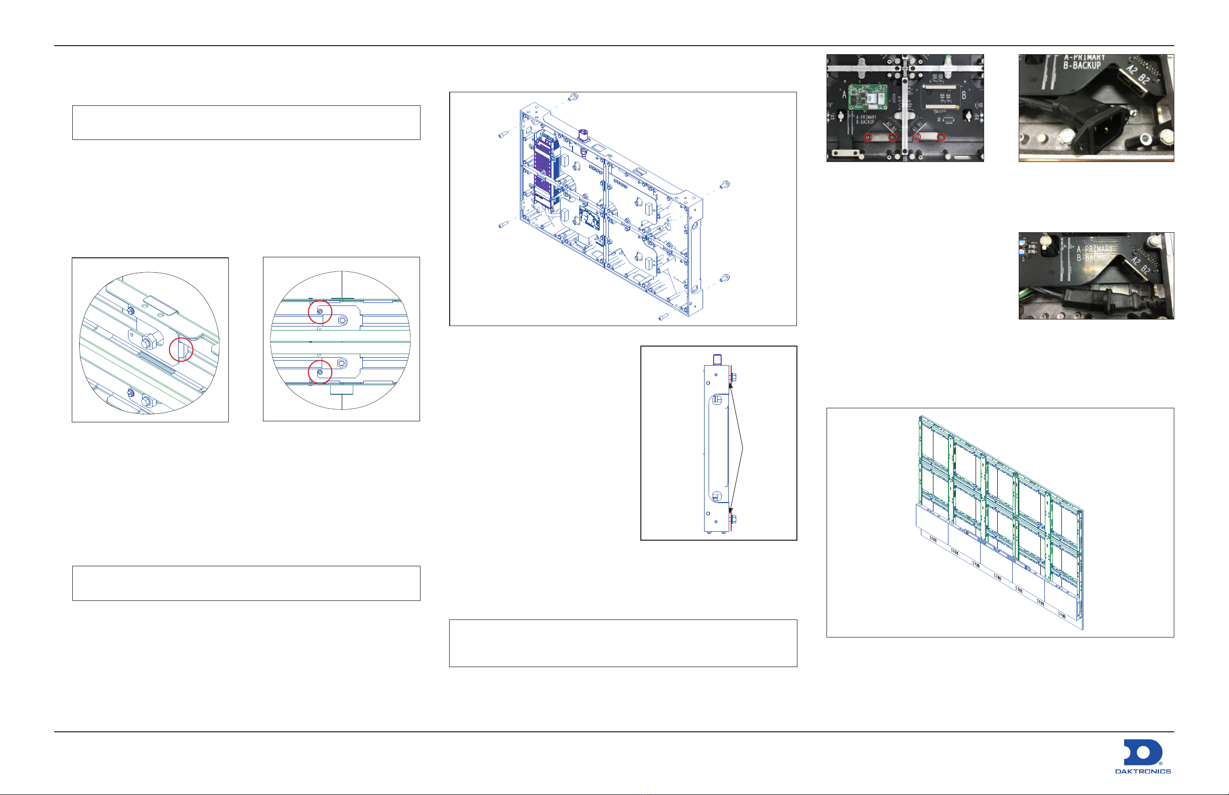
Install First Panel
1. Remove the rst panel from its packaging and install the hardware.
Figure 14: Install Hardware in First Panel
a. Install four M6 bolts (Daktronics
part number HC-1795) through
the front of the panel so the
threads are engaged but not
protruding out the rear of the
panel. Refer to Figure 14 and
Figure 15.
b. Install four M8 bolts (HC-4884317)
through the rear of the panel so
the threads are engaged but
not tightened all the way. Leave
~1/4" between the bolt ange and
the rear of the panel. Refer to
Figure 14 and Figure 15.
2. Route the Cat 6 signal cable and/
or male end of the AC power input
cable through the rectangular cutout in the panel prior to placing the
panel if installing a panel where power/signal needs to land.
Note: Depending on the structure and access to the rear of the
display, it may be very difcult or impossible to route power
cables into the panel after the panel is secured to the tube.
Figure 15: Leave 1/4" between Bolt
Flange & Panel Rear
1/4"
Figure 16: Remove Nuts from Cover
a. Remove the two nuts (circled in red in Figure 16) securing the
appropriate cover on the inside of the cabinet.
b. Use a Phillips screwdriver to
remove the two screws securing
the power cable and the
mounting bracket at the bottom
of the panel. Refer to Figure 17.
c. Install the power input cable
through the rear of the panel
and plug in the cable. Refer to
Figure 18.
3. Hang the M8 bolt heads through the keyholes in the frames to place
the panel in the bottom center-most display position.
4. Repeat Steps 1–3 for the remainder of the rst row. Refer to Figure 19.
Figure 19: Install Remaining Panels in Bottom Row
Figure 17: Remove Screws from
Mounting Bracket
Figure 18: Install Power Input Cable
DD5075265
Rev 00
3 June 2022
NPN-X200/X400 Series Speed Frame Substructure & Panel Quick Guide Page 4 of 4
201 Daktronics Drive
Brookings, SD 57006-5128
www.daktronics.com/support
800.325.8766
5. Push the panels together and verify the far-left and far-right frame
alignment tabs are not protruding beyond the display limits. Refer to
Figure 20. Shift the panels left or right as needed.
6. Start at the center of the display
and use a 5 mm hex key in the end
of the M8 bolt to tighten the panel
hardware. Level the top of the panel
while tightening.
7. Install the panel side stitch bolts
across the bottom row of panels while
ensuring the machined tops, bottoms,
and faces are all ush to each other.
Use a 5 mm key to tighten the stitch
bolts.
8. Tighten the M8 bolts in the rst row of
panels until the bolts are tight to the
frame.
9. Repeat Steps 1-3 for the remaining
panels in the display. Start at the
center of the next row up, install
the columns, and then ll in from
the bottom out from there. Refer to
Figure 21.
Figure 21: Install Remaining Panels in Display
10. Start securing panels together and to the frames at the top-center of
the display after all panels are hanging on the frames.
11. Stitch the top row of panels together, ensuring the top and machined
surfaces are ush to each other.
12. Tighten the M8 bolts so the panels are tight to the frame.
Note: Turn the M8 bolts counterclockwise to tighten and clockwise to
loosen.
Figure 20: Ensure Alignment Tabs
Do Not Protrude Past Display Edge
13. Continue to stitch panels together with stitch bolts center, down, and
out. Tighten the M8 bolts to lock the panels in place. Refer to Figure 22.
Stitch center,
down, & out
Figure 22: Stitch Panels Together
Adjust Corner Z-Position
Use M6 bolts to adjust the panel corner if a corner needs to be adjusted in
the Z-position. Use a 5 mm hex key for either bolt type.
Push Panel Corner from Structure
1. Loosen the M8 bolt in the low panel corner.
2. Tighten the M6 bolt in the low panel corner until the face is ush with
the adjacent panel.
3. Tighten the M8 bolt to lock the position into place.
Pull Panel Corner to Structure
1. Loosen the M6 bolt in the high
panel corner until the face is
ush with the adjacent panel.
2. Tighten the M8 bolt to lock the
position into place.
When all panels are installed, go
back across the faces of the corners
of the panels to ensure the surfaces
are ush. Fine-tune the Z-position as
needed. Refer to Figure 23.
Figure 23: Ensure Panel Corner Faces Are
Flush

This manual suits for next models

1

Other Daktronics Monitor manuals

Daktronics FUELIGHT FL-3000 Series User guide

Daktronics

Daktronics FUELIGHT FL-3000 Series User guide

Daktronics DSF-600 Series User manual

Daktronics

Daktronics DSF-600 Series User manual

Daktronics ST-2002 User manual

Daktronics

Daktronics ST-2002 User manual

Daktronics Galaxy AF-3050 Series User manual

Daktronics

Daktronics Galaxy AF-3050 Series User manual

Daktronics Large Matrix Galaxy GT6X Series User manual

Daktronics

Daktronics Large Matrix Galaxy GT6X Series User manual

Daktronics Galaxy AF-3165 User manual

Daktronics

Daktronics Galaxy AF-3165 User manual

Daktronics Street Furniture Guide

Daktronics

Daktronics Street Furniture Guide

Daktronics Galaxy Series User manual

Daktronics

Daktronics Galaxy Series User manual

Daktronics Galaxy AF-3400 Series User manual

Daktronics

Daktronics Galaxy AF-3400 Series User manual

Daktronics VANGUARD VC6 User manual

Daktronics

Daktronics VANGUARD VC6 User manual

Daktronics ProPixel PSX-5102-62MN-10 User manual

Daktronics

Daktronics ProPixel PSX-5102-62MN-10 User manual

Daktronics Galaxy AF-3112 Primary Series User manual

Daktronics

Daktronics Galaxy AF-3112 Primary Series User manual

Daktronics PPX-1001 Series User manual

Daktronics

Daktronics PPX-1001 Series User manual

Daktronics GALAXY GT6 Series User manual

Daktronics

Daktronics GALAXY GT6 Series User manual

Daktronics DataTime DF-1012 User manual

Daktronics

Daktronics DataTime DF-1012 User manual

Daktronics NPN-4100 Series User manual

Daktronics

Daktronics NPN-4100 Series User manual

Daktronics 65 Series User manual

Daktronics

Daktronics 65 Series User manual

Daktronics Galaxy AF-3400 Series User manual

Daktronics

Daktronics Galaxy AF-3400 Series User manual

Daktronics SW-2000 Series User manual

Daktronics

Daktronics SW-2000 Series User manual

Daktronics DVX-2821 Series User manual

Daktronics

Daktronics DVX-2821 Series User manual

Daktronics PC-2002 User manual

Daktronics

Daktronics PC-2002 User manual

Daktronics ProPixel PSX-5901-125MN-3 User manual

Daktronics

Daktronics ProPixel PSX-5901-125MN-3 User manual

Daktronics Fuelight FL-4000 Series User manual

Daktronics

Daktronics Fuelight FL-4000 Series User manual

Daktronics DF-2009 Series User manual

Daktronics

Daktronics DF-2009 Series User manual

Popular Monitor manuals by other brands

HP Z24f G3 Maintenance and service guide

HP

HP Z24f G3 Maintenance and service guide

Optiquest VS12106 user guide

Optiquest

Optiquest VS12106 user guide

Philips 190V4L user manual

Philips

Philips 190V4L user manual

Acer AL511 manual

Acer

Acer AL511 manual

NEC MultiSync E244FL Setup manual

NEC

NEC MultiSync E244FL Setup manual

LG E2350V Specifications

LG

LG E2350V Specifications

LSI GS550 user manual

LSI

LSI GS550 user manual

Dell S2440L user guide

Dell

Dell S2440L user guide

EZY SWITCH SMS-8-GPS installation manual

EZY SWITCH

EZY SWITCH SMS-8-GPS installation manual

LG L200ME user guide

LG

LG L200ME user guide

Acer M200 user guide

Acer

Acer M200 user guide

Ambu aView Instructions for use

Ambu

Ambu aView Instructions for use

Asus MG278 Series manual

Asus

Asus MG278 Series manual

Sharp TL-M5200 Setup manual

Sharp

Sharp TL-M5200 Setup manual

Panasonic VL-MC3000BX operation instruction

Panasonic

Panasonic VL-MC3000BX operation instruction

Sony PFM-42V1A Operation instructions

Sony

Sony PFM-42V1A Operation instructions

AOC e2460Swhu manual

AOC

AOC e2460Swhu manual

Seiki LC-24G82 Features & benefits

Seiki

Seiki LC-24G82 Features & benefits

manuals.online logo
manuals.online logoBrands
  • About & Mission
  • Contact us
  • Privacy Policy
  • Terms and Conditions

Copyright 2025 Manuals.Online. All Rights Reserved.