Daktronics FLR3-400 User guide

FLR3-400 Installation Quick Guide Page 1 of 4
DD2239290 Rev 03
6 August 2014
PO Box 5128 201 Daktronics Drive, Brookings, SD 57006-5128
tel: 800-325-8766 fax: 605-697-4700
www.daktronics.com
This quick guide provides steps for installing the receiver and setting up a FLR3-400 key fob with a
FuelightTM Gen 3 display.
Installing the Receiver
1. Using a flat-head screwdriver, open the digit face to
access inside the digit cabinet.
2. Remove both antenna hole plugs from the digit face.
Refer to Figure 1.
3. Place the receiver on to the mounting studs on the back
of the digit face. Refer to Figure 2.
4. Use a 5/16" nut driver to secure the receiver to the
mounting studs using the two provided nuts.
5. Place the threaded end of the antenna cable through
the antenna hole.
6. Place the flat washer over the threaded end of the
antenna cable. Refer to Figure 2.
7. Thread the provided nut on to the threaded end
of the antenna cable and tighten using an 11/32"
wrench.
8. Thread the female end of the antenna on to the
threaded end of the antenna cable and turn the
antenna clockwise until snug. Refer to Figure 2.
9. Connect the receiver cable from receiver to the
driver. Refer to Figure 3.
10. Neatly secure any excess cable with cable ties.
11. Close and secure the digit face.
Antenna Hole Plug
AH
Mounting Stud
Figure 1: Digit Door Receiver Mounting Overview
Receiver
Antenna
Mounting Stud
Nut
Digit Face
Nut Washer
Figure 2: Mounting Prole
Figure 3: Final Receiver Assembly
Digit Cabinet
Driver
Receiver
Antenna Cable
FLR3-400 Installation Quick Guide Page 2 of 4
DD2239290 Rev 03
6 August 2014
PO Box 5128 201 Daktronics Drive, Brookings, SD 57006-5128
tel: 800-325-8766 fax: 605-697-4700
www.daktronics.com
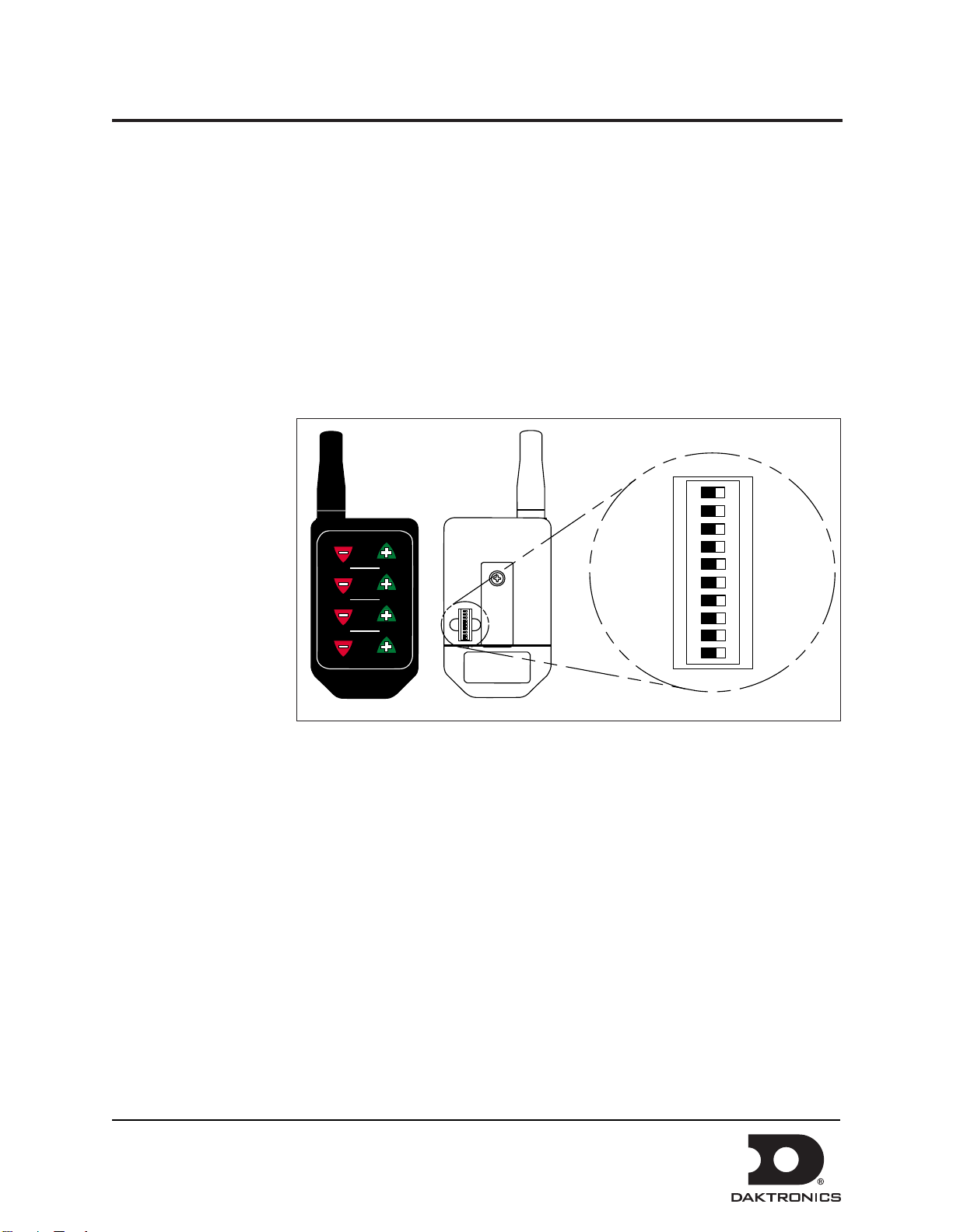
Setting the Security DIP Switches
The FLR3-400 key fob has a series of dip switches on the back to give it a unique address setting. Set these
switches to a unique setting to prevent others from being able to control your display.
1. Remove the small cover on the back of the FLR3-400 key fob radio. Refer to Figure 4.
2. Using a paper clip or a micro screwdriver, set the switches to a unique setting.
Note: Do not change switches nine and zero.
3. Replace the back cover.
Mating the Key Fob with the Display
Follow these steps to mate the display with the FLR3-400 key fob. If these steps are not completed, the
display will not recognize
or respond to the key fob.
1. Turn power on to
the display.
2. While display is
booting up, or
within 5 minutes,
press and hold
Line one Plus
(+) and Minus
(-) keys until the
decimal flashes
3 times. Refer to
Figure 4.
3. Once the decimal
point flashes 3
times, release the
buttons.
Setting the Display Line Numbers
Follow these steps to map the line number for each display. It is important that each display is set for the
correct line number for it to show the correct price.
1. Make sure the display is turned on.
2. Press and hold the -2 and +2 buttons on the key fob until the host display face begins to dim and
brighten or the decimal begins to flash. This takes about five seconds.
Note: The host display is the display with the radio antenna connected to it.
3. While the display slowly flashes, press the +2 button until the appropriate line number is shown
on the display (L01, L02, etc).
4. Once the line number is set, press and hold the -2 and +2 buttons until the next display face
begins to slowly flash.
5. Repeat these steps until all display faces have been correctly mapped.
LL-2855 REV00
CONFIG ADDR SYNC
4
3
2
LINE
1
TEST
1 2 3 4 5 6 7 8 9 0
ON
1 2 3 4 5 6 7 8 9 0
ON
Figure 4: FLR3 Key Fob

FLR3-400 Installation Quick Guide Page 3 of 4
DD2239290 Rev 03
6 August 2014
PO Box 5128 201 Daktronics Drive, Brookings, SD 57006-5128
tel: 800-325-8766 fax: 605-697-4700
www.daktronics.com
Note: If a display gets set incorrectly, complete the process with the remaining displays then
repeat to correct.
6. Exit configuration mode by pressing and holding the -2 and +2 buttons until the displays show
prices and they no longer flash; about five seconds.
Note: All displays are programmed with a default price matching their line number. Use this to
easily identify that all displays are addressed correctly.
Number Conguration
This section steps you through configuring the numbers six
and nine and the fraction display preferences.
1. Make sure display is turned on.
2. Press and hold the -3 and +3 buttons on the key
fob until all displays show the numbers 6 and 9.
The number scheme will be either 3.69 9/10 or 4.69
9/10. Refer to Figure 5.
3. Press the Plus (+) or Minus (-) keys to scroll
through the different configuration options.
Note: For Domestic displays with a 9/10s digit, the
number 3 needs to show in the first column for the
desired format. For International displays, make
sure the number 4 shows in the first column for the
desired format.
International displays offer two configuration
options - tails and 9 and no tails and 9, as shown in
Figure 6.
4. When the desired configuration is shown on the
displays, press and hold the -3 and +3 buttons to
exit configuration mode.
Entering Test Mode
Entering test mode causes the displays to cycle through
various pieces of information that can be useful when
working with Daktronics Technical Support.
1. Press and hold the Plus (+) and Minus (-) keys
on line four of the key fob until the displays
begin cycling through test mode.
2. Exit test mode by pressing and holding the Plus (+) and Minus (-) keys on line four until the
displays return to showing prices; approximately five seconds.
No Tails and 9
No Tails and 9/10
Tails and 9
Tails and 9/10
Figure 5: Digit Congurations
No Tails and 9
Tails and 9
Figure 6: International Digit Conguration

DD2239290 Rev 03
6 August 2014
PO Box 5128 201 Daktronics Drive, Brookings, SD 57006-5128
tel: 800-325-8766 fax: 605-697-4700
www.daktronics.com
AH
GEN III FUELIGHT
RISER DIAGRAM; FLR3-400
LSOPER 12 SEP 12
P1611 R 01 A
NONE
LSOPER
1113268
01
1 OF 1
3
2
1
LINE
SYNCADDRCONFIGTEST
4
LL-2855 REV00
FUELIGHT DISPLAY
MD
MAIN DISCONNECT
OVERALL SIGN STRUCTURE
SEE NOTE 4 A&B FUELIGHT DISPLAY
1. POWER FEEDER SIZED AS NEEDED, BY CUSTOMER.
ALL WIRING TO MEET OR EXCEED LOCAL AND
NATIONAL ELECTRICAL CODES.
2. 2 KNOCKOUTS PROVIDED FOR 3/4" CONDUIT
FITTING ON REAR OF DISPLAY FOR POWER AND
SIGNAL ENTRANCE.
3. REFER TO MANUAL FOR LINE-TO-LINE WIRING
BETWEEN DISPLAYS.
4A. INSTALL OPTIONAL QUICK CONNECT PANEL IN
THE SIGN STRUCTURE NO MORE THAN 8 FEET FROM
THE DISPLAY DRIVER. DRILL 7/8" HOLE IN SIGN
STRUCTURE TO PASS CONNECTIONS THROUGH. USE
INCLUDED BUSHINGS WHERE APPLICABLE.
4B. RUN OPTIONAL QUICK CONNECT CABLE
PROVIDED WITH DIRECT ACCESS PORT THROUGH
3/4" CONDUIT TO THE SIGN STRUCTURE. SEE JBX
WIRING TABLES FOR WIRE TERMINATIONS.
4C. OPTIONAL DIRECT ACCESS PORT KIT NOT
INCLUDED IN FLR3-400 KIT.
4D. OPTIONAL WIRED CONTROLLER NOT INCLUDED IN
FLR3-100 KIT OR DIRECT ACCESS PORT KIT.
4E. JBX2 CONNECTION IS NOT TO BE USED WITH A
LAPTOP.
5. SEE DWG-1092852 FOR OPTIONAL DIRECT WIRED
COMM OPTION AND WIRING DIAGRAM.
6. ADDITIONAL PYLONS REQUIRE ADDITIONAL
FLR3-400 KITS.
JBX2
400FT MAX
COMPONENT IDENTIFICATION TABLE
COMPONENT DESCRIPTION PROVIDED BY INSTALLED BY
DRIVER FUELIGHT DRIVER DAKTRONICS FACTORY
MD MAIN DISCONNECT CUSTOMER CUSTOMER
KEYFOB REMOTE KEYFOB REMOTE DAKTRONICS CUSTOMER
REC KEYFOB REMOTE RECEIVER DAKTRONICS CUSTOMER
JBX2 OPTIONAL JBOX, DIRECT ACCESS PORT DAKTRONICS CUSTOMER
CTRL OPTIONAL WIRED DM-100 PRICE/T&T CONTROLLER DAKTRONICS CUSTOMER
ANT KEYFOB REMOTE RECEIVER ANTENNA, FLR3-400 DAKTRONICS CUSTOMER
CABLE IDENTIFICATION TABLE
ID TAG DESCRIPTION PROVIDED BY INSTALLED BY
AOPTIONAL QUICK CONNECT PNL MNT TO 6 POS MINI MNL, 8FT DAKTRONICS CUSTOMER
BHARN; 6 PIN MINI MNL TO 6 PIN MINI MNL, 5FT DAKTRONICS CUSTOMER
CCABLE:ANTENNA:RP-SMA FEM BULKHEAD TO RP-SMA MAL,12 DAKTRONICS CUSTOMER
DPOWER FEEDER SEE NOTE "1" CUSTOMER CUSTOMER
EHARN; 6 POS QUICK CONNECT TO WHIP, 50FT (NOT INCLUDED) DAKTRONICS CUSTOMER
FCABLE; RS232 DB9 MALE TO DB9 FEMALE, 10FT DAKTRONICS CUSTOMER
GCABLE; LINE TO LINE; 4 POS MINI MNL, 15 FT DAKTRONICS CUSTOMER
NOTES:
DRIVER
D
A
B
DRIVER
CREC
CTRL (SEE NOTE 4D)
F
E
DIRECT ACCESS PORT
KIT
(NOT INCLUDED)
SEE NOTE 4C
KEYFOB REMOTE
(INCLUDED)
G
ANT JBX2 WIRING TABLE CABLE E
BLK
WHT
TB3-2
TB3-3
TB3-4
GRN
TB3-1 RED
01 20 SEP 2013 JJL
ADDED JBX WIRING TABLE
Table of contents
Other Daktronics Radio manuals


