Daktronics FLXR4 User manual

FLXR4 Server and Client Radio Installation
Procedure Quick Guide
DD4601945
Rev 01
14 May 2021
201 Daktronics Drive
Brookings, SD 57006-5128
www.daktronics.com/support
800.325.8766
Page 1 of 8
Server Radio Kit
Letter Component Type
A Pole-Mount Hardware
B Wall Pack Transformer
CAntenna Extension Cable - 50'
D DIN Rail Mount/Track
E 900Mhz Server Radio
F Antenna Adapter
G High Gain Antenna
HServer to DM-100
Interconnect Cable - 10'
I DM-100 (Existing)
Indoor Server Radio Installation
1. Mount the 900Mhz Server Radio (E) and wall pack transformer (B).
2. Feed Interconnect cable (H) between Server Radio (E) and DM-100 (I).
Warning: Applying Power to the radio without an attached antenna may cause damage!
Exterior Server Radio Antenna Mounting
1. Mount High Gain Antenna (G) using mounting hardware (A) on the
outside of the building housing the server radio. Mount the antenna
as high as possible in free air. Locate the antenna within 50 feet of
the server radio location. Refer to Figure 4.
There are two antenna mounting options:
• U bolts for pole mounting
• Brackets for wall mounting
2. Interconnect the antenna extension cable (C) between the antenna
(G) and server radio (E).
B
AC
D
EF
GHI
Figure 1: Server Kit Components
H
Figure 2: DM-100 Interconnect
Cable
From
DM-100
To Wall
Pack
Figure 3: Server Radio Connections
Figure 4: Mounted Antenna

FLXR4 Server and Client Radio Installation
Procedure Quick Guide
DD4601945
Rev 01
14 May 2021
201 Daktronics Drive
Brookings, SD 57006-5128
www.daktronics.com/support
800.325.8766
Page 2 of 8
3. Connect the adapter (F) to the antenna (G).
4. Use the tape provided in the
mounting kit to wrap and protect
the antenna interconnect. Refer to
Figure 5 and Figure 6.
5. Connect wall pack transformer (B) to
server radio (E).
Warning: Applying Power to the radio
without an attached antenna may
cause damage!
6. Record the server radio ID. This is
shown during boot up and will be
necessary to set up communication
to Client radios.
Client Radio Installation
Install the client radio using one of the methods below.
1. Mount the Client radio box on
the exterior of the display with the
antenna directly connected.
2. Mount the Client radio box inside of
the overall display structure (hidden)
with the 10' bulkhead cable routed to
the exterior. Refer to Figure 7.
3. Mount the Client radio box within the
inside of the Fuelight display.
a. Mount the antenna in a optimal
location that is elevated further
off the ground, has improved line
of sight to the server radio
antenna, and within 10 feet of the
client radio. Daktronics provides a
10' antenna extension cable to
allow for optimal antenna placement. Refer to Figure 8.
b. Use the same tape on the
server antenna terminations on
this bulkhead/extension cable
termination.
c. Terminate the antenna cable to
the client radio enclosure and
attach the antenna.
Warning: Applying Power to the radio without an attached antenna may cause damage!
4. Install the power adapter harness W-4582582 that was shipped with the FLXR4 Client Radio. Refer to
Figure 10.
Figure 5: Adapter Attached to
High Gain Antenna
Figure 6: Connect Extension
Cable to Radio
Figure 7: Radio Enclosure and
Antenna Figure 8: Optimum Radio
Mounting Location
Figure 9: Setting Client Radio
Number
Figure 10: Power Adapter
Harness

FLXR4 Server and Client Radio Installation
Procedure Quick Guide
DD4601945
Rev 01
14 May 2021
201 Daktronics Drive
Brookings, SD 57006-5128
www.daktronics.com/support
800.325.8766
Page 3 of 8
Client Radio Set Up
By default, each client defaults to SU#1 and the Network number defaults to a unique ID. Congure
each client radio in sequence by completing the following steps:
1. Every client radio must have a unique SU number. Change the client radio number by pressing the
reset button, shown in Figure 9, for 5 seconds to enter conguration mode.
The LCD shows display “SU #X”. X represents the current client radio number.
2. Press the button to increment the client unit number.
3. Repeat as necessary until reaching the desired client unit number.
• Client units automatically roll over from 4 to 1.
• Currently, client radios can be numbered 1-4 only.
4. Wait about 15 seconds until the LCD shows “SU ID set to X”. This
message remains on the LCD for about 5 seconds.
After 5 seconds, the LCD shows “CH #Y”. Y represents the current
channel number (1-18 or Auto).
5. Set the client radio to CH AUTO. The options are CH #1-18 and CH
AUTO. On power up, the radio scans through the channels until it
nds a server it can talk to.
• This is the preferred method.
• The LCD shows “Ch #” set to “X”.
Notes:
A Network Number is unique for each installation site and prevents networks located close to one another
from interfering with each other. For example, if two installations are across the street from one another, one
site could be set to network 1 and the other site set to network 2. Each Network Number is unique to each
site and is obtained from each Server Radio’s Unique ID Number at boot-up or through network login.
Set the network number on Client Radio to the radio ID of the server radio recorded in Exterior Server Radio
Antenna Mounting (p.1) step 6. Refer to Figure 11 and Figure 12.
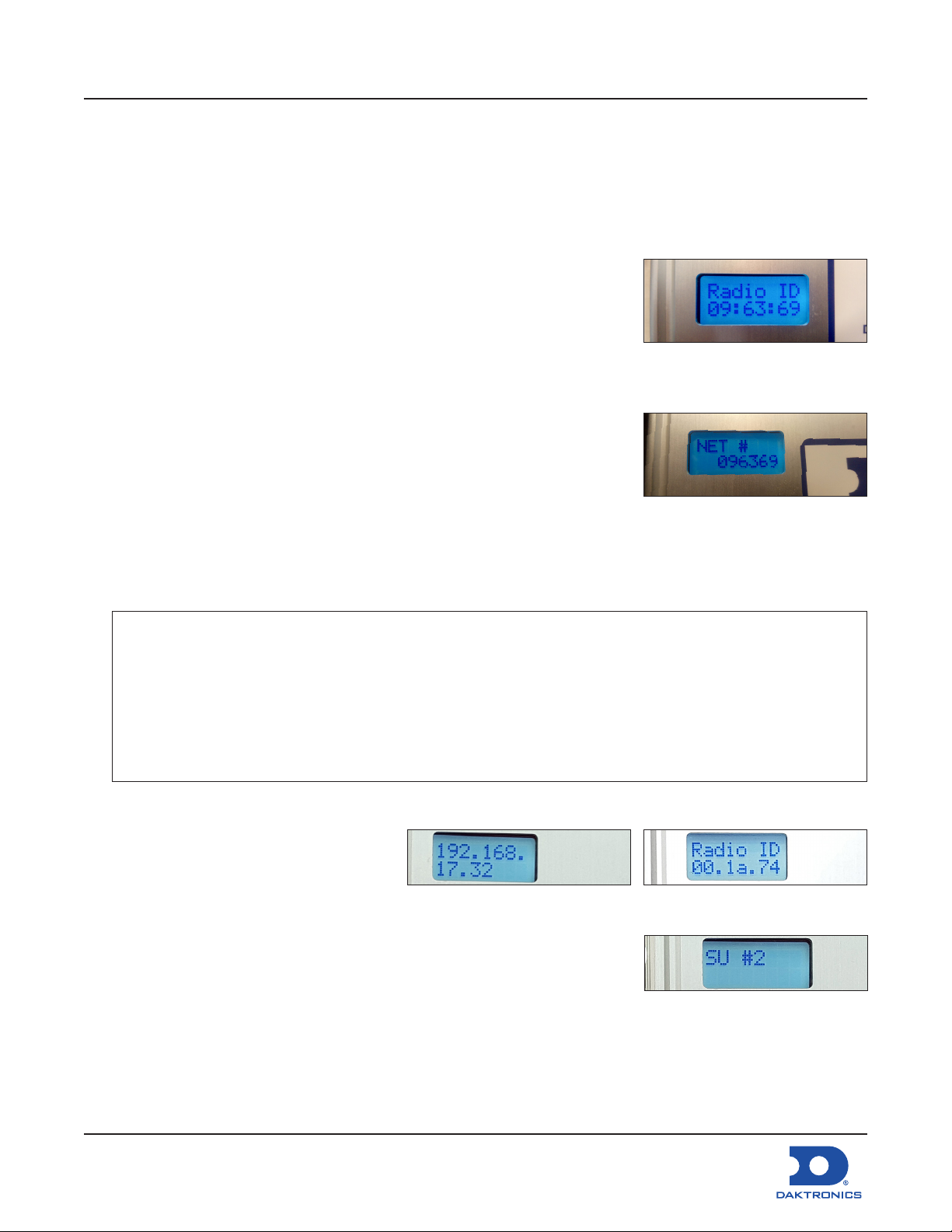
6. After 5 seconds, the LCD shows “NET #Y”. Y represents the current network number.
• The network number is 6 digits
and pressing the button loops the
current digit (indicated by pulsing
cursor) 0-9. Refer to Figure 12.
• Wait 5 seconds to move to the
next digit.
7. Repeat as necessary until reaching the desired network number.
8. Wait about 15 seconds until the LCD shows “NET # set to Z”.
Figure 11: Server Radio ID
Number (unique to each site/
server)
Figure 12: Set Network Number
on Client Radio from Server
Radio ID Number
Figure 13: Client Radio IP Address Figure 14: Client Radio ID
Figure 15: Client Subscriber Unit
Number

FLXR4 Server and Client Radio Installation
Procedure Quick Guide
DD4601945
Rev 01
14 May 2021
201 Daktronics Drive
Brookings, SD 57006-5128
www.daktronics.com/support
800.325.8766
Page 4 of 8
9. While the radio reboots, use the following table to note the IP address (Figure 13), radio ID number
(Figure 14), and subscriber unit number (Figure 15) for each client which is unique to each site.
Radio IP Address Radio ID Number Client Unit Number
Following successful boot up, client units show signal strength.
Note: Signal strength will not show until the server radio is setup with
client ID and sequence.
Server Radio Set Up
Congure the server radio through a web
interface by attaching an Ethernet cable from the
radio to a computer and completing the following
steps.
1. Click the Table tab.
2. Congure the computer’s IP address for the
same subnet as the radio’s IP. Open a web
browser and navigate to the radio’s IP address
(example: http://192.168.0.30).
3. Enter the radio password to gain access to the
advanced diagnostics and conguration. The
default password is password. Refer to
Figure 17.
4. Click the Radio tab. Enter the radio ID numbers
retrieve from each client server in Step 9 of
Client Radio Set Up (p.3) and shown in
Figure 14. Refer to Figure 18.
5. Set TX Power to 27dBm. Refer to Figure 18.
Warning: Applying Power to the radio without
an attached antenna may cause damage!
6. Click Apply. Refer to Figure 18.
Note: If communication issues arise, record
the Radio RSSI, Radio Total Packets,
Radio Failed Packets, and Radio
Passed Packets after more than 10
Figure 16: Bars Show Signal
Strength
Figure 17: Open IP Address in Web Browser
Figure 18: Radio Tab

FLXR4 Server and Client Radio Installation
Procedure Quick Guide
DD4601945
Rev 01
14 May 2021
201 Daktronics Drive
Brookings, SD 57006-5128
www.daktronics.com/support
800.325.8766
Page 5 of 8
manual price updates.
Quality of Service
The percentage of data received by each client
radio is shown in the Quality of Service area.
1. Verify that the quality of service of each client
radio goes to 100. Refer to Figure 19.
2. If it does not, check the installation and
conguration of the client radio.
3. After all clients are connected and working
properly, go back to the Radio tab and set
the server channel.
4. While logged in to the server, browse to the
Status tab and record the current RF channel.
Refer to Figure 20.
5. Browse to the Radio tab. Refer to Figure 18.
6. Select the RF channel from Step 4 in the
Channel drop-down list.
7. Click Apply.
Following Conguration
After the system is congured, the server radio searches for client radios. Refer to Figure 21.
Figure 22 shows what the server radio displays once one or more client radios are detected and
connected.
• The bars show the signal strength
received from the client radios.
When more than one client radio is
connected, this is an average value.
• The number shown below the
signal strength bars is a Quality of
Service percentage (the percent
of data successfully exchanged
between server and client radios). When more than one client radio
is connected, this is an average value.
• The number of client radios to which the server radio is connected is shown on the right.
RSSI Values
RSSI Values Signal Strength
-40dBm to -60dBm Signal Good
-61dBm to -75dBm Signal Fair
Figure 19: Table Tab
Figure 20: Status Tab
Figure 21: Server Radio
Searching For Client Radios
Signal Strength
Quality of Service
Number of
Client Radios
Figure 22: Server Radio
Connected to Client Radios

FLXR4 Server and Client Radio Installation
Procedure Quick Guide
DD4601945
Rev 01
14 May 2021
201 Daktronics Drive
Brookings, SD 57006-5128
www.daktronics.com/support
800.325.8766
Page 6 of 8
RSSI Values Signal Strength
<-76dBm Signal Poor–Check antennas, antenna cables, locations, height off ground, obstacles, etc.
Verify Connections
1. Verify that the number of connected clients shown on the LCD is correct.
2. Verify the Quality of service eventually goes to 100 (may take a minute or two) and stays there.
3. If either of the above verications fail, check the installation and conguration.
• Use the Quality of Service section of the Table tab to determine which client is having trouble.
• The RSSI value can be used to determine if the problem is with radio signal strength. This is an
average value of strength from all clients. Enable one client at a time to get an RSSI reading for
an individual client.
Auto Reset Feature
• The server radio resets every 30 seconds if it does not nd any client radios with which to connect.
• A client radio resets every 30 seconds if it does not nd a server radio with which to connect.
• The auto reset feature is disabled when there is a connection on the Ethernet port (when connected
with a computer).
• On initial setup, it may take a few reset cycles for all the radios to nd each other, and the Quality of
Service number may take a few minutes to reach 100 percent.
Network and Display Discovery
1. The DM-100 controller automatically begins detecting networks. Each client radio is referred to as a
network.
2. The controller discovers each network and detects its displays before moving to the next network.
This process takes a few minutes.

FLXR4 Server and Client Radio Installation
Procedure Quick Guide
DD4601945
Rev 01
14 May 2021
201 Daktronics Drive
Brookings, SD 57006-5128
www.daktronics.com/support
800.325.8766
Page 7 of 8
LCD Screen
Set Petroleum Prices
The LCD on the controller defaults to show current display settings on power up. The following text is
shown on the LCD.
LCD Screen Action
• The display toggles between these two screens.
• Press the Up and Down Arrow keys to scroll through the current setting for any of the
lines on the display.
• Press the ENTER/EDIT key to modify line settings.
See Section 8 in DD2238839 (FuelightTM FL-3000 & FL-4500 Series Petroleum Price Display & Cash/Credit
Display Manual) or Section 8 in DD2716696 (FuelightTM FL-3000 & FL-4500 Series 36" AND 48" Petroleum
Price Display & Cash/Credit Display Manual) for DM-100 operation instruction.
RADIOS DETECTED...
INITIALIZING
DISPLAYS...
STARTING DISPLAY
ADDRESSING...
STARTING
TRANSFER...
PROCESSING FILE...
PARSING FILE
RESULTS...
X NETWORKS
FOUND
NETWORK
X OF X
DETECTING
DISPLAYS...
DETECTED SIGN X
LINE X
SENDING
CONFIGURATION...
LINE - PRICE
1 ↓$X.XX 9/10
<EDIT> TO MODIFY
1 ↓$X.XX 9/10

FLXR4 Server and Client Radio Installation
Procedure Quick Guide
DD4601945
Rev 01
14 May 2021
201 Daktronics Drive
Brookings, SD 57006-5128
www.daktronics.com/support
800.325.8766
Page 8 of 8
FCC Compliance
• FCC ID: R4N-AW900G2LP
• IC ID: 5303A-AW900G2LP
This device complies with Part 15 of the FCC Rules. Operation is subject to the following two conditions:
1. This device may not cause harmful interference
2. This device must accept any interference received, including interference that may cause
undesired operation.
RF Exposure
WARNING: This equipment is approved only for mobile and base station transmitting devices. Antenna(s)
used for this transmitter must be installed to provide a separation distance of at least 21.05 cm from all
persons and must not be co-located or operating in conjunction with any other antenna or transmitter.
IC RSS-102 RF Exposure Statement
This system has been evaluated for RF Exposure per RSS-102 and is in compliance with the limits specied
by Health Canada Safety Code 6. The system must be installed at a minimum separation distance from
the antenna to a general bystander of 31.2 cm to maintain compliance with the General Population
limits.
Table of contents
Other Daktronics Radio manuals