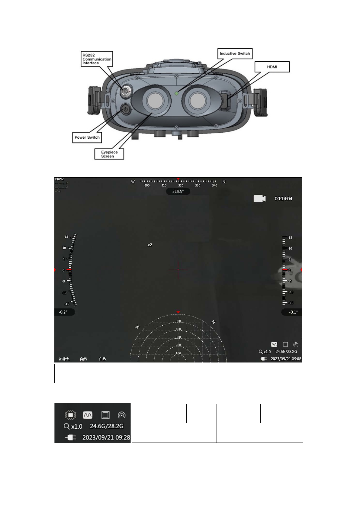
Figure 2 Bottom right status bar
Keys instruction
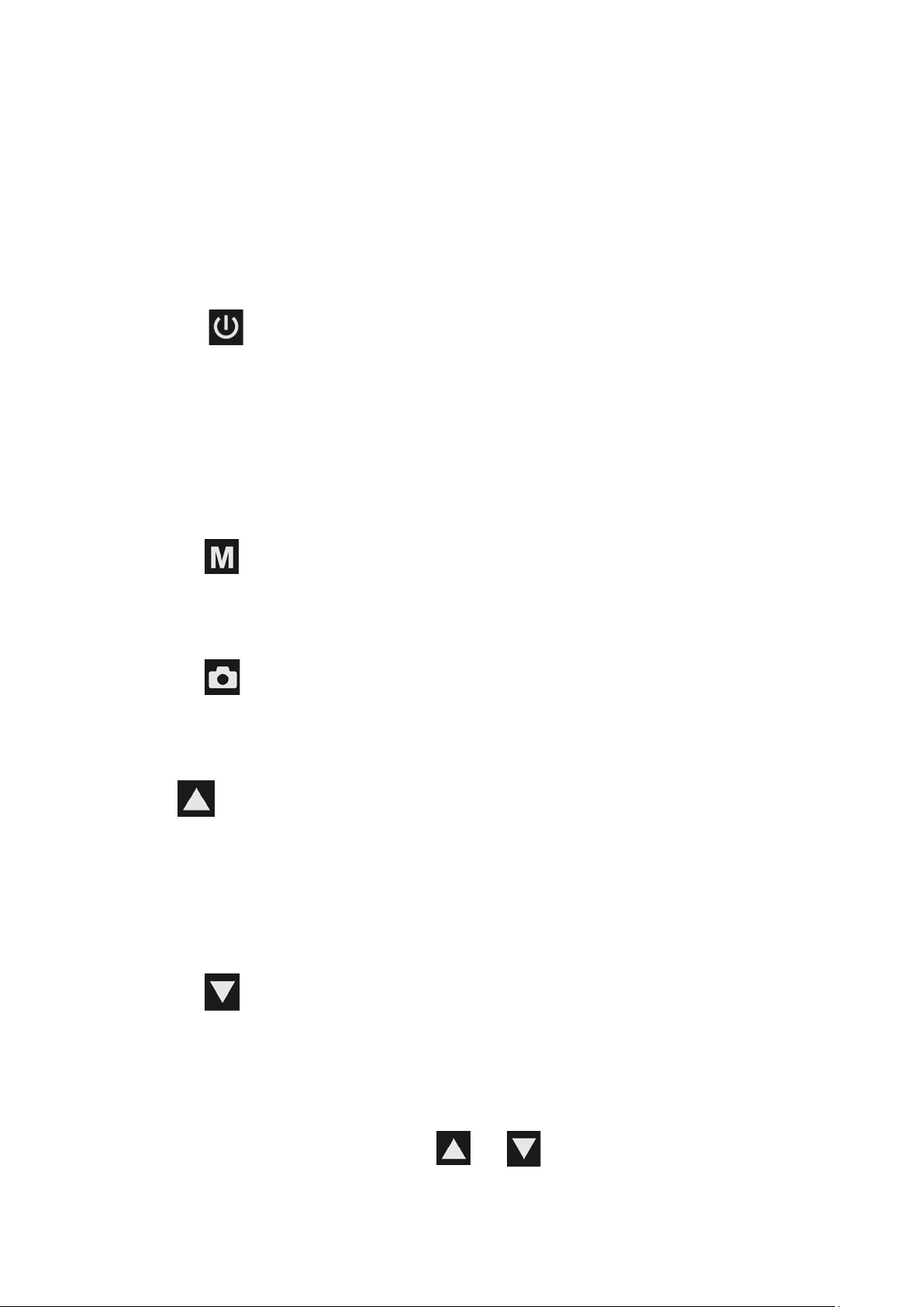
Power
Long press for 3 seconds to turn on/off the thermal imaging
camera, the green indicator light of the device is on after turning
on.
Short press for image correction, and press any key to wake up
after hibernation.
Menu
Long press to enter the main menu.
Short press to switch the image mode.
Photo
Short press to take photos.
Long press to record videos.
Up
Short press to switch between large and small field of view in IR,
short press to switch the fog mode in visible light.
Long press to zoom in under visible light, and increase focus
under IR/fusion.
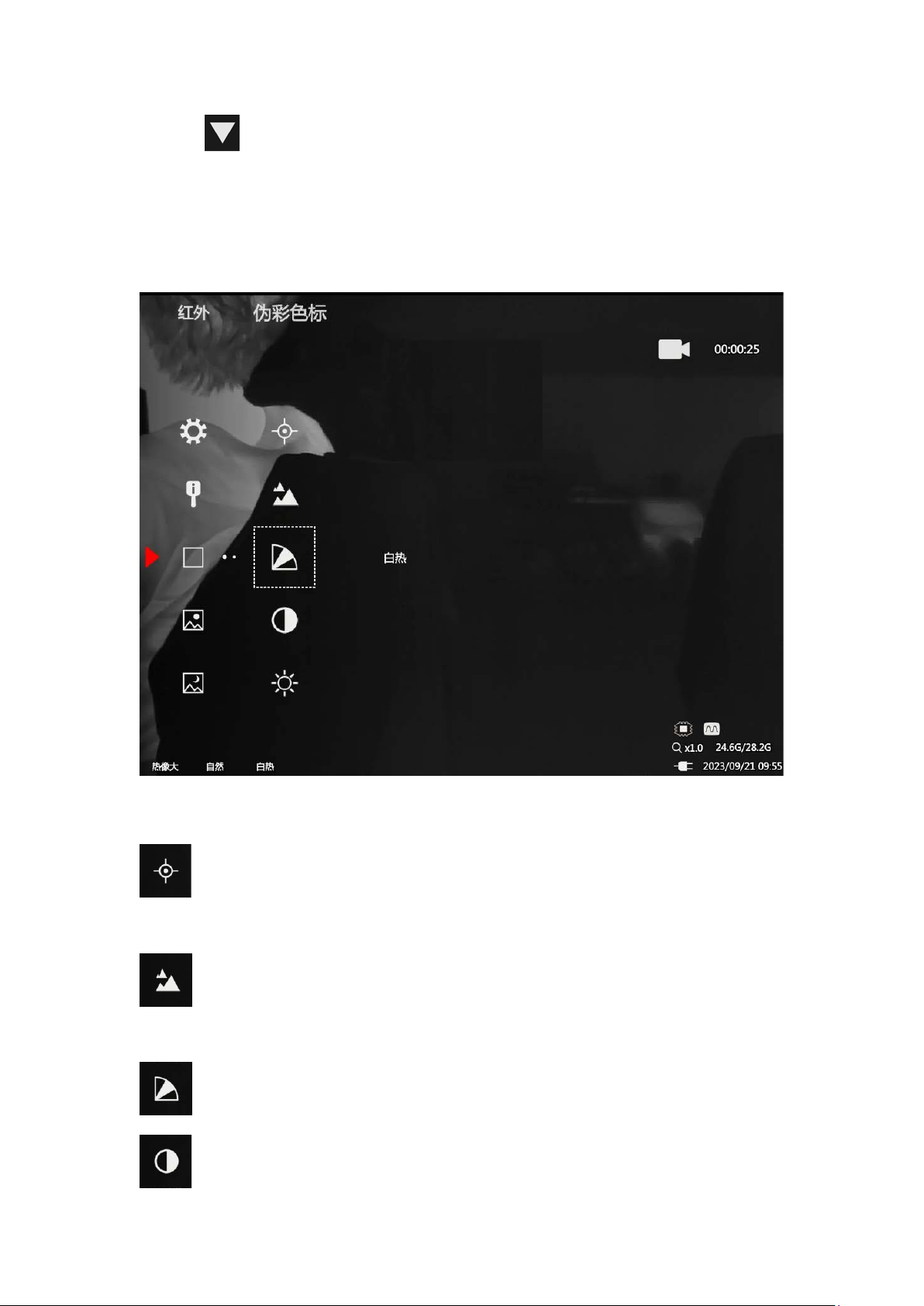
Down
Short press to auto focus.
Long press to zoom out under visible light, and decrease focus
under IR/fusion.
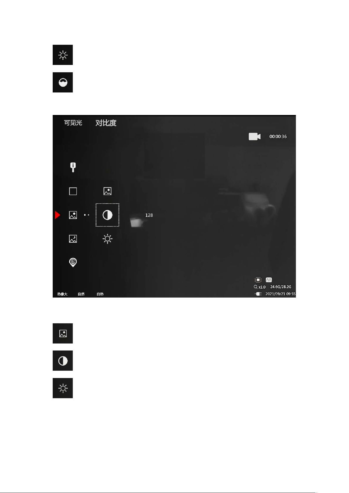
Up + Down Key Combination +