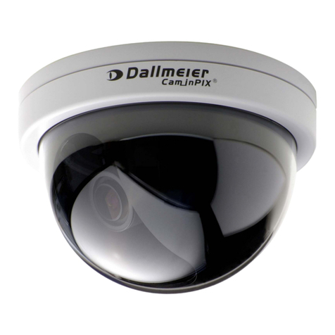
dallmeier MDF3000A-CS Operating and maintenance instructions

Installation and Configuration
Rev. 2.0.0 / 080123
English
Module cameras
MDF3000A-CS
MDF3000A-M

MDF3000A-CS / MDF3000A-M
2Dallmeier electronic
Copyright © Dallmeier electronic GmbH & Co.KG
Allrightsreserved.Thisdocumentmaynotbecopied,photocopied,reproduced,translated,
transferred to an electronic medium or converted to a machine-readable form either whole
or in part without first receiving written permission from Dallmeier electronic GmbH &
Co.KG.
We reserve the right to make technical modifications.
Themanufactureracceptsnoliability for damage to property orpecuniarydamages arising
due to minor defects of the product or documentation, e.g. print or spelling errors, and for
those not caused by intention or gross neglegence of the manufacturer.
Dallmeier electronic GmbH & Co.KG
Cranachweg 1
D 93051 Regensburg, Germany
www.dallmeier-electronic.com

MDF3000A-CS / MDF3000A-M
3Dallmeier electronic
Table of content
1 About this document.................................................................................. 5
1.1 Validity .......................................................................................................... 5
1.2 Documentation on the device ....................................................................... 5
1.3 Convention ................................................................................................... 5
2 Safety instructions ..................................................................................... 7
3 General notes.............................................................................................. 9
3.1 Scope of delivery.......................................................................................... 9
3.2 Transportation and packaging....................................................................... 9
3.3 Appropriate use............................................................................................. 9
3.4 Performance features ................................................................................... 9
3.5 Warranty ..................................................................................................... 10
4 Notes on operating the module camera ................................................. 11
5 Views and connection assignment......................................................... 12
5.1 Views .......................................................................................................... 12
5.2 Connection assignment (housing back side) .............................................. 13
6 Installation and commissioning.............................................................. 14
6.1 Requirements at the installation site........................................................... 14
6.2 Assembling mounting bracket (u-shaped) .................................................. 14
6.3 Assembling mounting bracket (z-shaped)................................................... 14
6.4 Installation................................................................................................... 14
6.5 Doing the wiring .......................................................................................... 14
6.5.1 Video- / power cable ................................................................................... 14
6.5.2 DC auto iris (MDF3000A-CS only).............................................................. 15
6.5.3 Video connection ........................................................................................ 15
6.5.4 Power connection ....................................................................................... 15
6.6 Commissioning ........................................................................................... 15
7 Preparing to configure ............................................................................. 16
7.1 UTC Remote Box ....................................................................................... 16
7.2 DMS Recorder ............................................................................................ 17
7.3 PView.......................................................................................................... 17
8 Configuration ............................................................................................ 18
8.1 Presets........................................................................................................ 18
8.2 Basic Functions .......................................................................................... 21
8.2.1 Camera ID .................................................................................................. 21
8.2.2 CCTV System ............................................................................................. 21
8.2.3 Horizontal Flip............................................................................................. 22
8.2.4 Lens Select ................................................................................................. 22
8.2.5 Color ........................................................................................................... 23
8.2.6 Day / Night Setup........................................................................................ 23
MDF3000A-CS / MDF3000A-M
4Dallmeier electronic
8.3 Image Functions ......................................................................................... 24
8.3.1 Progressive Scan........................................................................................ 24
8.3.2 Backlight ..................................................................................................... 24
8.3.3 Digital Zoom ............................................................................................... 25
8.3.4 White Balance ............................................................................................ 25
8.4 Exit Menu.................................................................................................... 26
9 Appendix ................................................................................................... 27
Menu structure ............................................................................................ 27
10 Technical data ........................................................................................... 28
10.1 MDF3000A-CS ........................................................................................... 28
Technical drawing MDF3000A-CS .............................................................. 30
10.2 MDF3000A-M ............................................................................................. 31
Technical drawing MDF3000A-M ................................................................ 33
10.3 Technical drawing mounting system ........................................................... 34

MDF3000A-CS / MDF3000A-M
5Dallmeier electronic
1 About this document
1.1 Validity
This document applies to the following module cameras:
MDF3000A-CS
MDF3000A-M
It has been produced on the basis of software version 1.7 (MDF3000A-CS) and
2.3 (MDF3000A-M).
The descriptions in this document apply to all module cameras. For simplification reasons,
the term “MDF3000A“ is thus used for all cameras.
If text passages require distinctions to be made between the different module cameras, the
complete camera name will be mentioned.
1.2 Documentation on the device
Commissioning
The quick guide headed “Commissioning“ lists the most important steps for the connection
and commissioning of the device.
Installation and Configuration (this document)
The document entitled “Installation and Configuration“ contains detailed descriptions of the
connection, commissioning and configuration of the device. General notes on the product
and technical data are additionally provided.
Thetargetaudience isexclusivelyspeciallytrainedandauthorizedprofessionals (“installers“).
Storage of documentation
Store the documents in an accessible location near the product. Keep the documents in
readable condition. Pass on all documents to each successive owner or user of the device.
1.3 Convention
This document contains various warning words and symbols that indicate potential sources
of danger. Various symbols and formats are used to maintain the clarity of the document.
DANGER
The warning word DANGER denotes an immediate danger
that may cause death or serious injury if it is not averted.
WARNING
The warning word WARNING denotes a possible danger that
may cause death or serious injury if it is not averted.
CAUTION
The warning word CAUTION denotes a possible danger that
may cause minor injury if it is not averted.

MDF3000A-CS / MDF3000A-M
6Dallmeier electronic
IMPORTANT
The word IMPORTANT denotes information for preventing
damage, incorrect configurations or incorrect actions.
NOTE
A NOTE offers information on principles, special features and
efficient procedure as well as general recommendations.
Expression Expressions in bold and italics generally indicate a control
elementonthe device (switchesorlabels)oron itsuserinterface
(buttons, menu entries).

MDF3000A-CS / MDF3000A-M
7Dallmeier electronic
2 Safety instructions
Only use this unit if it is technically in proper working order, to the intended purpose and
whilekeepingsafetyand potentialdangersinmind.Have malfunctions ordamageseliminated
immediately!
Appoint a professional
Installation, mounting, connection, start-up and configuration of the unit may only be carried
out by trained and authorized professionals (installers).
Unless otherwise expressly specified, this also applies to the maintenance, testing and
repair. In doing so the regulations of the DIN VDE 0701 series of standards (repair,
modification and inspection of electrical appliances) must be followed in addition.
Read and pay attention to the documents
Carefully and completely read the documents included in delivery. Always pay attention to
the provided instructions, notes and warnings.
Regulations surveillance systems
The use of video and audio surveillance systems is strictly regulated in most countries.
Therefore,informyourself on laws and regulations that governindividualapplicationsbefore
using the unit. Ensure compliance with these laws and regulations and also observe
regulations regarding data, working and environmental protection.
Do not make modifications
Do not make any modifications to the unit (neither to the software nor the hardware) without
consultingDallmeierelectronic.Impropermodificationscancausemalfunctionsordamages.
Dallmeierelectronicacceptsnoliabilityfordamagesresultingfromunauthorized or improper
modifications to the unit.
Protection against condensation water
If the unit is brought from a cold to a warm environment, condensation water can form
inside the unit. Short-circuits may then lead to damage to the system. Wait up to 8 hours for
the unit to reach room temperature before starting it up.
Observe the rated voltage
The unit can be damaged or destroyed by the application of an incorrect voltage.
The mains voltage must always match the rated voltage of the unit. The rated voltage is
specified on the rating plate of the unit.
Observe ratings
Unsuitableambientconditionsandimproperinstallation(mainlytoohighambienttemperature
and insufficient ventilation) may reduce the unit’s life cycle. Ensure compliance with the
stated operating conditions (see technical data), requirements at the installation site and, if
applicable, maintenance regulations.
Expansion components/peripheral devices
Useonlyexpansioncomponents conforming with the technical dataof the unit. Inappropriate
peripheral devices may result in the violation of local laws and regulations and damages to
the unit. In case of doubt, contact the sales partner responsible for your area.

MDF3000A-CS / MDF3000A-M
8Dallmeier electronic
Do not open the unit
Do not open the housing of the unit. There are no components inside the unit that require
maintenance by the user. The inspection, maintenance and repair with an open housing
must only be carried out by trained and authorized professionals (installer).
Penetration of foreign bodies and liquids
No objects or liquids may be allowed to get into the device. In this case, immediately
disconnect the unit from the power supply (pull out the power plug). Please contact the
sales partner responsible for your area.
Measures to be taken in the event of damage and burnt smell
If you notice burnt smell or formation of smoke from a unit, immediately disconnect it from
the power supply (pull out the power plug). Please contact the sales partner responsible for
your area.
Disposal
Disconnect the unit from the power supply. Remove all connected units and system
components. Return the unit to your respective sales partner.

MDF3000A-CS / MDF3000A-M
9Dallmeier electronic
3 General notes
3.1 Scope of delivery
Included in the standard scope of delivery is:
1 x Module camera with lens
1 x CD with documentation
1 x Quick Guide “Commissioning“
1 x Video- / Power cable with two ferrite clamps
1 x Mounting bracket (u-shaped)
1 x Mounting bracket (z-shaped)
3 x Slotted head screw M 4 x 6
2 x Washer 4.3 mm, galvanized
1 x Hexagonal nut M 4, self-locking
The scope of delivery may differ depending on the ordered equipment or device variant.
The device’s range of functions depends on the ordered equipment or device variant and
may therefore not correspond with this document’s content. Certain functions and features
may require an activation that is subject to costs.
3.2 Transportation and packaging
Store the original packaging for transportation at a later date. Dallmeier electronic is not
responsible for damage resulting from unprofessional/improper transportation. The goods
should only be shipped in their original packaging.
If the original packaging is no longer available, ensure that the packaging used sufficiently
protects the unit against damage, moisture, heat and cold.
3.3 Appropriate use
The MDF3000A is a high-resolution Cam_inPIX®colour module camera. It is designed for
indoor use.
3.4 Performance features
The module camera MDF3000A is especially characterised by the following functions and
properties:
z1/3’’ DPS sensor with Cam_inPIX®technology
zDigital Pixel System®chipset
z17-bit Digital Signal Processing
zHigh sensitivity for low-light image
zProgressive Scan image capture
zProgressive segmented Frame (PsF) image transfer

MDF3000A-CS / MDF3000A-M
10Dallmeier electronic
zAdvanced noise reduction
zEnhanced image quality by means of numerous control functions like AWB, AGC, BLC
and extended slow shutter
zWide dynamic range up to 120 dB
zConfiguration via UTC commands
zCompact and lightweight design
zQuick and easy mounting
zVersatile and adjustable mounting structure
zSeveral lens types available
NOTE
For detailed information, please see technical data in the
Appendix.
3.5 Warranty
The warranty period is 36 month.
The terms and conditions valid at the signing of the contract apply.

MDF3000A-CS / MDF3000A-M
11Dallmeier electronic
4 Notes on operating the module camera
The camera is powered by 12 V direct voltage.
If the camera or the cable connected to the cable is located near sources of strong
radiation, the video picture may be distorted.
The camera is equipped with automatic gain control (AGC). In low light the picture may
be altered (e.g. noise). This is not a camera malfunction.
The quality of the video image depends on the lighting and the monitor used to display
the video image.
Automatic white balance depends on the lighting used and can cause color distortions in
artificial light.
Poor lighting can lead to faulty white balance.

MDF3000A-CS / MDF3000A-M
12Dallmeier electronic
1236541 65432
Fig.5-1
5 Views and connection assignment
5.1 Views
MDF3000A-CS MDF3000A-M
1. DC auto iris lens 1. Lens
2. CS lens mount 2. Thread mount: Ø 12 mm
3. Slotted head screw M 4 x 6 3. Slotted head screw M 4 x 6
with washer 4.3 mm with washer 4.3 mm
4. Mounting bracket (u-shaped) 4. Mounting bracket (u-shaped)
5. Slotted head screw M 4 x 6 5. Slotted head screw M 4 x 6
with hexagonal nut M 4, self-locking with hexagonal nut M 4, self-locking
6. Mounting bracket (z-shaped) 6. Mounting bracket (z-shaped)

MDF3000A-CS / MDF3000A-M
13Dallmeier electronic
5.2 Connection assignment (housing back side)
Pin assignment
A = Video and power interface
Pin 1 = Video Ground
Pin 2 = Video OUT
Pin 3 = Ground
Pin 4 = +12V DC
B = DC auto iris interface
Pin 1 = Control +
Pin 2 = Control -
Pin 3 = Drive -
Pin 4 = Drive +
Connector type
A = Hirose_DF13-4P-1.25DSA
B = Molex_053047-0410
APin 1
BPin 1
APin 1
Fig.5-2
MDF3000A-CS MDF3000A-M

MDF3000A-CS / MDF3000A-M
14Dallmeier electronic
6 Installation and commissioning
6.1 Requirements at the installation site
The MDF3000A is designed for indoor use.
Unfavorable local conditions may shorten the life of the product or lead to malfunctions.
Do not install/operate the camera in places:
zwith large scale dust and dirt
zwith steam or oil vapors (e.g. kitchen)
zwith direct sunlight
zwith improper ambient temperatures (see technical data)
znear sources of strong radiation, i.e. X-rays, radio transmitters or magnetic fields
zwith corrosive surroundings (e.g. gases or salt water).
6.2 Assembling mounting bracket (u-shaped)
The mounting bracket (u-shaped) is assembled to the module camera by default.
IMPORTANT
Possible damage of camera board by using incorrect screws
or washers.
If an assembling of the mounting bracket (u-shaped) to the
module camera is necessary only use the delivered screws
andwashers.
6.3 Assembling mounting bracket (z-shaped)
¾If necessary assemble mounting bracket (z-shaped) with slotted head screw M 4 x 6 and
self-locking hexagonal nut M 4 to mounting bracket (u-shaped).
6.4 Installation
¾Assemble the module camera with mounting bracket (u-shaped) or with mounting bra-
cket (z-shaped) to the desired position.
6.5 Doing the wiring
¾Connect all necessary cables.
6.5.1 Video- / power cable
¾Connect the video- / power cable to the module camera.
IMPORTANT
Ensure the correct pin assignment.

MDF3000A-CS / MDF3000A-M
15Dallmeier electronic
6.5.2 DC auto iris (MDF3000A-CS only)
¾Connect the DC auto iris cable to the module camera.
IMPORTANT
Ensure the correct pin assignment.
6.5.3 Video connection
WARNING
Danger of death from lightning strike!
Do not connect the video cable during a thunderstorm.
¾Connect the video cable (BNC).
6.5.4 Power connection
WARNING
Danger of death from electric shock!
The power supply unit must not be connected to the power
supplywhenconnectingthepowercableofthemodulecamera.
¾Connect the power cable of the module camera to the power supply unit.
IMPORTANT
Possible damage to the camera caused by incorrect polarity.
Ensure correct polarity of the cables.
6.6 Commissioning
¾Connect the power supply unit to the power supply.
The module camera is ready for operation.
Video (BNC)
Fig.6-1
Red: 12V (+)
Black: Ground (-)

MDF3000A-CS / MDF3000A-M
16Dallmeier electronic
7 Preparing to configure
The camera is supplied with factory settings which enable it to be used for most scenarios
without further configuration. However, if required certain camera properties can be
configured using the camera menu.
The camera can be configured by means of the UTC Remote Box, the recorder or PView.
NOTE
There must be no video distributor or signal amplifier between
the camera and the UTC Remote Box (or recorder or PView).
NOTE
Refer to the separate operator’s manuals for the devices or
software used.
7.1 UTC Remote Box
Direct
Camera UTC Remote Box CVBS monitor
Via recorder
Camera UTC Recorder CVBS monitor
Remote Box
Fig.7-1
Fig.7-2

MDF3000A-CS / MDF3000A-M
17Dallmeier electronic
7.2 DMS Recorder
Camera Recorder CVBS monitor
NOTE
This method requires a recorder with software version 5.3.1 or
higher and a built-in FG-11 frame grabber card.
7.3 PView
Camera Recorder PView Station CVBS monitor
NOTE
This method requires a recorder with software version 5.3.1 or
higher and a built-in FG-11 frame grabber card, using PView
version 5.6.0 or higher.
Fig.7-3
Fig.7-4

MDF3000A-CS / MDF3000A-M
18Dallmeier electronic
8 Configuration
The configuration dialog is opened as follows:
UTC Remote Box: ¾Press the OK button for approx. 2 seconds.
DMS Recorder: ¾Select Camera control > Open / Close menu
PView: ¾Select Camera control > Open / Close menu
Navigating the configuration menu is always by means of 4 directions keys, which are
referred to as Selector in the following. The button for input confirmation and calling a
submenu is the Enter button.
Twodotsafteramenuentryindicatethatadditionalconfiguration
options are available in a submenu.
One dot means that the selected entry (command) is executed
by pressing the Enter button.
¾Press the Selector up or down ( cd) to select a menu item from the list.
¾Press the Enter button to call up the selected submenu or to execute the command.
¾Press the Selector to the right or left ( ef) to change the respective setting value.
¾To return from a submenu to the higher-order menu, select Previous Page and press
the Enter button.
NOTE
Please pay attention to chapter 8.4 Exit Menu when saving/
resetting settings already made or leaving the configuration.
8.1 Presets
The presets allow you to very easily adapt the camera
configuration to the on-site conditions to achieve the best
possible video picture.
<Universal. >is set as the preset at the factory.
The following presets are available:
Universal
Scenes full of contrast with strong backlights.The relevant details are in the highlights.
The maximum dynamic scope of the camera is used.
Large differences in brightness are adjusted.
----------------- 3000------------------
>Presets..
Basic Functions..
Image Functions..
Save / Exit Menu..
--------------- Presets----------------
Previous Page.
>Presets < Universal. >
Brightness 0
Gamma Auto
Range Bias 4
Gain Limit 28
Sharpness 1
Saturation 1
WB Offset 0 K

MDF3000A-CS / MDF3000A-M
19Dallmeier electronic
Details 1/2
Scenes full of contrast with strong backlights.
Details are displayed in high resolution.
The maximum dynamic scope of the camera is used.
Indoor / Shadow
Indoor scenes full of contrast with strong backlights.
The relevant details are in the shadow.
Detail resolution in the shadowy area is optimized.
Bright areas of the picture are displayed brighter than normal.
Indoor
Preset for indoor scenes with medium contrast.
Details are displayed in high resolution.
Detail resolution in the bright area is optimized.
Fluorescent
Use for indoor scenes with fluorescent light and low contrasts.
Detail resolution in bright areas is optimized.
Typical flickering with neon lights is compensated.
Low Light
Preset for low light scenes with slowly moving objects.
The closing and exposure time (shutter) can be adjusted manually between 2x and 8x.
NOTE
The following presets are only available in the MDF3000A
casino version.
Poker Table
ThisPresethasbeendevelopedtomeetthespecialrequirementsat the poker tableensuring
optimal identification of red and black cards.
Gambling
A preset for games that require chips.
This preset allows the chip colors to be optimally displayed.
Wheel
This Preset has been developed to meet the special requirements at the roulette wheel
ensuring optimal identification of the numbers and colors of the wheel.
Slot machine
Thispresethasbeendevelopedtomeet the special requirementsforslotmachinesensuring
optimal identification of the symbols.

MDF3000A-CS / MDF3000A-M
20Dallmeier electronic
As an alternative to the presets, the following settings can be manually changed to adapt
the camera to the prevailing conditions:
zBrightness
¾Select Brightness to adjust the image brightness.
zGamma
Gamma defines the brightness range within the color space and thus the differentiation
between lights and shadows.
¾Choose Gamma = Auto for scenarios with strongly varying light conditions.
Alternatively, the brightness range can also be set manually in 8 steps.
zRange Bias (for casino versions only)
Range Bias allows you to shade or brighten the different brightness areas.
zGain Limit (for casino versions only)
Gain Limit allows you to set the max. gain with which the amplitude of the video signal
is raised in poor light conditions.
zSharpness
¾Select Sharpness to adjust the image sharpness.
zSaturation
¾Select Saturation to adjust the color saturation.
zWB Offset
The WB Offset function can be used when the automatic white balance produces an
unsatisfactory color display with “monochrome“ scenarios. This function modifies the
metered color temperature.
This manual suits for next models
1
Table of contents
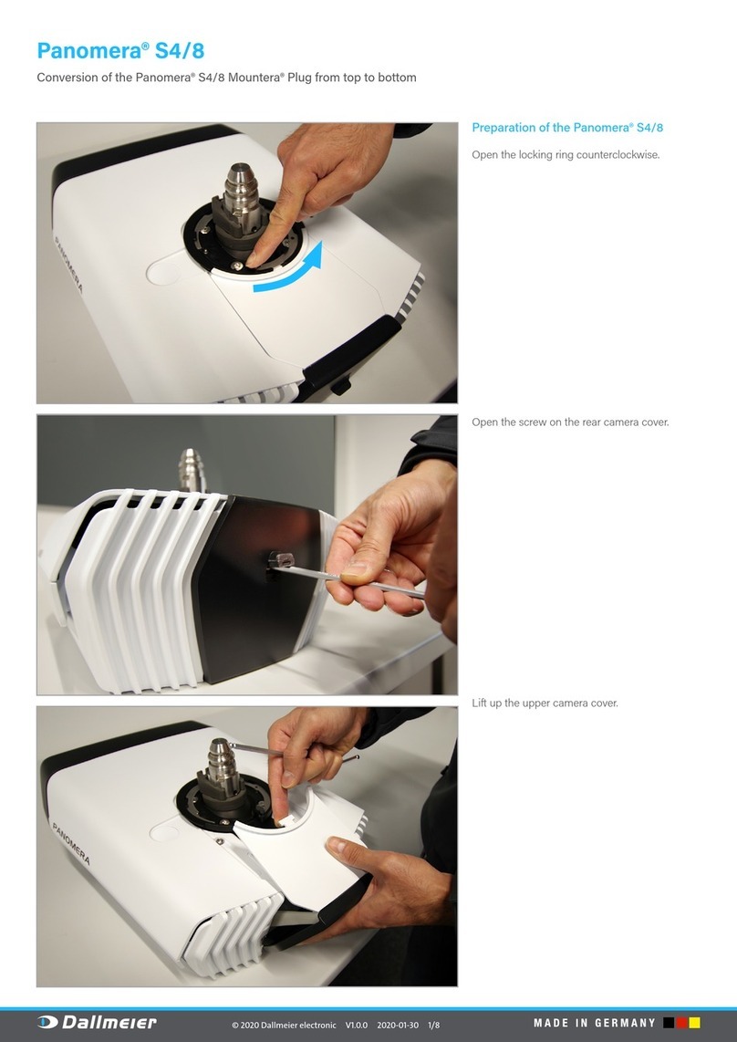
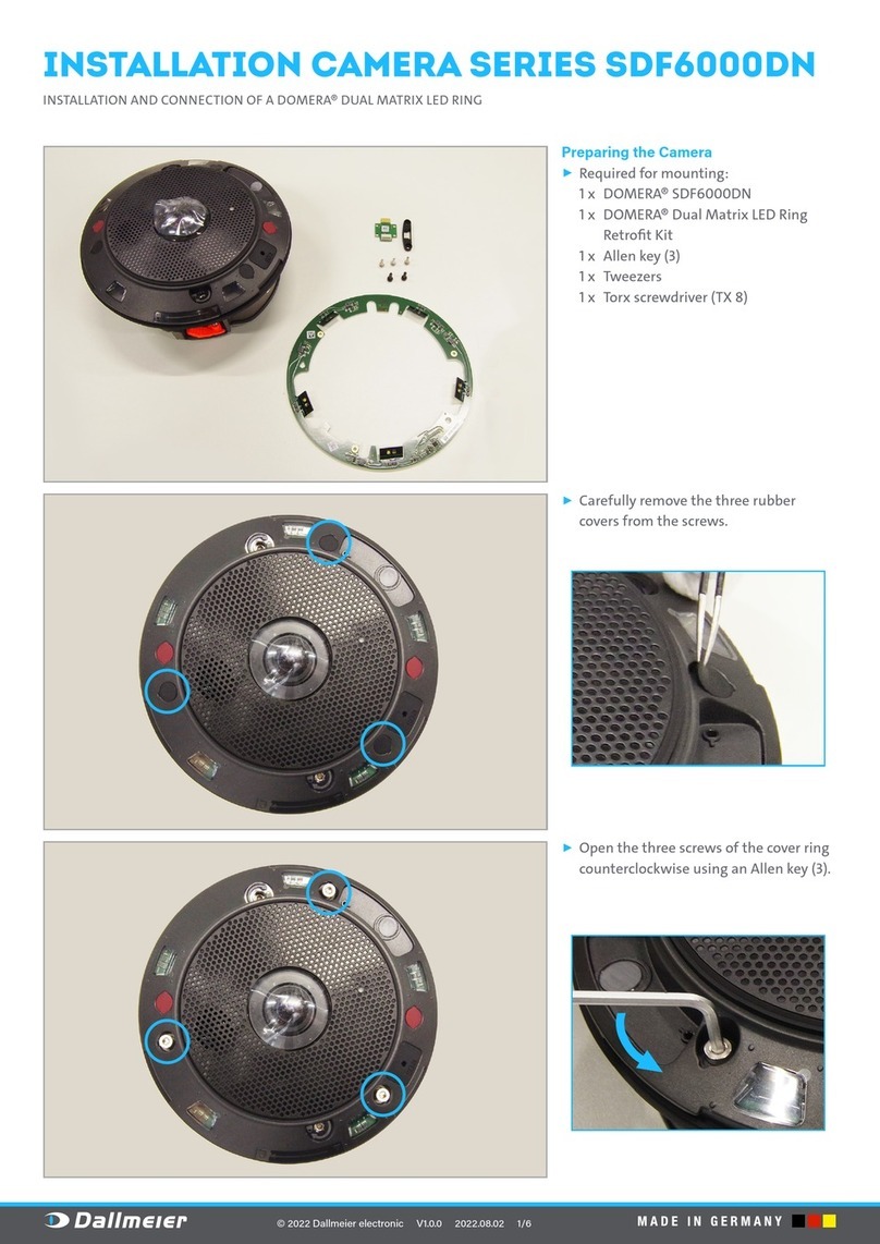
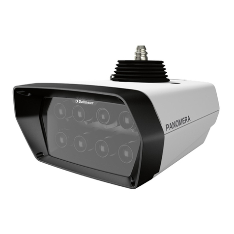
Other dallmeier Digital Camera manuals

dallmeier
dallmeier Domera DDZ3018-IM/HS Operating and maintenance instructions

dallmeier
dallmeier Panomera S4/8 User manual

dallmeier
dallmeier DDF3000A Operating and maintenance instructions

dallmeier
dallmeier MDF5450HD-DN Quick start guide

dallmeier
dallmeier SDF6000DN Series User manual

dallmeier
dallmeier Panomera S Series User manual

dallmeier
dallmeier Panomera W Series Guide

dallmeier
dallmeier RDF5000 Series User manual