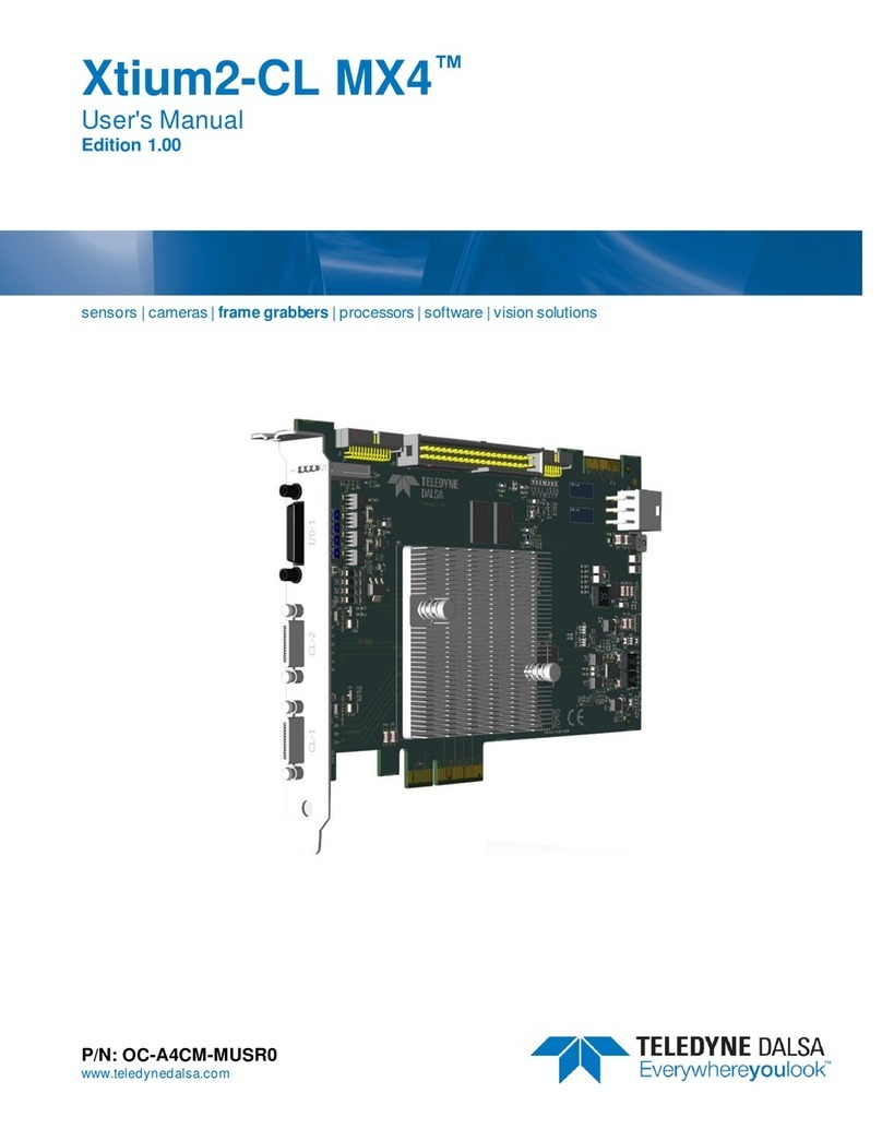
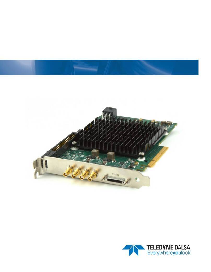
Dalsa PC2-Comp Express OC-P2EM-COMP0 User manual

DALSA •7075 Place Robert-Joncas, Suite 142 •St-Laurent, Quebec, H4M 2Z2 •Canada
http://www.dalsa.com/
*OC-P2EM-COMP0*
PC2-Comp Express™
User's Manual
Part number OC-P2EM-COMP0
Edition 2.01

NOTICE
© 2006-2010 DALSA Corp. All rights reserved.
This document may not be reproduced nor transmitted in any form or by any means, either electronic
or mechanical, without the express written permission of DALSA Corp. Every effort is made to ensure
the information in this manual is accurate and reliable. Use of the products described herein is
understood to be at the user's risk. DALSA Corp. assumes no liability whatsoever for the use of the
products detailed in this document and reserves the right to make changes in specifications at any time
and without notice.
Microsoft is a registered trademark; Windows®, Windows® XP, Windows® Vista and Windows® 7,
are trademarks of Microsoft Corporation.
All other trademarks or intellectual property mentioned herein belong to their respective owners.
Released on December 9, 2009
Document Number: OC-P2EM-COMP0
Printed in Canada

PC2-Comp Express Contents •i
Contents
INTRODUCTION................................................................................................................... 1
OVERVIEW OF THE MANUAL ............................................................................................... 1
ABOUT THE MANUAL.......................................................................................................... 2
USING THE MANUAL ........................................................................................................... 2
PC2-COMP EXPRESS BOARD............................................................................................ 3
COMPONENTS & PART NUMBERS........................................................................................ 3
PC2-COMP EXPRESS OVERVIEW ......................................................................................... 4
PC2-COMP EXPRESS FEATURES .......................................................................................... 4
PC2-COMP EXPRESS FUNCTIONAL BLOCK DIAGRAM ......................................................... 5
SAPERA LT DEVELOPMENT SOFTWARE OVERVIEW ............................................................ 6
INSTALLING THE PC2-COMP EXPRESS........................................................................ 7
WARNING! (GROUNDING INSTRUCTIONS)........................................................................... 7
SAPERA LT LIBRARY INSTALLATION .................................................................................. 7
INSTALLING THE PC2-COMP EXPRESS HARDWARE AND DRIVER ........................................ 8
In a Windows XP/Vista/7 System ................................................................................ 8
Device Manager Firmware Loader ............................................................................ 9
Firmware Update: Automatic Mode ................................................................................10
Firmware Update: Manual Mode ....................................................................................10
Executing the Firmware Loader from the Start Menu......................................................11
UPGRADING SAPERA LT OR ANY DALSA DEVICE DRIVER .............................................. 11
Device Driver Upgrade Only.................................................................................... 12
Sapera LT and Device Driver Upgrades .................................................................. 12
CONNECTING CAMERAS .................................................................................................... 13
TESTING ACQUISITIONS .................................................................................................... 15
TROUBLESHOOTING INSTALLATION PROBLEMS ................................................................ 15
Recovering from a Firmware Update Error ............................................................. 15
Windows Event Viewer.............................................................................................. 16
DALSA Device Manager Program............................................................................ 16
Information Window.........................................................................................................17
PCI Configuration..................................................................................................... 18
Sapera and Hardware Windows Drivers .................................................................. 19
Log Viewer ................................................................................................................ 20
Windows Device Manager ........................................................................................ 21
Symptoms: CamExpert Detects No Boards............................................................... 21

ii •Contents PC2-Comp Express
Symptoms: Board does not grab ............................................................................... 22
Symptoms: Board Grabs Black ................................................................................. 22
THEORY OF OPERATION ................................................................................................ 23
ACQUISITION PROCESS...................................................................................................... 23
Analog Front End...................................................................................................... 23
Onboard Memory...................................................................................................... 24
DMA Controller ........................................................................................................ 24
Events and Status ...................................................................................................... 24
Event-Related Definitions ................................................................................................25
Acquisition Events..................................................................................................... 25
External Trigger (Used or Ignored)................................................................................. 25
Vertical Sync from Camera.............................................................................................. 25
Frame Lost....................................................................................................................... 26
Start of Frame.................................................................................................................. 26
Start of Field ....................................................................................................................26
Start of Odd Field ............................................................................................................ 26
Start of Even Field ........................................................................................................... 26
End of Frame ................................................................................................................... 26
End of Field .....................................................................................................................26
End of Odd Field..............................................................................................................27
End of Even Field............................................................................................................. 27
Acquisition Status...................................................................................................... 27
Chroma Present ...............................................................................................................27
Horizontal Sync Lock ....................................................................................................... 27
Vertical Sync Lock ........................................................................................................... 27
Transfer Events ......................................................................................................... 28
End of Frame ................................................................................................................... 28
End of Field .....................................................................................................................28
End of Odd Field..............................................................................................................28
End of Even Field............................................................................................................. 28
End of Transfer ................................................................................................................ 28
EXTERNAL TRIGGER.......................................................................................................... 29
TRIGGER-TO-IMAGE RELIABILITY..................................................................................... 30
Trigger Signal Validity..................................................................................................... 30
Acquisition Or Transfer Status......................................................................................... 30
Supported Transfer Cycling Methods............................................................................... 31
TECHNICAL REFERENCE ............................................................................................... 33
HARDWARE SPECIFICATIONS............................................................................................. 33
Camera Compatibility............................................................................................... 34
PC2-COMP EXPRESS CONNECTOR AND JUMPER LOCATIONS............................................. 34
PC2-Comp Express Board Component View............................................................ 34
Connector, Jumper, & Status LED Summary............................................................ 35
J1: DIN 4 Pin, Y/C Video Input................................................................................. 35
J2: DB9, General Video Input .................................................................................. 36
J3: DIN 8 Pin, Trigger Input..................................................................................... 37
D12, D13: Acquisition and Trigger Status LEDs ..................................................... 38

PC2-Comp Express Contents •iii
D15: Firmware State ................................................................................................ 38
J19: Boot Recovery Mode ......................................................................................... 39
J10, J11, J15, J18, J20, SW1: Reserved ................................................................... 39
COMPUTER REQUIREMENTS FOR THE PC2-COMP EXPRESS ............................................... 39
SAPERA LT........................................................................................................................... 41
CONFIGURING SAPERA ...................................................................................................... 41
Viewing Installed Sapera Servers ............................................................................. 41
Increasing Contiguous Memory for Sapera Resources............................................. 41
Host Computer Frame Buffer Memory Limitations..........................................................42
Contiguous Memory for Sapera Messaging.............................................................. 42
SAPERA SERVER AND PARAMETERS .................................................................................. 43
USING CAMEXPERT WITH PC2-COMP EXPRESS ................................................................ 47
CamExpert Example with a PAL Camera................................................................. 47
Saving a Camera Configuration File........................................................................ 49
Overview of Sapera Acquisition Parameter Files (*.ccf or *.cca/*.cvi)................... 50
Camera Interfacing Check List ................................................................................. 51
A Note on Analog Camera Timing Relationships ..................................................... 51
Overview of Video Bandwidth and System Limitations ............................................ 52
SAPERA GRAB DEMO ........................................................................................................ 53
Overview ................................................................................................................... 53
Using the Grab Demo ............................................................................................... 53
Grab Demo Main Window ...............................................................................................54
EMI CERTIFICATIONS ....................................................................................................... 59
DALSA CONTACT INFORMATION................................................................................ 61
SALES INFORMATION ........................................................................................................ 61
TECHNICAL SUPPORT ........................................................................................................ 62
GLOSSARY OF TERMS ..................................................................................................... 63
INDEX .................................................................................................................................... 67

iv •Contents PC2-Comp Express

PC2-Comp Express Introduction •1
Introduction
Overview of the Manual
PC2-Comp Express Board
• The PC2-Comp Express
Description of the PC2-Comp Express board, package contents, block diagrams, and a brief
summary of its capabilities.
Installing the PC2-Comp Express
• PC2-Comp Express
Describes how to install PC2-Comp Express, Sapera LT library and Sapera configuration
information.
• Troubleshooting
Offers suggestions for resolving PC2-Comp Express installation or usage problems.
Using the PC2-Comp Express
• Theory of Operation
Detailing PC2-Comp Express features.
Technical Reference
• Hardware
PC2-Comp Express specifications including connector pinout diagrams, jumper and LED
descriptions.
Sapera LT
• Sapera LT Server and Parameters
Lists the Sapera LT servers available plus describes the Sapera LT parameters and values
supported by PC2-Comp Express board.
• Sapera Software Example
Describes in detail the Sapera Grab Demo example and how to use it.
• Using Sapera CamExpert with PC2-Comp Express
Describes the Sapera CamExpert tool and how to use it with PC2-Comp Express.
Support
• DALSA Contact Information
Phone numbers, important web site links and email addresses.

2 •Introduction PC2-Comp Express
About the Manual
This manual exists in Adobe Acrobat® (PDF) format. The PDF format makes full use of hypertext
cross-references and includes links to the DALSA home page on the Internet, located at
http://www.dalsa.com, accessed using any web browser.
For PC2-Comp Express specific information, visit the DALSA web site at http://www.dalsa.com/.
Using the Manual
File names, directories, and Internet sites will be in bold text
(for example, image2.bmp, c:\Sapera, http://www.imaging.com).
Text that must be entered using the keyboard will be in typewriter-style text
(for example, c:\temp).
Menu and dialog actions will be indicated in bold text in the order of the instructions to be executed,
with each instruction separated by bullets. For example, going to the File menu and choosing Save
would be written as File•Save.

PC2-Comp Express PC2-Comp Express Board •3
PC2-Comp Express Board
Components & Part Numbers
PC2-Comp Express Board
Item Product Number
PC2-Comp Express Contact Sales
PC2-Comp Express Software
Item Product Number
Sapera LT version 5.20 or later (required but sold separately)
1. Sapera LT: Provides everything you will need to build your imaging
application
2. Current Sapera compliant board hardware drivers
3. Board and Sapera documentation (compiled HTML help, and Adobe
Acrobat® (PDF) formats)
OC-SL00-0000000
(optional)
Sapera Processing Imaging Development Library includes over 600 optimized image
processing routines.
Contact Sales at
DALSA
PC2-Comp Express Cables & Accessories
Item Product Number
PC2-Comp Express input cable OR-B20C-4RGB0
4-Pin DIN to 2 BNC fan-out cable (Y/C video input) OR-B20C-42000
8-Pin DIN to 4-pin DIN (Y/C out) plus 4 BNC fan-out cable (CV out & Trigger input) OR-B20C-84400

4 •PC2-Comp Express Board PC2-Comp Express
PC2-Comp Express Overview
PC2-Comp Express is a PCIe x1 format board that provides image capture and transfer to the host..
The acquisition circuitry interfaces with standard (NTSC/RS-170 and PAL/CCIR) analog cameras.
PC2-Comp Express is supported by Sapera LT 5.20 (or later). It is also fully supported by the Sapera
Image Processing library.
PC2-Comp Express Features
• Half size single slot PCIe x1 form factor.
• Six monochrome or composite video (CV) or 2 S-video inputs, AC coupled and 75Ωterminated.
• Acquires from color or monochrome cameras.
• Supports standard NTSC, RS-170, PAL, and CCIR camera formats.
• Video controls allow brightness, contrast, hue, and saturation adjustments .
• Supports YUV 4:2:2 (YUY2) and Mono 8 output pixel formats.
• Supports dual destination transfers, allowing transfers to both the video and host memory
simultaneously.
• 8MB onboard frame buffer memory.
• External TTL trigger.

PC2-Comp Express PC2-Comp Express Board •5
PC2-Comp Express Functional Block Diagram
Input
MUX
M1/CV1/Y1
M2/CV2/C1
M3/CV3/Y2
M4/CV4/C2
M5/CV5
M6/CV6
Decoder/PCI
controller
PCIe x1 bus
Image
Buffer
Local PCI bus (32-bit, 66 MHz)
PCI to PCIe
Bridge
Figure 1: PC2-Comp Express Block Diagram

6 •PC2-Comp Express Board PC2-Comp Express
Sapera LT Development Software Overview
Sapera LT Library
Sapera LT is a powerful development library for image acquisition and control. Sapera LT provides a
single API across all current and future DALSA hardware. Sapera LT delivers a comprehensive
feature set including program portability, versatile camera controls, flexible display functionality and
management, plus easy to use application development wizards.
Sapera LT comes bundled with CamExpert, an easy to use camera configuration utility to create new
or modify existing camera configuration files. Information and screen shots in this manual correspond
to Sapera LT 5.2.
Sapera Processing Library
Supplied optionally, Sapera Processing is a comprehensive set of C++ classes for image processing
and analysis. Sapera Processing offers highly optimized tools for image processing, blob analysis,
search (pattern matching), OCR, and barcode decoding.

PC2-Comp Express Installing the PC2-Comp Express •7
Installing the PC2-Comp
Express
Warning! (Grounding Instructions)
Static electricity can damage electronic components. Please discharge any static electrical charge by
touching a grounded surface, such as the metal computer chassis, before performing any hardware
installation.
If you do not feel comfortable performing the installation, please consult a qualified computer
technician.
Never remove or install any hardware component with the computer power on. Disconnect the
power cord from the computer to disable the power standby mode. This prevents the case where
some computers unexpectedly power up when a board is installed.
Sapera LT Library Installation
Note: to install Sapera LT and the PC2-Comp Express device driver, log onto the workstation as an
administrator or with an account that has administrator privileges.
The Sapera LT Development library (or ‘runtime library’ if application development is not being
performed) must be installed prior to the PC2-Comp Express device driver.
• Insert the DALSA Sapera LT CD-ROM into the CD-ROM drive. The DALSA installation
window appears if AUTORUN is enabled.
• If AUTORUN is not enabled, open Windows Explorer and browse to the root directory of the
CD-ROM. Execute launch.exe to open the DALSA installation window and install the required
Sapera LT components.
• The installation program will prompt you to reboot the computer.
Refer to Sapera LT User’s Manual for additional information concerning Sapera LT.

8 •Installing the PC2-Comp Express PC2-Comp Express
Installing the PC2-Comp Express Hardware and
Driver
The PC2-Comp Express can be installed on any computer that meets the minimum requirements for
operating Windows XP, Windows Vista or Windows 7. and that is equipped with a PCIe expansion
slot.
Note: to install the PC2-Comp Express device driver, logon to the workstation as an administrator or
with an account that has administrator privileges.
The PC2-Comp Express device driver is distributed on the Sapera LT CD-ROM, and is also available
through the DALSA web site from the "Service & Support" menu.
In a Windows XP/Vista/7 System
• Turn the computer off and open the computer chassis to allow access to the expansion slot
area.
• Install the PC2-Comp Express into a free PCI Express x4 expansion slot. The PC2-Comp
Express could also be installed in a PCI Express x8. Note that some computer's x16 slot may
support the PC2-Comp Express. The user needs to test each computer to verify support of a
x4 product.
• Close the computer chassis and turn the computer on. Driver installation requires
administrator rights for the current user of the computer.
• Windows will find the PC2-Comp Express and start its Found New Hardware Wizard.
Click on the Cancel button to close the Wizard.
• Insert the DALSA Sapera CD-ROM. If AUTORUN is enabled on your computer, the
installation menu is presented. Install the PC2-Comp Express driver.
• If AUTORUN is not enabled, use Windows Explorer and browse to the root directory of the
CD-ROM. Execute launch.exe to start the installation menu. Click Software Installation,
then Install Hardware Device Driver, Frame Grabbers - Device Drivers, and PC2 Series.
Select the PC2-Comp Express board and install the PC2-Comp Express driver. Note, if you
are using Windows Vista or Windows 7 with the User Account Control feature enabled, a
dialog is displayed when you execute launch.exe; click Allow to continue with the driver
installation.
• Choose the device driver setup type, full installation (required for application development)
or runtime installation (supports application execution only).
• When using Windows XP, if a message stating that the PC2-Comp Express software has not
passed Windows Logo testing is displayed, click on Continue Anyway to finish the PC2-
Comp Express driver installation. Reboot the computer when prompted.
• When using Windows Vista or Windows 7, a message asking to install the DALSA device
software is displayed. Click Install.

PC2-Comp Express Installing the PC2-Comp Express •9
• During the installation the PC2-Comp Express Device Manager firmware loader application
starts. Click Update All. For more information on the Device Manager application, see
"Device Manager Firmware Loader" on page 9.
• When the installation is complete, the following dialog box is displayed:
Device Manager Firmware Loader
The Device Manager-Firmware Loader program determines if the PC2-Comp Express requires a
firmware update. If firmware is required, the dialog displays and it also allows the user to load specific
firmware for the PC2-Comp Express.
Important:In the vary rare case of firmware loader errors please see "Recovering from a Firmware
Update Error" on page 15.

10 •Installing the PC2-Comp Express PC2-Comp Express
Firmware Update: Automatic Mode
Click Automatic to update the PC2-Comp Express firmware.
If there are multiple PC2-Comp Express boards in the system, all will be updated with new firmware.
If any installed PC2-Comp Express board installed in a system already has the correct firmware
version, an update is not required. In the following screen shot, a single PC2-Comp Express Full board
is installed in the system and the default configuration is ready to be programmed.
Firmware Update: Manual Mode
Select Manual mode to load firmware other then the default version or when, in the case of multiple
PC2-Comp Express boards in the same system, each requires different firmware.
The figure below shows the Device Manager manual firmware screen. Information on all installed
PC2-Comp Express boards, their serial numbers, and their firmware components are shown.
A manual firmware update is made as follows:
• Select the PC2-Comp Express to update via the board selection box (if there are multiple
boards in the system)
• From the Configuration field drop menu select the firmware version required
• Click on the Start Update button
• Observe the firmware update progress in the message output window
• Close the Device Manager program when the device reset complete message is shown.

PC2-Comp Express Installing the PC2-Comp Express •11
Executing the Firmware Loader from the Start Menu
If required, the PC2-Comp Express Firmware Loader program is executed via the Windows Start
Menu shortcut Start • All Programs • DALSA • PC2-Comp Express Driver • Update Firmware.
Upgrading Sapera LT or any DALSA Device
Driver
When installing a new version of Sapera LT or a DALSA device driver into a computer with a
previous installation, the current version must be first uninstalled! Upgrade scenarios are described
below.

12 •Installing the PC2-Comp Express PC2-Comp Express
Device Driver Upgrade Only
Minor device driver upgrades may be distributed as ZIP files available on the DALSA web site
(http://www.imaging.com/downloads). Device driver upgrades are also available on the next Sapera
LT CD-ROM release.
Minor device driver upgrades often do not require a successive Sapera LT upgrade. To confirm that
the current Sapera LT version you are using will work correctly with a new device driver:
• Open and review the new device driver's ReadMe file before installing to verify the minimum
Sapera LT version required.
• If the ReadMe file does not specify a Sapera LT version, contact DALSA Technical Support (see
"Technical Support" on page 62).
To upgrade the device driver only:
• Log on to the computer as an administrator or with an account that has administrator privileges.
• From the Windows start menu select Start • Control Panel • Add or Remove Programs.
• Select the DALSA PC2-Comp Device Driver, click Remove, and then in the InstallShield dialog
click on Remove to uninstall the board driver.
• When the driver uninstall is complete, reboot the computer.
• Log on to the computer as an administrator once again.
• Install the new device driver:
• Run Setup.exe if installing manually from a driver file you download from the DALSA web
site).
• If the new driver is on a Sapera CD-ROM, follow the installation procedure described in the
section “Installaing PC2-Comp Express Hardware and Driver”.
Important: Sapera LT must be installed on your computer in order to install a DALSA device driver.
Sapera LT and Device Driver Upgrades
Follow the procedure described below when both Sapera LT and the DALSA device driver are
upgraded.
• Log on to the computer as an administrator or with an account that has administrator privileges.
• From the Windows start menu select Start • Control Panel • Add or Remove Programs.
• Select the DALSA PC2-Comp Device Driver, click Remove, and then in the InstallShield dialog
click on Remove to uninstall the board driver.
• From the Windows start menu select Start • Control Panel • Add or Remove Programs.
• Select the Sapera LT, click Remove, and then in the InstallShield dialog click on Remove to
uninstall the board driver.
• Reboot the computer and log on to the computer as an administrator once again.
• Install the new versions of both Sapera LT and the device driver as if it is a first-time installation.

PC2-Comp Express Installing the PC2-Comp Express •13
Connecting Cameras
J2J1 J3
Figure 2: PC2-Comp Express Connector Bracket
J1 - Y/C Input
Connect cable assembly OR-B20C-42000 to J1 and to your Y/C video source. Refer to "J1: DIN 4 Pin,
Y/C Video Input" on page 35 for a description of J1.
4-pin DIN
(Male)
BNC connector (Male)
Label: Y1/CV5/M5
72"
sleeve
BNC connector (Male)
Label: C1/CV6/M6
Shrink Tubing 3/8"
Shrink Tubing 1/2"
Figure 3: PC2-Comp Express Cable Assembly (OR-B20C-42000)
J2 - Composite Video Input
Connect cable assembly OR-B20C-4RBG0 to J2. Connect the BNC connector labeled CV1 to your
color or monochrome video source. Connect additional cameras to CV2, CV3, and CV4 if required.
Refer to "J2: DB9, General Video Input" on page 36 for a list of inputs possible on J2.

14 •Installing the PC2-Comp Express PC2-Comp Express
BNC connector (MALE)
Label: HS
BNC connector (MALE)
Label: M3/CV3/B
BNC connector (MALE)
Label: M2/CV2/G/C2
BNC connector (MALE)
Label: M1/CV1/R/Y2
BNC connector (MALE)
Label: CS
BNC connector (MALE)
Label: M4/CV4
BNC connector (MALE)
Label: VS
DB9 (female)
Cable Length 6'
sleeve
Shrink Tubing 1/2"
Shrink Tubing 1/4"
Figure 4: PC2-Comp Express Cable Assembly (OR-B20C-4RBG0)
J3 – External Trigger Input
When an external trigger is required, connect cable assembly OR-B20C-84400 to J3 and to your
external trigger.
Note, only the BNC connector labeled Trig In is used; other BNC and the 4-pin DIN connectors can
be removed from the cable assembly.
BNC connectors
(Male)
8-pin DIN
(Male) 72"
sleeve
BNC connector (Male)
Label:Trig In
4-pin DIN
(Male)
Table of contents
Other Dalsa Computer Hardware manuals
Popular Computer Hardware manuals by other brands

Gigabyte
Gigabyte 3D Cooler installation guide

ekwb
ekwb EK-Annihilator Series installation manual

protech
protech ProX-1630 user manual

Siemens
Siemens SIMATIC CP 341 Getting started

EK-Quantum
EK-Quantum Momentum2 ROG Strix X570-i Gaming D-RGB user guide

AFL Hyperscale
AFL Hyperscale H-Series 7RU Housing installation guide

Diamond Multimedia
Diamond Multimedia ATI Radeon 1550 DIAMOND Specification sheet

Renesas
Renesas RA6 Series user manual

Avalue Technology
Avalue Technology ARC-21W34 Quick reference guide

Rosewill
Rosewill RC603 user manual

ekwb
ekwb EK-FC980 GTX Strix INSTALLATION AND MOUNTING MANUAL

Electrolux
Electrolux OVC3000 Service manual