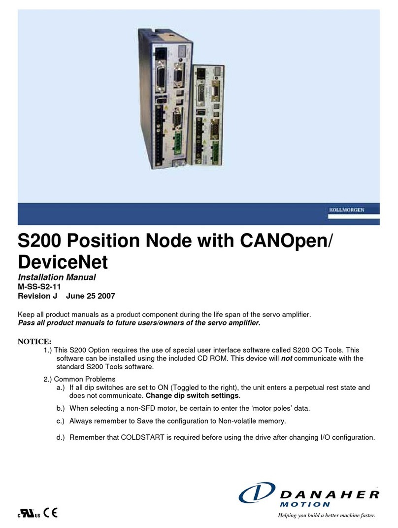
Danaher Motion SuperDrive ACS24 Series User manual

A
C SuperDrive
The AC motor controlle
r
Generation 5
User's Guide 1.0
Item No. 89Y05120A
26.04.2005
Solution b
y

Introduction 26.04.2005
Version History
Revision Edition date Reason for revision
Trademark information here
Product was developed under one or more US patents
Printed in Sweden. All rights reserved.
Danaher Motion is a registered trademark of Danaher Corporation. Danaher Motion makes every attempt to
ensure accuracy and ratability of the specification in this publication. Specifications are subject to change
without notice. Danaher motion provides this information “AS IS” and declines all warranties, express or
implied, including, but not limited to, implied warranties of mechanic ability and fitness for a particular purpose.
It is the responsibility of the product user to determine the suitability of this product for a specific application.
©2005 Danaher Motion
Item No. 89Y05120A User's Guide 1.0
2

26.04.2005 Introduction
Tables of contents
1Introduction ..................................................................................................................... 7
1.1 About AC SuperDrive documentation ..................................................................7
1.1.1 This version ....................................................................................................................................7
1.1.2 Copyright ........................................................................................................................................7
1.1.3 Scope .............................................................................................................................................7
1.1.4 Warning, caution and information notices ......................................................................................7
1.1.4.1 Product range.............................................................................................................................8
1.1.5 Related documents.........................................................................................................................8
1.2 About the AC SuperDrive.....................................................................................8
1.2.1 Personal safety...............................................................................................................................8
1.2.2 OEM's responsibility .......................................................................................................................8
1.2.3 Technical support ...........................................................................................................................8
1.2.4 Repair .............................................................................................................................................9
1.2.5 Product warranty ............................................................................................................................9
1.3 Product identification............................................................................................9
1.3.1 Configurations ................................................................................................................................9
1.3.2 AC SuperDrive identification label..................................................................................................9
1.4 Standard features and capabilities .....................................................................10
1.5 Available options ................................................................................................11
2Overview ....................................................................................................................... 13
2.1 Principles of operation........................................................................................14
2.1.1 Block diagram...............................................................................................................................14
2.1.2 CAN interface ...............................................................................................................................14
2.1.3 Speed control ...............................................................................................................................14
2.1.4 Flux control ...................................................................................................................................15
2.1.5 Slip and stator frequency estimation ............................................................................................15
2.1.6 Current control and SPWM-sym...................................................................................................15
2.1.7 Power conversion section ............................................................................................................15
2.1.8 Speed sensor interface ................................................................................................................17
2.1.9 Logic power ..................................................................................................................................17
2.2 Safety and protective functions ..........................................................................17
2.2.1 General.........................................................................................................................................17
2.2.2 Errors............................................................................................................................................17
2.2.3 Warnings ......................................................................................................................................18
2.3 Truck controller - AC SuperDrive communications.............................................18
2.3.1 General.........................................................................................................................................18
2.3.2 Node identification........................................................................................................................18
3Installation..................................................................................................................... 19
3.1 Introduction ........................................................................................................19
3.2 Cooling requirements .........................................................................................20
3.2.1 AC SuperDrive with finned heatsink.............................................................................................20
3.2.2 AC SuperDrive with flat heatsink..................................................................................................20
3.3 Clearances for access and air circulation...........................................................20
3.3.1 AC SuperDrive with finned heatsink.............................................................................................20
3.3.2 AC SuperDrive with flat heatsink..................................................................................................20
3.4 Orientation .........................................................................................................20
3.5 Mounting AC SuperDrive with fins heatsink .......................................................21
3.5.1 Dimensions and clearances .........................................................................................................21
User's Guide 1.0 Item No. 89Y05120A 3

Introduction 26.04.2005
3.5.2 Tools and equipment required...................................................................................................... 21
3.5.3 Procedure ..................................................................................................................................... 21
3.6 Mounting AC SuperDrive with flat heatsink ........................................................22
3.6.1 Dimensions and clearances ......................................................................................................... 22
3.6.2 Tools and equipment required...................................................................................................... 22
3.6.3 Procedure ..................................................................................................................................... 22
3.7 Wiring .................................................................................................................23
3.7.1 Motor and battery connections ..................................................................................................... 23
3.7.2 Making connections to terminal posts .......................................................................................... 24
3.7.3 Equipment required ...................................................................................................................... 25
3.8 On-board fuse sizing and selection ....................................................................25
3.8.1 Key start fuse F2 .......................................................................................................................... 26
3.8.2 Installation of on-board fuses ....................................................................................................... 26
3.9 Inrush current limiting resistance........................................................................27
3.10 Main contactor....................................................................................................27
3.11 Emergency stop switch.......................................................................................28
3.12 Key start input ....................................................................................................28
3.13 Control and I/O connections ...............................................................................28
3.13.1 General......................................................................................................................................... 28
3.13.2 120 ohm termination..................................................................................................................... 29
3.13.3 Speed encoder signals................................................................................................................. 29
3.13.4 ACS ID1 and ID2 inputs ............................................................................................................... 30
3.13.5 Temperature sensor ..................................................................................................................... 31
3.14 Can bus communications ...................................................................................32
4Start up & commissioning.............................................................................................. 35
4.1 General...............................................................................................................35
4.2 Checks prior to initial power up ..........................................................................35
4.3 Verifying AC SuperDrive readiness for operation ...............................................36
4.4 Configuring the AC SuperDrive for the application .............................................36
4.5 Operational checks in vehicle.............................................................................37
5Maintenance..................................................................................................................39
5.1 Periodic preventive maintenance .......................................................................39
5.1.1 AC SuperDrive with finned heatsink.............................................................................................39
5.1.2 AC SuperDrive flat heatsink ......................................................................................................... 40
5.2 Replacement of AC SuperDrive .........................................................................40
5.2.1 Drive removal ............................................................................................................................... 40
5.2.2 Drive Installation........................................................................................................................... 40
6Configuration & control of the AC SuperDrive ...............................................................41
6.1 Introduction.........................................................................................................41
6.2 CANopen and application control .......................................................................42
6.3 Speed measurement ..........................................................................................45
6.3.1 Tuning of speed measurement.....................................................................................................45
6.4 Speed control .....................................................................................................46
6.4.1 Speed ramp .................................................................................................................................. 47
6.4.1.1 General .................................................................................................................................... 47
6.4.1.2 Basics....................................................................................................................................... 48
6.4.1.3 Slopes ...................................................................................................................................... 49
6.4.1.4 Rollback ................................................................................................................................... 50
6.4.1.5 No ramp ................................................................................................................................... 50
Item No. 89Y05120A User's Guide 1.0
4

26.04.2005 Introduction
6.4.1.6 PDO controlled ramp................................................................................................................50
6.4.1.7 Parameter controlled ramp ......................................................................................................51
6.5 Best performance curve Option .............................................................................53
6.5.1.1 General ....................................................................................................................................53
6.5.2 Speed PI controller.......................................................................................................................53
6.6 Torque current limitation ....................................................................................53
6.6.1 Tuning of speed control................................................................................................................54
6.6.1.1 Tuning in parameter or PDO controlled ramp mode................................................................ 54
6.6.1.2 Tuning in no ramp mode ..........................................................................................................55
6.7 Flux control ........................................................................................................56
6.7.1 Basics ...........................................................................................................................................56
6.8 Parameters ........................................................................................................57
6.8.1 Tuning Of flux control ...................................................................................................................58
6.9 Slip and stator frequency estimation ..................................................................58
6.9.1 Parameters and variables ............................................................................................................58
6.9.2 Tuning of the slip and stator frequency estimation....................................................................... 59
6.10 Current control ...................................................................................................59
6.10.1 Basics ...........................................................................................................................................59
6.10.2 Parameters and variables ............................................................................................................60
6.11 Tuning of current control ....................................................................................61
6.12 SPWM-sym ........................................................................................................62
6.12.1 Basics ...........................................................................................................................................62
6.13 Open drain output control...................................................................................64
6.13.1 Parameters ...................................................................................................................................65
6.14 How the AC SuperDrive handles parameters ....................................................66
6.14.1 General.........................................................................................................................................66
6.14.2 Parameter verification at startup ..................................................................................................66
6.14.3 Saving parameters .......................................................................................................................67
6.14.4 Duplicating a configuration ...........................................................................................................67
6.14.5 Reverting to default parameters ................................................................................................... 68
7Troubleshooting guide................................................................................................... 69
7.1 General ..............................................................................................................69
7.2 Documentation for OEMs...................................................................................69
7.3 Errors .................................................................................................................69
7.4 Warnings............................................................................................................69
7.5 Status indicator ..................................................................................................70
7.6 Using the troubleshooting guide.........................................................................70
7.7 Troubleshooting chart ........................................................................................72
7.7.1 Main contactor doesn’t close........................................................................................................73
7.7.2 Fuse to power stage is blown.......................................................................................................74
7.7.3 AC SuperDrive status indicator is flashing or off.......................................................................... 75
7.7.4 Motor runs only at low speed .......................................................................................................76
7.7.5 Speed feedback sensor not connected........................................................................................77
7.7.6 Motor temperature error ...............................................................................................................78
7.7.7 Heatsink over temperature error ..................................................................................................80
7.7.8 AC current over current ................................................................................................................83
7.7.9 DC Bus high - hardware detected ................................................................................................84
7.7.10 DC Bus Low..................................................................................................................................85
7.7.11 CAN –time out ..............................................................................................................................86
7.7.12 Heatsink temperature sensor 1,2 – open circuit/short circuit ....................................................... 87
7.7.13 Motor - temp < -50 °C...................................................................................................................88
User's Guide 1.0 Item No. 89Y05120A 5

Introduction 26.04.2005
7.7.14 Motor temperature sensor open circuit/short circuit ..................................................................... 89
7.7.15 15 V supply low voltage................................................................................................................ 90
7.7.16 Reverted to default parameters.................................................................................................... 91
8AC SuperDrive specifications ........................................................................................ 93
8.1 General...............................................................................................................93
8.2 Current and power output ratings .......................................................................93
8.3 DC supply voltage requirement ..........................................................................94
8.4 Isolation ..............................................................................................................94
8.5 CAN communications interface ..........................................................................94
8.6 Safety system.....................................................................................................94
8.7 Operating environment.......................................................................................94
8.8 EMC ...................................................................................................................95
8.9 Safety and testing standards compliance...........................................................95
8.10 Mechanical tests.................................................................................................95
8.11 Physical characteristics ......................................................................................95
8.11.1 Weight .......................................................................................................................................... 95
8.11.2 Dimensions................................................................................................................................... 96
8.11.3 Surface requirements ................................................................................................................... 96
Item No. 89Y05120A User's Guide 1.0
6

26.04.2005 Introduction
1 INTRODUCTION
1.1 ABOUT AC SUPERDRIVE DOCUMENTATION
1.1.1 THIS VERSION
This version replaces all previous versions of this document. Danaher Motion Stockholm AB has
made every effort to insure this document is complete and accurate at the time of printing. In
accordance with our policy of continuing product improvement, all data in this document is
subject to change or correction without prior notice.
1.1.2 COPYRIGHT
This manual is copyrighted 2005 by Danaher Motion Stockholm AB. All rights reserved. This
manual may not be copied in whole or in part, nor transferred to any other media or language,
without the express written permission of Danaher Motion Stockholm AB.
1.1.3 SCOPE
This manual presents instructions, guidelines, diagram and other information relevant for
installation and maintaining the AC SuperDrive in an electrically powered vehicle utilizing the
CAN Bus and CANopen protocol for communications and control.
1.1.4 WARNING, CAUTION AND INFORMATION NOTICES
Special attention must be paid to the information presented in warning, caution and information
notices when they appear in this manual. Examples of caution, warning and information notices
along with an explanation of their purposes follow.
WARNING
♦ A Warning informs the user of a hazard or potential hazard that could
result in serious of fatal injury if the precautions or instructions given in
the warning notice are not observed.
CAUTION
♦ A Caution informs the user of a hazard or potential hazard that could
result in injury or damage to the equipment if the precautions or
instructions given in the caution notice are not observed.
i An Information Box contains supplemental information or references to
supplemental information on a topic.
Stop Box highlights important conceptual or procedural details that
must be understood and applied in order to successfully use the
product.
User's Guide 1.0 Item No. 89Y05120A 7

Introduction 26.04.2005
1.1.4.1PRODUCT RANGE
This manual presents important information about the AC SuperDrive Product Generation (5)
five.
1.1.5 RELATED DOCUMENTS
Object Dictionary (document number 89Y05110A). The Object Dictionary provides important
information about CANopen communication with the AC SuperDrive.
1.2 ABOUT THE AC SUPERDRIVE
1.2.1 PERSONAL SAFETY
Danaher Motion Stockholm AB provides this and other manuals to assist manufacturers in using
the AC SuperDrive in a correct, efficient and safe manner. Manufacturers must insure that all
persons responsible for the design and use of equipment employing the AC SuperDrive have the
proper professional skill and apparatus knowledge.
WARNING
♦ The high power levels and high torque available from a motor,
AC SuperDrive combination can cause severe or fatal injury.
CAUTION
♦ The AC SuperDrive is intended for connection only to DC battery
power sources and for use with low voltage asynchronous motors.
♦ Always verify before installation that the AC SuperDrive model is
correct for the vehicle’s battery supply voltage. The DC Supply
nominal voltage is stated on a label on the cover of each AC
SuperDrive.
1.2.2 OEM'S RESPONSIBILITY
The Danaher Motion AC SuperDrive products are intended for controlling motors in battery
powered electric vehicles. These drives are supplied to original equipment manufacturers
(OEMs) for incorporation into their vehicles and vehicle control systems.
OEM's are responsible for ensuring that AC SuperDrives are used for their intended purpose
only, safe function of the system and for compliance with all applicable regulations.
Responsibility for the safe functioning of the system reverts to the owner or user in all cases in
which a non-professional has done installation, service or repair and when the system is used for
other than its intended purpose.
1.2.3 TECHNICAL SUPPORT
For additional information on any topic covered in this document, or for additional information or
application assistance on any Danaher Motion Stockholm AB product, contact a Danaher Motion
Stockholm AB Application Center listed in the front of this manual.
Item No. 89Y05120A User's Guide 1.0
8

26.04.2005 Introduction
1.2.4 REPAIR
Repair and testing of the APS is available at Danaher Motion Stockholm AB.
The address is listed on page 99.
When returning defective unit in North America, contact Danaher Motion Stockholm AB in
Sewickley and obtain a RMA (Returned Materials Authorization) number prior to returning the
defective unit. Indicate the RMA number on the shipping container and paper work that
accompanies the returned unit.
1.2.5 PRODUCT WARRANTY
Refer to the sales agreement or contract under which the AC SuperDrive was purchased for a
complete statement of the product warranty.
1.3 PRODUCT IDENTIFICATION
1.3.1 CONFIGURATIONS
The AC SuperDrive is manufactured in the following two configurations:
• Convection cooled models (see Figure 1) employing a heat sink with cooling fins that transfer
heat to the surrounding air by convection.
• Conduction cooled models (see Figure 1) with a flat heat sink and mounting surface that
transfers heat into the surrounding vehicle structure by conduction.
1.3.2 AC SUPERDRIVE IDENTIFICATION LABEL
A label containing pertinent product identification information is affixed to the AC SuperDrive
cover next to the B+ terminal post. The product label fields relevant to product identification are
described below. For AC SuperDrive expressions, see Table 1. See Figure 1 for placement and
Figure 2 for a label appearance.
Figure 1. AC Superdrive with fins and flat Mounting Surface.
User's Guide 1.0 Item No. 89Y05120A 9

Introduction 26.04.2005
Figure 2. AC SuperDrive Product Identification Label.
Field Description
Danaher Motion Unique part number assigned to AC SuperDrives with a specific
hardware and software configuration. AC SuperDrives with the same
part number and revision are identical.
Rev. Indicates the revision level of the item.
Type
* Contact Danaher Motion Stockholm AB for further information.
Serie No. Production lot number (assigned by the factory). The production lot
number together with the sequence number yield a unique serial
number for each AC SuperDrive.
Serie No. Serial number within a production lot.
Manufacture date Year, month and day of manufacture.
Table 1. AC SuperDrive Product expressions.
1.4 STANDARD FEATURES AND CAPABILITIES
The AC SuperDrive incorporates a number of features and capabilities important to the electric
vehicle designer including:
• Modern AC flux-vector control techniques for improved performance and operating efficiency.
• A family of drives covering a wide range of power outputs and battery voltages.
• Programmable to match the characteristics of compatible induction motors.
• Designed for the environment of the electrically powered vehicle.
• Closed loop speed regulator provides unequalled vehicle speed control when moving and
neutral braking for maintaining position when stopped.
Item No. 89Y05120A User's Guide 1.0
10

26.04.2005 Introduction
• Full four-quadrant operation - drive can directly accelerate or decelerate the motor in both
forward and reverse directions (no direction contactors required).
• Recycles dynamic braking energy down to zero speed.
• Fully protected against undervoltage, overvoltage, overcurrent and reverse polarity and
overtemperature conditions.
• Built-in neutral start (also called high pedal) protection prevents vehicle motion on startup until
drive sees a zero speed command.
• CAN bus interface for safe and reliable networking in a truck control system.
• Total software configurability eliminates all operator adjustments and assures absolutely
reproducible performance of identically configured AC SuperDrives.
• All heat generating components mounted on a massive heatsink whose temperature is
monitored.
• Error/fault monitoring software implements necessary measures to prevent unsafe operation
of vehicle and motor/drive when problems exist.
• Warning/error codes and an error log provide informative and timely information for diagnosis
and elimination of problems.
• Total user control over acceleration, braking and speed.
1.5 AVAILABLE OPTIONS
The following are available options for the AC SuperDrive:
• BDI. (Battery Discharge Indicator)
• Programmable Best Performance Curve, see page 53.
User's Guide 1.0 Item No. 89Y05120A 11


26.04.2005 Overview
2 OVERVIEW
In a typical CAN based system (see Figure 3), one AC SuperDrive directs the motion of a lift
motor powering a hydraulic pump while a second AC SuperDrive directs the motion of a traction
motor coupled to a drive wheel. AC SuperDrives convert DC power from the truck’s battery to
three phase AC power at the frequencies and currents necessary to drive their respective
induction motors as commanded.
Figure 3. The Truck Drive System
The main contactor, under control of the truck controller, supplies battery power to the power
conversion section of the drives and removes battery power under certain error and fault
conditions. An onboard fuse protects each drive against short circuit faults in the power
conversion section.
A PTC (Positive Temperature Coefficient) resistance limits inrush current to a bank of filter
capacitors when power is first turned on via the disconnect switch.
The key start contactor controls application of power to the control electronics section of the AC
SuperDrive.
Each motor provides feedback of its speed, direction and temperature to the AC SuperDrive for
control and monitoring purposes. A speed encoder integrated into each motor produces speed
and direction feedback signals and a temperature sensor (PTC resistance) embedded in the
stator winding provides an indication of motor temperature.
The truck controller, based on input from operator controls and other criteria, transmits speed,
braking and other commands to the AC SuperDrives over the CAN Bus. The truck controller
regularly monitors drive status and initiates corrective action upon recognition of a warning/error
User's Guide 1.0 Item No. 89Y05120A 13

Overview 26.04.2005
condition. When a fault/error condition warrants, the truck controller may open the main
contactor, removing battery power from the AC SuperDrive power stage.
2.1 PRINCIPLES OF OPERATION
2.1.1 BLOCK DIAGRAM
Figure 4 shows a functional block diagram of the AC SuperDrive including the principal drive
inputs and outputs. Some SuperDrive functions are executed by dedicated hardware, while
others are implemented mainly in software. The following paragraphs provide additional details
on each functional block.
Figure 4. AC SuperDrive Block Diagram
2.1.2 CAN INTERFACE
The CAN Interface manages communications between the AC SuperDrive and the CAN Bus.
The CAN controller provides the electrical interface and within the software the CANopen
protocol is handled.
2.1.3 SPEED CONTROL
The Speed Control accepts speed set points (Command Speed) as input and produces torque
commands (Torque Current) as output. It can function as a closed loop, proportional or
proportional plus integral, speed controller with feedback provided by the speed encoder. It
includes provisions for limiting torque both in amplitude and derivate. It is also possible to use
Item No. 89Y05120A User's Guide 1.0
14

26.04.2005 Overview
advanced speed ramping functionality within the Speed Control block. The Speed Control is
implemented in software, with operating characteristics set by programmable parameters.
2.1.4 FLUX CONTROL
The motor flux is controlled within the Flux Control. The Magnetization Current, which produces
the motor flux, and the Slip Gain, which is reciprocally proportional to the Magnetization Current,
is the outputs from the Flux Control. Since the motor flux depends on the motor speed, the
measured motor speed is used to determine the optimal magnetization flux level.
2.1.5 SLIP AND STATOR FREQUENCY ESTIMATION
The Slip Speed and the Stator Frequency is estimated in the Slip and Stator Frequency
Estimation. The Slip Speed is computed from the Slip Gain and the Torque Current. The Stator
Frequency that is integrated in the Current Control to get the position of the dq-plane is computed
as the sum of the Actual Speed (electrical) and the Slip Speed.
2.1.6 CURRENT CONTROL AND SPWM-SYM
The dq-plane implemented current controller (so called vector control) controls the magnetization
current and the torque producing current independently of each other. The software implemented
Current Control is able to compensate for temperature and frequency related changes in motor
winding impedance as well as variations in the DC-supply voltage, thereby providing precise
control of motor flux and torque over a wide range of operating conditions. The Current Control
computes the required motor voltage, which is then realized by SPWM-sym (Sinusoidal Pulse
Width Modulation with symmetrisation). The output from the SPWM-sym block is the MOSFET
gate pulses.
2.1.7 POWER CONVERSION SECTION
The principal drive output, a variable frequency, variable amplitude, three phase current, is
produced by the Power Conversion section from a DC power source. Figure 5 shows the general
circuit configuration. Depending on its current rating, a SuperDrive may employ more or less
transistors than illustrated in Figure 5. During braking, regenerated energy from the motor is
returned to the battery.
All power components are mounted and thermally bonded to a large heatsink that forms one
surface of the drive. Heatsink temperature and DC supply voltage are sensed and monitored for
control and protection purposes.
Utilizing efficient MOSFET power transistors, the Power Conversion section amplifies three PWM
(Pulse Width Modulated) current commands supplied by the Current Regulator producing three
PWM voltages (see Figure 6). These PWM voltage waveforms, when applied to the inductance
of the stator, produce currents in the motor, which approximate sine waves.
User's Guide 1.0 Item No. 89Y05120A 15

Overview 26.04.2005
pwm (u)
pwm (v)
pwm (w)
pwm (u)
pwm (v)
pwm (w)
+
B-
UVW
isens(u)
isens(v)
heat sink
temp sens
UPPER
LOWER
G0028.CDR
Figure 5. Power Conversion Section.
Figure 6. Pulse Width Modulation.
During braking, the rotor runs at higher speed than the speed of the synchronous flux vector and
the motor functions as a generator, supplying power to the battery. The change from motor to
generator is smooth and instant when rotor speed exceeds synchronous speed. The AC
SuperDrive supplies a magnetizing current at the proper frequency for optimum regeneration
performance. The generated power is dependent on the slip (which the AC SuperDrive controls).
The transistors functions as a 6-pulse rectifier (see Figure 7), converting the 3-phase AC current
to DC-current that charges the battery.
Item No. 89Y05120A User's Guide 1.0
16

26.04.2005 Overview
Figure 7. Current Flow During Regeneration.
2.1.8 SPEED SENSOR INTERFACE
The Speed Sensor Interface converts the quadrature pulse outputs from a speed encoder to
digital speed and direction numbers for use by other drive and system functions.
2.1.9 LOGIC POWER
The Logic Power Supply converts battery voltage applied via the KEY START input to the voltages
required internally.
2.2 SAFETY AND PROTECTIVE FUNCTIONS
2.2.1 GENERAL
The SuperDrive performs extensive checks and monitoring to protect the motor, drive and vehicle
from damage and prevent operation under unsafe conditions. Two response levels are
employed: warning level and error level. Errors are serious problems that prohibit continued
operation of the AC SuperDrive. Less serious problems that permit continued AC SuperDrive
operation, often at reduced capacity, produce warnings.
For some items monitored, the AC SuperDrive provides a two stage response including a
warning when the item is approaching it’s safe operating limit and an error response when the
safe operating limit is exceeded.
i A complete Troubleshooting guide for the AC SuperDrive is presented at
page 69.
2.2.2 ERRORS
When an error is detected, the AC SuperDrive operating software immediately stops motion then
shuts down the drive’s power output to the motor. Concurrently, the AC SuperDrive’s internal
error status is updated to reflect the error code(s) for existing error conditions and an emergency
message containing the new error status is sent. The AC SuperDrive’s status indicator changes
from steady on to flashing.
User's Guide 1.0 Item No. 89Y05120A 17

Overview 26.04.2005
i An inherent safety feature of the AC SuperDrive is that no single component
failure can cause a run away condition in the controlled motor. Since DC current
produces no torque in an induction motor, a shorted output transistor in the
Power Conversion section causes the motor to slow down or stop.
2.2.3 WARNINGS
The AC SuperDrive’s internal warning status is updated to reflect the code(s) for existing warning
conditions. Operating with active warning conditions does not affect the AC SuperDrive’s status
indicator, which remains in steady on condition. When the root cause of a warning is removed,
the AC SuperDrive automatically removes any reduced capacity restriction related to the warning
condition.
2.3 TRUCK CONTROLLER - AC SUPERDRIVE
COMMUNICATIONS
2.3.1 GENERAL
On a truck CAN network the truck controller functions as the master and AC SuperDrives are
slaves. Commands, motion variables and parameters exchanged between a truck controller and
an AC SuperDrive are embedded in CANopen communication objects. In the CANopen
Communications protocol implemented in the ACS, the following five types of objects (messages)
are utilized:
OBJECT (MESSAGE) TYPE PURPOSE
SERVICE DATA OBJECT (SDO) Exchange of non-real time data and control.
PROCESS DATA OBJECT (PDO) Exchange of real time data and control.
SYNCHRONISATION OBJECT (SYNC) Broadcast periodically by the master to all slaves to
synchronize network devices and processes with the master.
NETWORK MANAGEMENT(NMT) Transmitted by the master to control network boot up,
initialization and state transitions. Network management
messages may be directed to individual devices or broadcast
to all network nodes.
EMERGENCY (EMCY) Transmitted by slaves to signal internal error conditions to the
master.
The AC SuperDrives may be configured to utilize the periodic SYNC message from the truck
controller (or other device on the CAN Bus) by which the SuperDrive confirms that the truck
controller and CAN communications are functional. Upon reception of the SYNC object, the AC
SuperDrive initiates the sending of a Transmit PDO containing a summary of its operating state.
The AC SuperDrive can also be configured so that the Transmit PDO is initiated by the periodic
Receive PDO. Then there is no need of a periodic SYNC object.
Each AC SuperDrive requires a periodic Receive PDO containing motion and related control
variables. The AC SuperDrive can be configured to use one or two Transmit/Receive PDOs.
2.3.2 NODE IDENTIFICATION
Messages intended for specific devices on the CAN network contain a COB-ID (Communications
Object - Identifier) field which identifies the target node (device) for the message. Each AC
SuperDrive on the CAN Bus determines its COB-ID via the wiring configuration on two contacts
of the interface (connector K1) mating connector. Each AC SuperDrive on the Bus must have a
unique ID.
Item No. 89Y05120A User's Guide 1.0
18

26.04.2005 Installation
3 INSTALLATION
3.1 INTRODUCTION
This chapter presents instructions and guidelines for installing an AC SuperDrive in a vehicle.
The information is general in nature. The actual procedure for mounting the AC SuperDrive in a
specific vehicle may vary from what is presented here or include additional steps.
i Mounting brackets, rails and attaching hardware are not supplied with
the AC SuperDrive. These items must be ordered separately.
i The bolt length is depending on thickness at the mounting brackets.
The mounting brackets are not supplied by Danaher Motion
Stockholm AB
Figure 8. Calculate bolt length for mounting finned heatsink.
We offer the following guidelines and precautions regarding mounting location for the AC
SuperDrive:
• AC SuperDrive’s cover provides a measure of protection from liquids and particles dripping,
splashing or spraying onto the unit; however, the AC SuperDrive is not environmentally
sealed. It should not be located in a place where it is subjected to liquids under high
pressure.
• The protection class, IP54, is only valid when the mating connector, K1, is inserted.
• The cooling fins on the bottom surface of the AC SuperDrive must remain relatively clean in
order to effectively cool the unit. Avoid locating the AC SuperDrive where it may be subjected
to high concentrations of dust, oil etc. which may accumulate on the cooling fins.
• The AC SuperDrive LED status indicator provides useful diagnostic information for
troubleshooting of some vehicle problems. The troubleshooting process can be facilitated if
this indicator is visible.
• Consideration should be given to accessibility of the on-board fuse.
• High power levels are available at each of the connection posts. Therefore they should be
protected from accidental short circuits.
User's Guide 1.0 Item No. 89Y05120A 19

Installation 26.04.2005
3.2 COOLING REQUIREMENTS
3.2.1 AC SUPERDRIVE WITH FINNED HEATSINK
A massive heatsink comprising the entire bottom surface of the AC SuperDrive transfers heat
from the Power Conversion section components into the surrounding air. Drives operating at or
near their continuous power output (1 hour rating) require forced air cooling to maintain heat sink
temperature in the safe operating zone.
We recommend ambient temperature air at Operating environment at page 94 be directed over
the heatsink fins to maintain heatsink temperature below 85 °C. Either an axial blower or two
small muffin fans can provide the necessary airflow for two AC SuperDrives.
In typical applications, the truck controller monitors heatsink temperature and regulates either fan
speed or on/off cycle to maintain heatsink temperature below 85 °C.
3.2.2 AC SUPERDRIVE WITH FLAT HEATSINK
A massive heatsink comprising the entire bottom surface of the AC SuperDrive transfers heat
from the Power Conversion section components into the body of the vehicle. Drives operating at
or near their continuous power output (1 hour rating) require different thermal resistance
depending on ACS size for dissipation of heat to maintain heat sink temperature in the safe
operating zone. For thermal resistance see Operating environment at page 94.
3.3 CLEARANCES FOR ACCESS AND AIR CIRCULATION
For all AC SuperDrive models 50 mm clearances in front of and behind the AC SuperDrive are
required for airflow. 50 mm clearance above the AC SuperDrive is required for
installation/removal of interface connectors and wiring. Refer to Figure 37 for dimensions for all
AC SuperDrive.
3.3.1 AC SUPERDRIVE WITH FINNED HEATSINK
The AC SuperDrive is cooled by the airflow over the finned heatsink that forms its bottom
surface. Clearance above and below the drive and between the heatsink and vehicle are required
for air circulation. In some applications forced air-cooling is required (see Operating
environment).
3.3.2 AC SUPERDRIVE WITH FLAT HEATSINK
The AC SuperDrive is cooled by the surface contact to the vehicle body. Observe demands to
surface roughness and surface flatness where the AC SuperDrive is mounted to the vehicle
body. Apply thermal grease (Amount, see page 21) at the AC SuperDrive before mounting for
best cooling effect.
3.4 ORIENTATION
The AC SuperDrive is not to be orientated upsidedown; either horizontal or vertical mounting is
acceptable, although a horizontally mounted unit tolerates higher levels of mechanical shock than
a vertically mounted unit. When mounted vertically, the AC SuperDrive should be oriented with its
cooling fins aligned vertically. Consideration should be given to accessibility of the on-board fuse
and visibility of the on-board status indicator for maintenance purposes. High power levels are
Item No. 89Y05120A User's Guide 1.0
20
This manual suits for next models
3
Table of contents
Other Danaher Motion Controllers manuals
Popular Controllers manuals by other brands

Smarteh
Smarteh LPC-2.ID2V user manual

Tech Controllers
Tech Controllers EU-F-4z v2 user manual

Siemens
Siemens RWD45U Installation and commissioning guide

cashco
cashco HP Installation, operation & maintenance manual

Honeywell
Honeywell M896 installation instructions

Roku
Roku BrightSign HD110 quick start guide