Danaher Motion THOMSON Electrak 10 Series User manual

Electrak 10 Series / Electromechanical Linear Actuator
www.danahermotion.com Installation & Operation Manual

INTRODUCTION
Danaher has many years of experience designing and manufacturing linear actuators for a wide variety of applica-
tions on combines, school buses, industrial sweepers, vans for the handicapped, and other mobile applications.
The Danaher linear actuator you have purchased is a well designed, high quality unit which will provide consistent,
maintenance-free service throughout its life. When the Electrak 10 is mated with an MCS-2000 series control, it will
provide controlled linear force for applications which require moving, positioning, adjusting, or opening and closing
on in-plant or mobile applications.
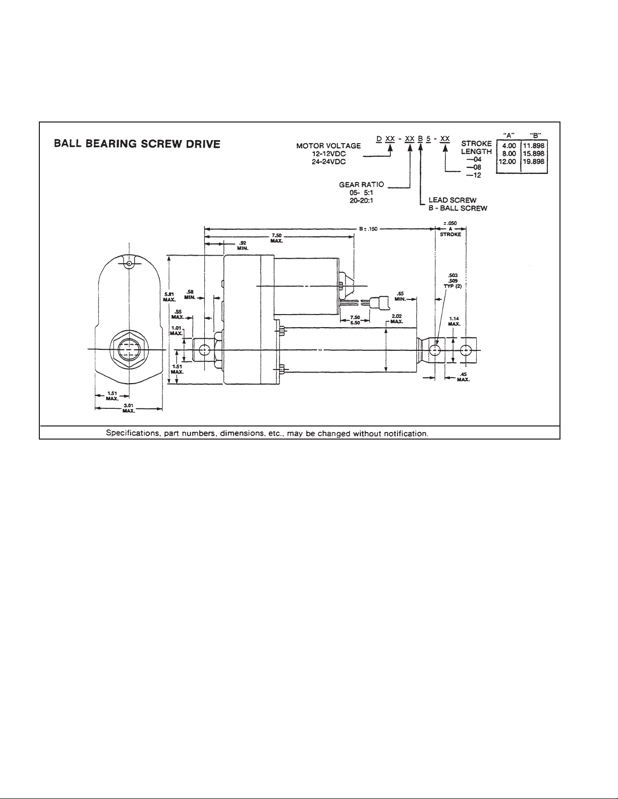
This manual provides complete information needed to install and troubleshoot Danaher D12-05B5, D12-20B5, D24-
05B5 and D24-20B5 DC linear actuators. All of these products are easy to apply and require no maintenance.
Please follow the instructions provided in this manual carefully to ensure safe, reliable operation. The Application
Notes found on page 3 are of paramount importance, so be sure to read them care thoroughly before proceeding with
installation. All stated or implied manufacturer’s warranties are voided if this product is not installed and operated in
accordance with these instructions.
Description Page
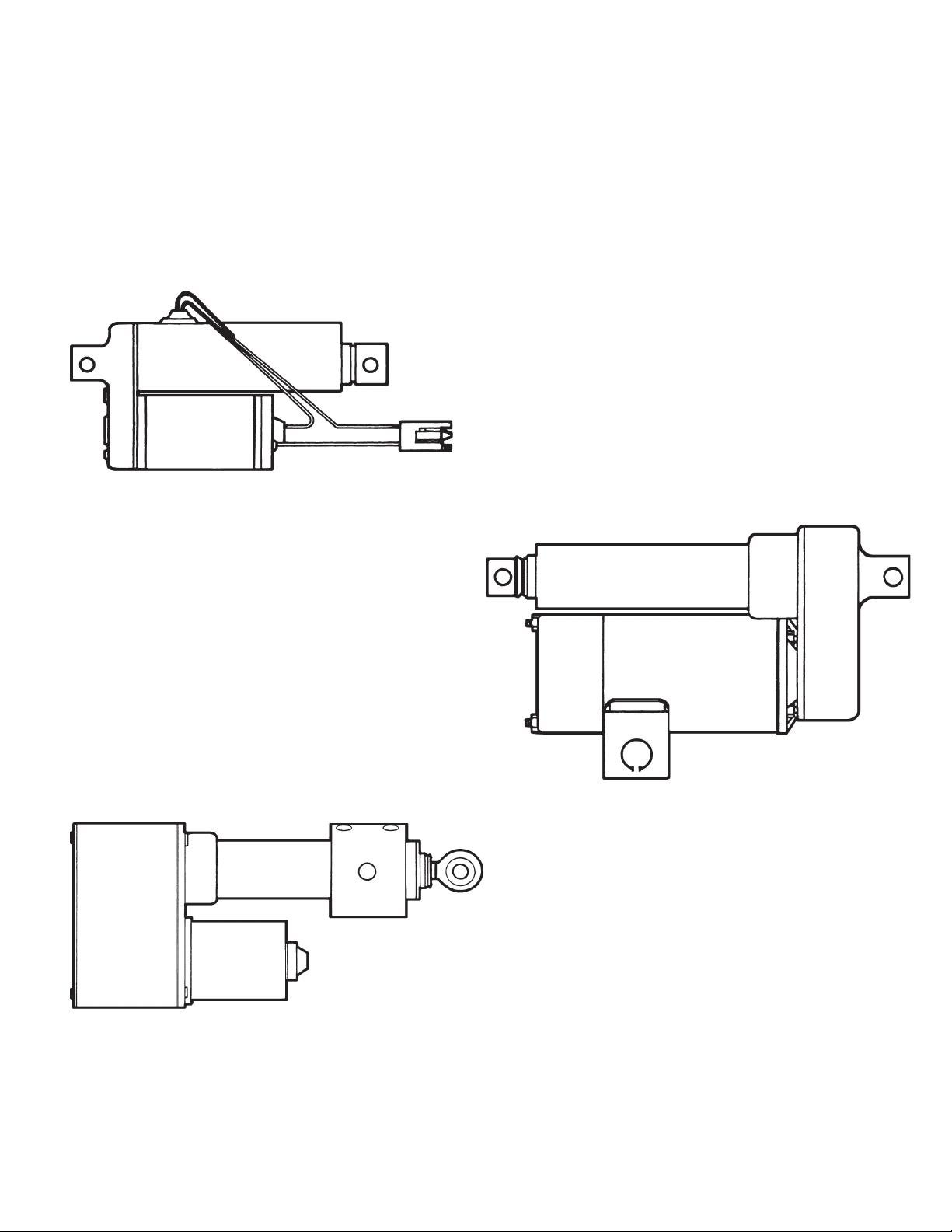
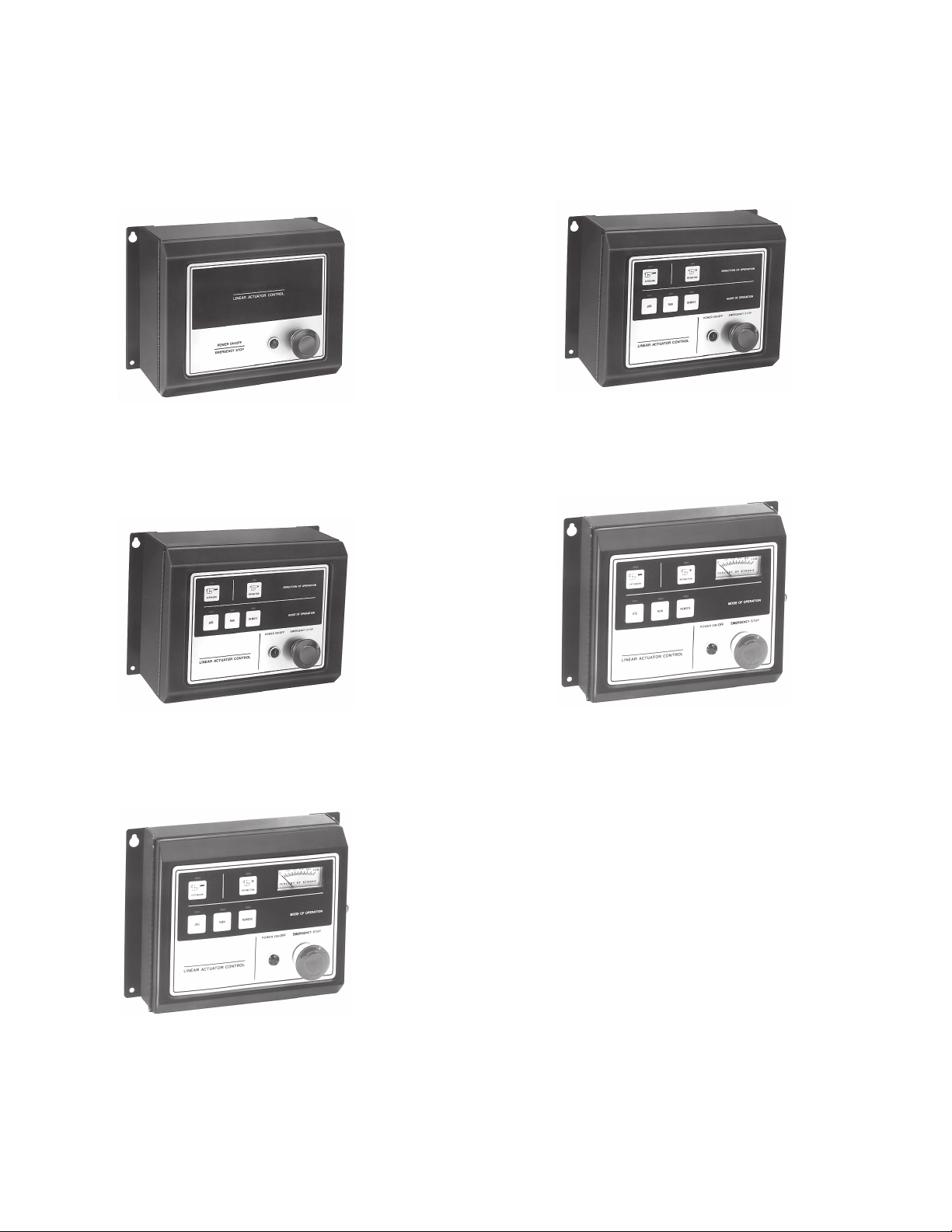
Other Actuator Products.......................................................................................... 1
Application Notes .................................................................................................... 3
Specifications .......................................................................................................... 3
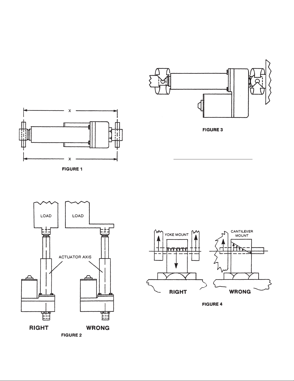
Mounting ................................................................................................................. 4
Electrical Installation ................................................................................................ 5
Troubleshooting ....................................................................................................... 7
Dimensions .............................................................................................................. 8
TABLE OF CONTENTS
WARRANTY
Danaher warrants that it will repair or replace (whichever it deems
advisable) any product manufactured and sold by it which proves
to be defective in material or workmanship within a period of one (1)
year from the date of original purchase for consumer, commercial
or industrial use.
This warranty extends only to the original purchaser and is not
transferable or assignable without Danaher’s prior consent.
Warranty service can be obtained in the U.S.A. by returning
any defective product, transportation charges prepaid, to the
appropriate Danaher factory. Additional warranty information may
be obtained by writing the Customer Service Department:
Danaher Motion
1300 N. State St.
Marengo, Il. 60152
Phone: 1-800-554-8466
A purchase receipt or other proof of original purchase will be
required before warranty service is rendered. If found defective
under the terms of this warranty, repair or replacement will be made,
without charge, together with a refund for transportation costs. If
found not to be defective, you will be notified and, without your
consent, the item will be repaired or replaced and returned to you
at your expense.
This warranty covers normal use and does not cover damage or
defect which results from alteration, accident, neglect, or improper
installation, operation, or maintenance. Some states do not allow
limitation on how long an implied warrant lasts, so the above
limitation may not apply to you.
Danaher’s obligation under this warranty is limited to the repair or
replacement of the defective product and in no event shall Danaher
be liable for consequential, indirect, or incidental damages of any
kind incurred by reason of the manufacturer, sale or use of any
defective product. Danaher neither assumes nor authorizes any
other person to give any other warranty or to assume any other
obligation or liability on its behalf.
WITH RESPECT TO CONSUMER USE OF THE PRODUCT, ANY
IMPLIED WARRANTIES WHICH THE CONSUMER MAY HAVE
ARE LIMITED IN DURATION TO ONE YEAR FROM THE DATE
OF ORIGINAL CONSUMER PURCHASE. WITH RESPECT TO
COMMERCIAL AND INDUSTRIAL USES OF THE PRODUCT, THE
FOREGOING WARRANTY IS IN LIEU OF AND EXCLUDES ALL
OTHER WARRANTIES, WHETHER EXPRESS OR IMPLIED BY
OPERATION OF LAW OR OTHERWISE, INCLUDING, BUT NOT
LIMITED TO, ANY IMPLIED WARRANTIES OF MERCHANTABILITY
OR FITNESS.
Some states do not allow the exclusion or limitation of incidental or
consequential damages, so the above limitation or exclusion may
not apply to you. This warranty gives you specific legal rights and
you may also have other rights which vary from state to state.

Danaher’s family of actuators offers the right load capacity,
stroke length, and control package for almost every
application. With stroke lengths from 2 to 24 inches, load
ratings from 25 to 1000 lbs., AC or DC models, and control
systems from simple on-off control to sophisticated
closed loop sensing types, Danaher actuator systems
Electrak 100 – Potentiometer position feedback control
and internal adjustable limit switches make this Danaher’s
most sophisticated actuator.
Load Ratings: 500 or 1000 lbs.
Power Input: 24 VDC
Stroke Lengths: 4, 8, 12, 18, or 24 inches
Feedback: 10K ohm potentiometer
Other Actuator Products
Electrak 1 – Nominal load capacities in a small
package.
Load Ratings: 25 or 75 lbs. max.
Stroke Lengths: 2, 4, or 6 inches
Power Input: 12 or 24 VDC
Overall Lengths: 7 to 11 inches, depending on stroke.
Electrak 5 – A 115 VAC for in-plant applications.
Load Ratings: 500 lbs. max.
Stroke Lengths: 4, 8, 12, 18 or 24 inches
1
encompass a broad product range. The actuator series
described on this page are available at your local Danaher
distributor or directly from the address on the back cover
of this manual.
Ask for catalog no. P-786 for more information on these
products.

The Danaher family of actuator controls - a choice of separate or combined power supplies and controls to meet
your various needs.
MCS-2015
A power supply for use with a remote control station,
photoscanner or programmable controller to run any 24
VDC actuator. 115/230 VAC input, 24 VDC output, thermal
overload protection, fused, power on/off switch.
MCS-2025
Combines the power supply of the MCS-2015 and the
control of the PC compatible MCS 2020 in a single
enclosure for ease of installation and wiring.
MCS-2020
A control that can be used with the MCS-2015 or other 12
or 24 VDC power sources. Provides extend, retract, jog,
run and auto return functions. Programmable controller
compatible, 12 or 24 VDC input-output.
MCS-2035
Combines the power supply of the MCS-2015 and the
control of the PC compatible MCS-2030 in one enclosure
for ease of installation and wiring.
MCS-2030
Same as the MCS-2020 but includes an analog meter to
display the position feedback from the Electrak 100.
2

3
Application Notes
I. Always make sure power is off before attempting to work on or near the actuator and its electrical controls.
2. Electrak 10 actuators are load protected with a slip clutch. The clutch will slip when the load exceeds the
actuator’s rating, preventing any movement of the load. The clutch is factory set based on load rating.
3. The duty cycle for the Electrak 10 actuator is 25% “on time”. For instance, an actuator operating for 25 seconds
must remain off for 75 seconds before operating again. Exceeding this maximum will cause the motor to overheat
and trip its internal thermal breaker.
4. Electrak 10 actuators are weather protected for use in outdoor applications, but they are not waterproof and
should not be used in underwater conditions
5. Electrak 10 actuators are not explosion or dust ignition proof; do not use in those types of environments.
6. Electrak 10 actuators are factory lubricated for life. No disassembly is ever required for routine maintenance
purposes.
Specifications
Stroke Length: 4, 8 or 12”
Duty Cycle: Twenty-five percent “on” time at 75° F at rated load (higher duty cycles at lower loads)
Life: 20,000 cycles, nominal
Motor Protection: Automatically reset thermal overload protection.
Temperature Range: -150F to +150° F
End Play: .070 inch maximum
Overload Protection: Mechanical load limit clutch
Mounting: Actuator ends must be restrained from rotating (to counter 90 in-lb maximum torque
developed) and mounted with parallel pins equally supported on both ends. Actuator
not to be mounted off of cover (outer) tube.
Lead Wires: 14 AWG PVC, 800C insulation
Static Loads: 3000 lbs. maximum
Dynamic Loads:

4
MOUNTING
Danaher linear actuators are quickly and easily mounted
by slipping pins through the holes on each end of the unit
and into brackets on the machine frame and the load.
Half inch diameter solid pins provide maximum holding
strength and a retaining or cotter pin on each end will
prevent the solid pin from falling out of its mounting
bracket. Roll or spring type mounting pins should be
avoided. The mounting pins must be parallel to each
other as shown in Figure 1. Pins which are not parallel to
each other may cause the actuator to bind.
The load should act along the stroke axis of the actuator
since off center loads may cause binding and lead to
premature failure. See Figure 2.
The actuator mounting brackets must be able to
withstand the torque which is developed when the unit
extends or retracts. Restraining torque required varies
with the model being used. See Figure 3 and the chart
below.
Make sure mounting pins are supported on both ends.
Cantilever mounts are unacceptable. Failure to do so
could shorten the life of the actuator.
NOTE: Do not attempt to mount the Electrak 10 on its cover tube. The tube is not designed to support the
forces required for this type of mounting.
Torque Required
Actuator In.-Lbs.
D12-05B5 60
D24-05B5 60
D12-20B5 90
D24-20B5 90

5
Wiring
Danaher linear actuators should be connected in
accordance with the diagram show below.
Make sure power is off before attempting to wire
actuator.
WIRE GAUGE SELECTION
DC Actuators
Long lead wires between the power source and the
actuator will result in a voltage drop for DC units.
This voltage drop can be avoided by sizing the wires
in accordance with the following wire gauge selection
chart, which is based on a 12 or 24 VDC power source.
In order to use the chart, find the point of intersection of
the two known factors, such as amperage and distance,
and read the required wire gauge from the curves on the
chart. Example: A D12-2OB5 actuator draws 14 amps
current at rated load. The intersection of the maximum
current and the distance between the actuator and
power source (44 feet, for example) indicates the wire
gauge required (#12).
SWITCHES
Actuator direction (forward, reverse) is controlled with a
double-throw switch with the center position 11 off.”
DC Actuator Switches
DC actuators require double pole, double throw
switches. McGill switch no. 0111-004, Cutler Hammer
switch no. 8835- or equivalent are recommended and
are usually available locally. The required switch can be
purchased locally or from Danaher under part number
830-8004-016. Here are the required parameters:
- Double-pole, double-throw
- 20 Amp at 28 VDC
- Lever seal to keep out dirt and moisture
- Center “off”
- Two momentary contacts
- 15/32” bushing
- Screw terminals
CONNECTORS
Packard Electric connector 56 Series No. 2984883 and
56 Series No. 29692987. Male blade provided on DC
actuators.
ACTUATION
To extend actuator, connect red to positive and yellow to
negative. To retract actuator, connect yellow to positive
and red to negative.
ELECTRICAL INSTALLATION

6
Danaher actuators may also be interfaced with the MCS-2000 Series controller.
Available controllers are as follows:
MCS-2015 Power Supply - 110 VAC in, 24 VDC out, 17 Amp maximum.
MCS-2020 Actuator Controller - Capable of extend and retract functions in a jog or continuous run
model. For use with 12 or 24 VDC actuators.
MCS-2025 Combined Controller and 24 VDC power supply. Performs same functions as MCS-2020.
WIRING EXTERNAL LIMIT SWITCHES
(OPTIONAL)

7
TROUBLESHOOTING
Covers D12 and D24 Models
General: The chart below will be helpful for isolating malfunctions in the control system, countering difficulties with
system start-up, and in troubleshooting for worn or broken mechanical or electrical components in units which have
been operating for sometime. For correct diagnosis it is important to do all tests before disassembling the actuator.
If the actuator is being used in conjunction with an MCS controller, see Troubleshooting Guide in controller manual
for additional checkpoints.
Symptom: Actuator will not extend/retract
Checkpoint Probable Cause Possible Solution
No voltage or amp draw Actuator not receiving power -Check power supply
Proper voltage, no amp draw Dead motor -Replace motor
Thermal overload cut-out -Let cool, check duty cycle
(when overheated)
Proper voltage, amp draw Actuator overloaded -Check rated load
present, clutch slips
Clutch worn too low -Replace clutch
(Excessive ratcheting)
Symptom: Actuator stops in mid-stroke
Checkpoint Probable Cause Possible Solution
Clutch slips Actuator overloaded -Check rated load
Clutch doesn’t slip, no amps Blown fuse (customer provided) -Replace fuse
Thermal cut-out -Let cool, check duty cycle
Clutch doesn’t slip, amps Motor stalled -Check voltage too low
present
If the above checks do not reveal the source of the difficulty, remove actuator from the mechanism to run by itself.
Watch and listen for any changes in behavior.

8
DIMENSIONS
The outline drawing shown below describes Electrak 10 ball bearing screw driven actuators.
The tabulated dimension chart shows these lengths for each model and also describes the part
numbers.


P-264-10 9/04 Printed in U.S.A.
Danaher Motion
1300 N. State St.
Marengo, Il. 60152
Phone: 1-800-554-8466
Fax: 1-800-445-0329
E-mail: [email protected]
Literature: litr[email protected]
Or write:
Danaher Motion
1300 N. State St.
Marengo, Il. 60152
This manual suits for next models
4
Table of contents
Other Danaher Motion Controllers manuals