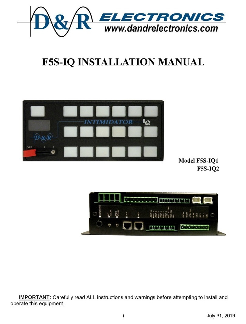
D&R ELECTRONICS F5M-IQ User manual

1 July 31, 2019
F5M-IQ INSTALLATION MANUAL
Model F5M-IQ1
F5M-IQ2
IMPORTANT: Carefully read ALL instructions and warnings before attempting to install and
operate this equipment.

2 July 31, 2019
TABLE OF CONTENTS
1—UNPACKING & PRE-INSTALLATION CHECK……………………………………. Page 3
2—SAFETY CONSIDERATIONS………………………………………………………... Page 3
3—SPECIFICATIONS……………………………………………………………………... Page 4
4—INSTALLATION………………………………………………………………………... Page 5
5—LABELING INSTRUCTIONS…………………………………………………………. Page 6
6—F5M-IQ DEFAULT CONFIGURATION……………………………………………… Page 7
7—F5M-IQ TOUCHPAD PROGRAMMING…………………………………………….. Page 8
8—F5M-IQ VOLTAGE CALIBRATION…………………………………………………. Page 8
9—F5M-IQ TEMPERATURE CALIBRATION………………………………………….. Page 9
10—F5M-IQ TOUCHPAD BACKLIGHT QUICK SETTING…………………………... Page 9
11—IMAGES……………………………………………………………………………….. Page 10
REAR VIEW CONNECTORS LAYOUT…………………………………………... Page 10
FRONT VIEW CONNECTORS LAYOUT…………………………………………. Page 11
TOP VIEW (FUSES AND LED INDICATORS)…………………………………... Page 11
12—TOUCHPAD SETUP FILE UPLOAD ERROR CODES………………………….. Page 11
13—WARRANTY & PRODUCT RETURN POLICY…………………………………… Page 12

3 July 31, 2019
1. Unpacking & Pre-Installation Check
D&R Electronics Co. recommends that you open and examine all shipments within 48 hours of receipt.
The INTIMIDATOR IQ systems are shipped pre-assembled and factory tested. All necessary hardware for
standard installation is included. Use this pre-installation check list to verify your unit:
1.Confirm contents with the packing slip
2.Examine unit for damaged in transit (i.e. scratches, broken or bent connectors. etc.).
If any damage has occurred, file a claim IMMEDIATELY with the courier stating the extent of damage.
Check ALL envelopes, packing slips, shipping labels and tags before removing or destroying them.
2. Safety Considerations
The effectiveness of this system is highly dependent upon its proper installation. Please read and follow ALL
instructions provided in this manual before attempting the installation.
For proper installation of this product you must have a good understanding of automotive electrical systems
and procedures, as well as proficiency in installation and servicing of emergency vehicle sound, lighting
and warning equipment. We recommend this equipment be installed only by qualified personnel.
•DO NOT connect this system to vehicle battery until all other electrical connections have been complet-
ed, and have been checked that no short-circuits exist.
•When passing wire through compartment walls and drilling holes is required, the installer MUST check
both sides of the drilling surface before drilling. Make sure that no vehicle components could be dam-
aged by the drilling operation. Clean the holes and remove any burrs. Use a grommet of appropriate size
and sealants when passing the wires through the compartment walls.
•Looms, grommets, cable ties or other installation hardware should be used to anchor and protect wires.
•Splices should be minimized and made in a fashion so as to protect them from corrosion to minimize the
possibility of loss of conductivity over time.
•INSTALLATION OF ALL EQUIPMENT AND WIRING SHALL NOT OBSRUCT, IMPEDE OR INTER-
FERE WITH THE DEPLOYMENT OF VEHICLE AIR BAGS, OTHERWISE IT COULD POSSIBLY RE-
DUCE THE EFFECTIVENESS THE AIR BAG SYSTEM CAUSING SERIOUS INJURY (OR EVEN
DEATH) IN THE EVENT OF AN ACCIDENT.
•If using non-D&R Electronics components, such as speaker(s), be sure that they are properly rated for
the system you are installing.
•All speakers should be installed in a location that will produce minimum sound levels inside the vehicle,
while maximizing the warning signal effectiveness to oncoming traffic on the exterior of the vehicle.
•This device is intended for use by authorized personnel only. The user responsibility is to ensure that all
local, state/provincial and federal laws are being complied with. D&R assumes no liability for any loss
resulting from the use of this device.
WARNING!
The D&R Electronics INTIMIDATOR siren/light controller is an advanced microprocessor based system. Un-
like conventional systems, malfunctions and/or improper operation will result if proper installation procedures
are not followed. Refer to any accompanying diagrams and pay particular attention to WARNINGS, CAU-
TIONS and HAZARDS listed in this document. Follow instructions exactly as shown where so indicated.
HEARING HAZARDS!
Your hearing and that of others, in or near the emergency vehicle could be affected by the very loud emer-
gency sounds generated. Hearing loss or damage could result due to short-term exposure to excessively
loud sounds! Each jurisdiction (country, province/state, etc.) has specific regulations governing ex-
posure to sound. During installation and testing it is recommended that anyone working in the vicinity of the
vehicle to wear approved hearing protection devices.

4 July 31, 2019
3. Specifications
General
Input Voltage ..........................................................11 to 16 Volts DC
Input Fuse ..............................................................60 Amps (external)
Operating Temperature Ranges ..............................-40oC to +65oC
Standby Current ......................................................50mA + 10% during IGNITION OFF time-out
….………………………..………….ØmA after time-out
Control Box Weight Control Box Physical Dimensions
Height .................................2 - 1/16” (68mm)
Single Siren………………..5.34lb / 2.42kg Width ..................................6 - 3/8” (161mm)
Dual Siren………………….7.12lb / 3.23kg Length ................................8 - 5/8” (218mm)
Siren
Operating Current ..................................................10 Amps—Single Amplifier
Frequency Range ..................................................700 to 1640 Hz (nominal)
Cycle Rate
Wail ............................................................20 cycles/min
Yelp ............................................................200 cycles/min
Stinger ........................................................800 cycles/min
Nominal Voltage Output .........................................52V p-p (11Ω load)
Audio Frequency Response ..................................100 – 4000 Hz + 3dB
Audio Distortion .....................................................10% or less
Audio Output Power ...............................................32 watts
Siren Output Power………………………………....100 Watts
NOTE: TOTAL current draw not to exceed 60A including siren
Current Outputs
PLUG 1
Pin 4……………….OUTPUT #1…… 20 Amp Max. (fused 20A)
PLUG 2
Pin 2……………….OUTPUT #1…….10 Amp Max. (fused 15A)
Pin 3………………..OUTPUT #2………………...10 Amp Max. (fused)
Pin 4………………..OUTPUT #3………………...10 Amp Max. (fused)
Pin 5………………..OUTPUT #4………………...10 Amp Max. (fused)
Pin 6………………..OUTPUT #5………………...10 Amp Max. (fused)
Pin 7………………..OUTPUT #6………………...10 Amp Max. (fused)
Pin 8………………..OUTPUT #7………………...10 Amp Max. (fused)
Pin 9………………..OUTPUT #8………………...10 Amp Max. (fused)
PLUG 3
Pin 1………………..OUTPUT #9………………...2 Amp Max.
Pin 2………………..OUTPUT #10……………….2 Amp Max.
Pin 3………………..OUTPUT #11……………….2 Amp Max.
Pin 4………………..OUTPUT #12……………….2 Amp Max.
Pin 5………………..OUTPUT #13……………….2 Amp Max.
Pin 6………………..OUTPUT #14……………….2 Amp Max.
Pin 7………………..OUTPUT #15……………….2 Amp Max.
Pin 8………………..OUTPUT #16……………….2 Amp Max.
Pin 9………………..OUTPUT #17……………….2 Amp Max.
Pin 10………………OUTPUT #18……………….2 Amp Max.
Pin 11………………OUTPUT #19……………….2 Amp Max.
Pin 12………………OUTPUT #20……………….2 Amp Max.
NOTE: Do not use
both OUT 1 pins at
the same time.

5 July 31, 2019
4. Installation
CONNECTOR #1
PIN 1 — Connect a BLACK 10 AWG wire to battery GROUND.
PIN 2 — Connect a RED 10 AWG wire to the POSITIVE side of the battery, using a 60A breaker.
PIN 3 — Connect a RED 10 AWG wire to the POSITIVE side of the battery, using the same 60A breaker
as PIN 2.
PIN 4 — OUTPUT 1, 20A MAX
NOTE: If this pin is used then OUTPUT 1 on CONNECTOR 2, PIN 2 cannot be used.
CONNECTOR #2
PIN 1 — Connect a 16 AWG wire to +12V IGNITION feed. This feed is used to turn ON the system.
PIN 2 — OUTPUT 1, 10A MAX
NOTE: If this pin is used then OUTPUT 1 on CONNECTOR 1, PIN 4 cannot be used.
PIN 3 — OUTPUT 2, 10A MAX
PIN 4 — OUTPUT 3, 10A MAX
PIN 5 — OUTPUT 4, 10A MAX
PIN 6 — OUTPUT 5, 10A MAX
PIN 7 — OUTPUT 6, 10A MAX
PIN 8 — OUTPUT 7, 10A MAX
PIN 9 — OUTPUT 8, 10A MAX
CONNECTOR #3
PIN 1 — OUTPUT 9, 2A MAX
PIN 2 — OUTPUT 10, 2A MAX
PIN 3 — OUTPUT 11, 2A MAX
PIN 4 — OUTPUT 12, 2A MAX
PIN 5 — OUTPUT 13, 2A MAX
PIN 6 — OUTPUT 14, 2A MAX
PIN 7 — OUTPUT 15, 2A MAX
PIN 8 — OUTPUT 16, 2A MAX
PIN 9 — OUTPUT 17, 2A MAX
PIN 10 — OUTPUT 18, 2A MAX
PIN 11 — OUTPUT 19, 2A MAX
PIN 12 — OUTPUT 20, 2A MAX
CONNECTOR #4 - expander control cable OUTPUT 21 to 30
CONNECTOR #5 - expander control cable OUTPUT 31 to 40
NOTE: The expanders are optional modules in case extra outputs are needed. There are 2
different expander modules:
IQEXP-LC 10 OUTPUTS @ 2A each
IQEXP-HC 4 OUTPUTS @ 20A each & 6 OUTPUTS @ 10A each

6 July 31, 2019
CONNECTOR #6
PIN 1 — SIREN #1 SPEAKER
PIN 2 — SIREN #1 SPEAKER
PIN 3 — SIREN #2 SPEAKER (optional)
PIN 4 — SIREN #2 SPEAKER (optional)
PIN 5 — HORN
PIN 6 — HORN RING
PIN 7 — RADIO input
PIN 8 — RADIO input
CONNECTOR #7
PIN 1, 9, 10 — N/A
PIN 2 — PARK KILL input, default GROUND control. Optional positive control, see the software manual.
PIN 3 — +12V input from battery, feed used to measure the battery voltage.
PIN 4 TO 8 — logic inputs, default +12V triggers. Optional programmable to GROUND triggers, see
the software manual.
CONNECTOR #8, 9, 11— data input used to connect touchpad, lightbar or temperature sensors.
RADIO VOLUME ADJUSTMENT
MICROPHONE VOLUME ADJUSTMENT
MICROPHONE JACK
5. LABELING INSTRUCTIONS
1. Using a Phillips screwdriver remove the 4 self-tapping screws securing the back cover of the touchpad.
2. Using a small flat screwdriver, carefully separate the front cover from the back cover.
3. Select the appropriate push button label from the enclosed label packet.
4. Orient the label in the same direction as the existing top row labels and with the top cover resting on a
flat surface, evenly apply finger pressure to the label to ensure that it has been applied properly.
5. Apply all required remaining labels in the same manner.
6. When all required labels are installed, re-install the front cover and carefully tighten the self tapping
screws securing the back cover.
HORN / HORN RING relay connection

7 July 31, 2019
6. F5M-IQ DEFAULT TOUCHPAD CONFIGURATION
The touchpad setup is a standard factory default. For setup changes refer to the software manual for program-
ming. The labels can be rearranged as per customer’s preference.
STBY/PA — Momentary AIR HORN (optional can be programmed to momentary WAIL).
INTER-CLEAR — Activates the INTER-CLEAR tone.
NOTE: - Activates the MULTI-TONE tone when the system is configured with dual siren amplifier.
WAIL — Activates the WAIL tone.
YELP — Activates the YELP tone.
STINGER — Activates the STINGER tone
MANUAL — Activates momentary the WAIL tone.
AIR HORN — Activates momentary the AIR HORN tone.
HANDS FREE— The Hands-Free mode is activated when STBY or any of the siren buttons is ON. A first
press of the horn ring it will activate the WAIL tone. A second press it will activate the YELP tone. A
third press it will activate the STINGER tone. A fourth press it will activate again the WAIL tone. This
cycle continues until the user deactivates the Hands-Free mode. Pressing the horn ring twice, in a
quick succession, when STBY is selected it will turn OFF the siren tone and sets the system into
Hands -Free ready mode. Pressing the horn ring twice , in a quick succession, when any of the siren
tones is selected it will turn OFF the siren. Turning OFF the STBY or any of the siren buttons will turn
OFF the siren tone and deactivates the Hands-Free mode.
REAR FLASH — Activates Output 1 continuous ON and the rear of the lightbar
FRONT FLASH — Activates Output 2 continuous ON and the front of the lightbar.
INTERSECTION LIGHTS — Activates Output 3 continuous ON and the intersection of the lightbar.
HEAD LT. FLASH — Activates Output 4 & 5 flashing.
LEFT ALLEY — Activates Output 6 continuous ON and the left alley of the lightbar.
RIGHT ALLEY — Activates Output 7 continuous ON and the right alley of the lightbar.
MASTER — Activates STBY, REAR FLASH, FRONT FLASH, INTERSECTION LIGHTS buttons.
TAKE DOWN — Activates Output 8 continuous ON and the take down of the lightbar.
CONTROL — Activates Output 9 as 9 second timer, with IGNITION ON only.
AUX 1 — Activates Output 10 continuous ON.
AUX 2 — Activates Output 11 continuous ON.
ANTI-THEFT — Activates Output 12 MOMENTARY, with IGNITION ON only.
ARROW DIRECT — Activates Output 13 & Output 14 as 2 trigger traffic director:
LEFT ARROW—Output 13 continuous ON
RIGHT ARROW—Output 14 continuous ON
CENTER OUT—Output 13 & Output 14 continuous ON

8 July 31, 2019
7. F5M-IQ TOUCHPAD PROGRAMMING
The F5M-IQ system provides access to the following features: display intensity, push-buttons backlight in-
tensity, push-buttons ON light intensity through touchpad programming
To make settings adjustments follow these steps:
Step 1: Press and hold down SW8 and SW10.
Step 2: Enter “BACKLIGHT” setup.
To adjust press SW9 to decrease, SW10 to increase.
Press SW8 to save and move to next function.
Step 3: Enter “KEYBRIGHT” setup.
To adjust press SW9 to decrease, SW10 to increase.
Press SW8 to save and move to next function.
Step 4: Enter “DISPBRIGHT” setup.
To adjust press SW9 to decrease, SW10 to increase.
Press SW8 to save and exit programming
8. F5M-IQ VOLTAGE CALIBRATION
The F5M-IQ system provides a continuous battery voltage reading on the touchpad’s display. After a set-
up update, the display will show “Voltage 0V” even though the voltage input is connected to the battery.
The system needs a voltage reading calibration.
To make adjustments follow these steps:
Step 1: Using a multi-meter measure the input voltage in the IQ system.
Step 2: Press and hold down SW8 and SW10.
Step 3: Enter “BACKLIGHT” setup.
Continue to hold down SW8 and release SW10.
Step 4: Enter “RELAYBOX INPUTS” status. Release SW8.
Press SW8 to save and move to next step.
Step 5: Enter “LIGHTBAR INPUTS” status.
Press SW8 to save and move to next step.
Step 6: Enter “CALIBRATION VOLTAGE”.
Adjust the voltage on the display to match the voltage measured
in Step 1. Use SW9 to increase and SW10 to decrease value.
Press SW8 to save and exit voltage calibration.

9 July 31, 2019
9. F5M-IQ TEMPERATURE CALIBRATION (optional equipment)
The F5M-IQ system provides an optional connection for up to 3 temperature sensor modules.
To calibrate the temperature follow these steps:
10. F5M-IQ TOUCHPAD BACKLIGHT QUICK SETTING
The F5M-IQ system provides a 6 level quick adjustment for the touchpad backlight.
To make a quick adjustment of the touchpad backlight follow these steps:
Step 1:
Using a thermometer, record the temperature were the temperature sensor is installed.
Step 2:
Repeat Step 2 to Step 6 from previous section: “8. F5M-IQ VOLTAGE CALIBRATION”.
Step 3: Enter “CALIBRATION TEMPSENSOR 1”.
Adjust the temperature on the display to match the temperature measured in Step 1.
Use SW9 to increase and SW10 to decrease value.
Step 4: Press SW8 to save.
If a second temperature sensor is present, repeat Step 3 to calibrate TempSensor 2.
If not, the system will exit temperature calibration process.
Step 5: Press SW8 to save.
If the third temperature sensor is present, repeat Step 3 to calibrate TempSensor 3.
If not, the system will exit temperature calibration process.
Step 6: Press SW8 to save and exit temperature calibration.
Step 1:
Press and hold down SW1.
Step 2:
After 3 seconds the backlight quick adjustment is enabled. Keep holding down SW1.
Step 3: Every couple of seconds the touchpad will beep and change the backlight to the next intensity
level. Once the highest level is reached it will start a new cycle by selecting the lowest backlight
level.
Step 4: Once the desired backlight level is selected, release SW1. The new backlight level is saved and
the touchpad will resume the normal operation.

10 July 31, 2019
11. IMAGES
IQ-CONTROL BOX REAR VIEW
Figure 1: Input / Output Layout

11 July 31, 2019
IQ-CONTROL BOX FRONT VIEW
IQ-CONTROL BOX TOP VIEW
Figure 3: IQ-Control Box
Output LED Indicators And Output fuses
12. TOUCHPAD FILE UPLOAD ERROR CODES
# Error Name Error Descripon LCD Display
1 FIELD_COUNT TPP le elds counts is wrong, le content is wrong Error 1
2 INVALID_VERSION TPP le version is wrong Error 2
3 WRONG_TOUCHPAD TPP le is dened wrong TouchPad type Invalid TP
4 UNEXPECTED_RECORD TPP le unexpected record exist, le content is wrong Error 4
5 LIGHTBAR_COMM TouchPad has no communicaon with LightBar L Comm Err
6 RELAY_COMM TouchPad has no communicaon with Relay Board R Box Err
7 FILE_ERR TPP le read / write error Error 7
8 USB_ERR Detect USB thumb drive error
Init Failed!
Remove Drive
9 MEMORY_ERR Read USB thumb error Memory Fault
10 FILE_NOT_FOUND There is no TPP le in USB thumb No TP Files
11 RA_MESG_ERR Road Alert Message Board communicaon error Error 11
15 FILE_OK TPP le upload successful. No error Done!
CONNECTOR #11: DATA
Figure 2

12 July 31, 2019
D & R Electronics warrants its new products to be free from defects in material and workman-
ship, under normal use and service for a period of three years on parts replacement.
This warranty applies only to original purchasers acquiring the product directly from D&R
Electronics, or its authorized dealers. Warranty will not be recognized without proof of
purchase or bill of sale.
This warranty is not transferable.
The warranty begins on the date of delivery to the first user/purchaser.
This warranty shall not apply to products which must be repaired due to normal wear and tear,
negligence, improper installation, abuse, misuse, or which have been altered or modified at a
facility other than D & R Electronics, or its authorized depot centers.
Units proved to be defective within the warranty period, based on an examination by D&R
Electronics, will be replaced or repaired at D & R Electronics’ option. This warranty does not
cover travel expenses or labor charges for removal or installation.
Lamps, flash tubes, batteries or other items considered consumables are not covered under
warranty.
This warranty is in lieu of all other express warranties. D&R Electronics makes no warranties,
expressed or implied, other than the express warranties contained herein.
WARRANTY
PRODUCT RETURN POLICY
In order to provide you with faster service, product returns for repair or replacement, must
have a Return Goods Authorization Number (RGA number). Please contact our company to
obtain a RGA number before you return the product to D & R ELECTRONICS. Write the RGA
number clearly on the exterior of the package. Be sure you use sufficient packing materials to
avoid damage to the product being returned while in transit.
D & R ELECTRONICS assumes no responsibility or liability for expenses incurred for the
removal and/or the installation of products requiring service and/or repair. Repairing or
replacing product is at the discretion of D & R ELECTRONICS.
CANADA
8820 George Bolton Pkwy.
Bolton, Ontario L7E 2Y4
Tel: (905) 951-9997
Fax: (905) 951-0019
USA
2299 Kenmore Avenue
Building 3, Doors 11-14
Buffalo, New York 14207
Toll Free: 1-800-538-7338
www.dandrelectronics.com
D&R ELECTRONICS Co. LTD.
This manual suits for next models
2
Table of contents
Other D&R ELECTRONICS Control System manuals
Popular Control System manuals by other brands

Nitgen
Nitgen Fingkey Access + installation guide

Kenwood
Kenwood C-V500 instruction manual

Roger Technology
Roger Technology BAFS/05 instructions

Sutter
Sutter Lambda VF-5 Operation manual

PACH & COMPANY
PACH & COMPANY AeGIS 8000 Series Quick installation guide

MacroAir Technologies
MacroAir Technologies Controller 4 Operation manual