D&R AIRMAX User manual

AIRMAX
User Manual
Version: 1.0.0.0
D&R Electronica Weesp BV
Rijnkade 15B
1382GS Weesp
The Netherlands
Phone: +31 (0)294-418014
Fax: +31 (0)294-416987
Website: http://www.d-r.nl
E-mail: info@d-r.nl

Dear Customer,
Thank you for choosing the AirMax console.
The AirMax is designed by specialists in the field of radio broadcast and is intended to be used as a
24-hour "On-Air" - as well as a production - console.
We always value suggestions from our clients, once they have become familiar with their console.
We will certainly learn from your comments and very much appreciate your time doing this.
We are confident that you will be using the AirMax for many years to come, and wish you a lot of
success.
With kind regards,
Duco de Rijk
President
D&R ELECTRONICA WEESP B.V.
Rijnkade 15B
1382 GS Weesp
The Netherlands
Phone: +31 294 418014
Fax: +31 294 416987
Website: http://www.d-r.nl/
E-mail: [email protected]

Contents
1PACKAGE CONTENTS .................................................................................................................................. 5
2INTRODUCTION ............................................................................................................................................. 5
3SYSTEM STRUCTURE................................................................................................................................... 6
4TRIPLE ON-AIR INPUT STEREO MODULE .................................................................................................. 7
4.1 GENERAL PURPOSE INPUT /OUTPUT ............................................................................................................ 8
4.2 PHANTOM POWER /LOW CUT ...................................................................................................................... 8
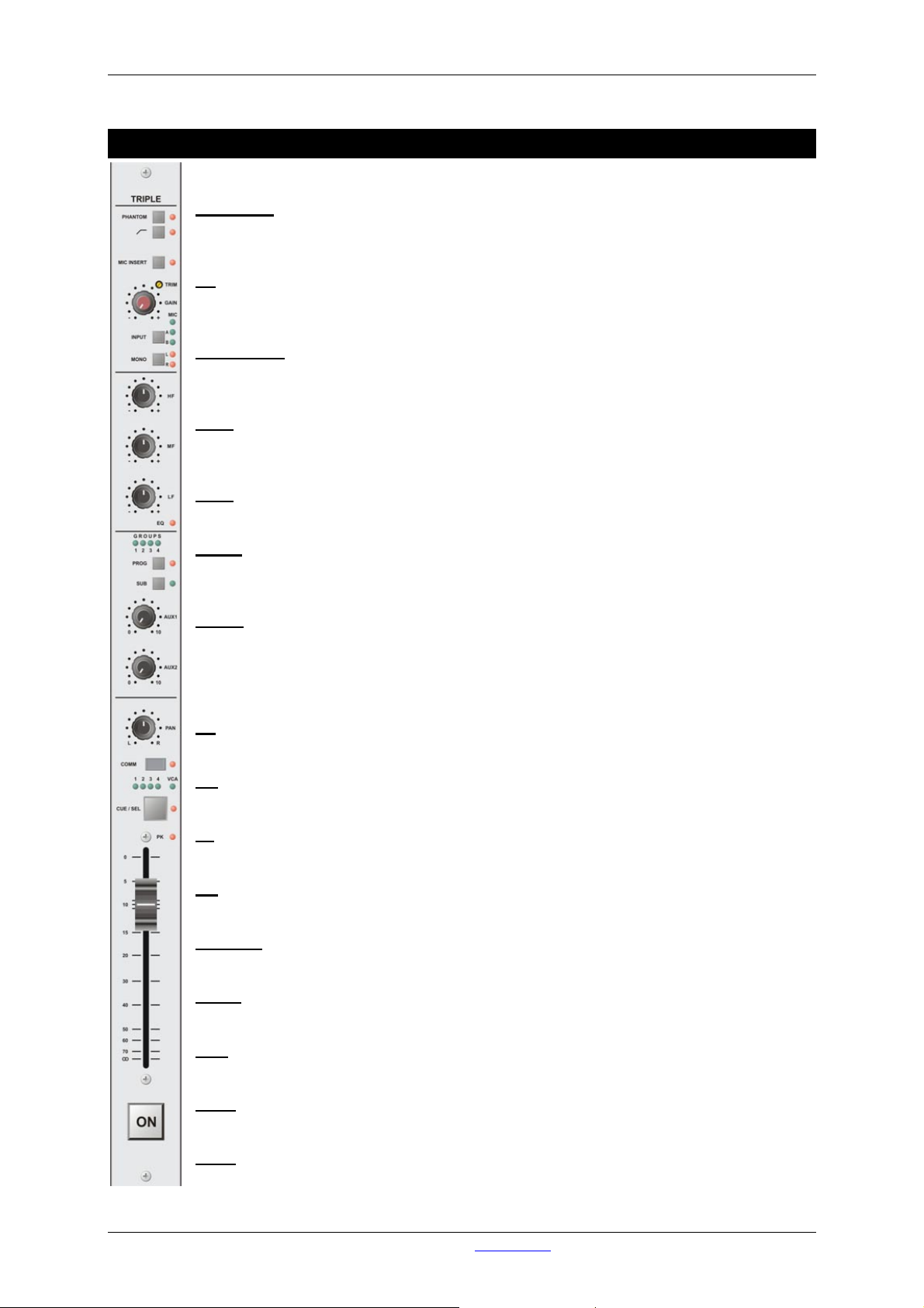
5TRIPLE INPUT STEREO MODULE................................................................................................................ 9
5.1 GENERAL PURPOSE INPUT /OUTPUT .......................................................................................................... 11
6TRIPLE PRO INPUT STEREO MODULE ..................................................................................................... 12
6.1 GENERAL PURPOSE INPUT /OUTPUT .......................................................................................................... 14
7HYBRID MODULE ........................................................................................................................................ 15
7.1 GENERAL PURPOSE INPUT /OUTPUT .......................................................................................................... 17
8TELCO/DIGITAL MODULE........................................................................................................................... 18
8.1 GENERAL PURPOSE INPUT /OUTPUT .......................................................................................................... 20
9GROUP MODULE......................................................................................................................................... 21
9.1 THE GROUP SECTION ............................................................................................................................. 21
9.2 THE VCA SECTION................................................................................................................................... 22
9.3 GENERAL PURPOSE INPUT /OUTPUT .......................................................................................................... 23
10 MASTER MODULE ................................................................................................................................... 24
10.1 THE PROGRAM SECTION........................................................................................................................ 24
10.2 THE CRM SECTION .................................................................................................................................. 25
10.3 GENERAL PURPOSE INPUT /OUTPUT .......................................................................................................... 26
11 STUDIO MODULE..................................................................................................................................... 27
11.1 GENERAL PURPOSE INPUT /OUTPUT .......................................................................................................... 28
12 BACK PANEL OF THE FRAME ............................................................................................................... 29
13 PATCH PANELS....................................................................................................................................... 31
14 WIRING ..................................................................................................................................................... 32
14.1 BACK PANEL FIXED CONNECTIONS ............................................................................................................. 32
14.2 BACK PANEL MODULE CONNECTIONS ......................................................................................................... 32
14.3 PATCH PANELS ........................................................................................................................................ 35
15 JUMPER SETTINGS................................................................................................................................. 37
15.1 TRIPLE ON-AIR INPUT MODULE .............................................................................................................. 37
15.2 TRIPLE (PRO) INPUT MODULE................................................................................................................. 37
15.3 HYBRID MODULE .................................................................................................................................... 37
15.4 TELCO/DIGITAL MODULE....................................................................................................................... 37
15.5 GROUP MODULE .................................................................................................................................... 37
15.6 CRM/STUDIO MODULE ........................................................................................................................... 38
15.7 BACK PANEL ............................................................................................................................................ 38
15.8 LINE I/O XLR PATCH PANEL .................................................................................................................... 38
16 AIRMAX SOFTWARE ............................................................................................................................... 39
16.1 INSTALLATION........................................................................................................................................... 39
16.2 GETTING STARTED ................................................................................................................................... 39
17 SPECIFICATIONS..................................................................................................................................... 41
18 SICO REMOTE UNIT ................................................................................................................................ 42
19 LIST OF FIGURES.................................................................................................................................... 43

Contents
20 LIST OF TABLES...................................................................................................................................... 44
21 DECLARATION OF CONFORMITY.......................................................................................................... 45
22 PRODUCT SAFETY.................................................................................................................................. 46
23 DISCLAIMER ............................................................................................................................................ 49

Package Contents / Introduction
1 Package Contents
The AirMax package comes with the following parts inside.
•1x AirMax System in the configuration you have ordered.
One or more frames containing modules
One power cable per frame
25 pins D Sub cable for every frame minus one
37 pins D Sub cable for every frame minus one
Optional redundant power supply per frame
Optional patch panels
Optional RJ45 Shielded cables
•1x This manual
•1x AirMax software CD-ROM supporting Win2000/WinXP operating systems
•1x USB cable
2 Introduction
This manual will give you a detailed explanation of the functionality of the AirMax and all its features.
It is advisable to read this manual once before touching any control, or even thinking about hooking up the
system.
We know that that is actually the first thing you want to do but please do NOT and discipline yourself to
read the manual first.
The manual gives all sorts of valuable information before getting started and it saves you (and us of
course) from getting in touch with us for all sorts of questions. You can use this manual later on as a
reference.
In the first chapter, we shall give you an overview of the AirMax and its features. In this way, you can have
an impression of how to implement the system in your application.
The next chapters will deal with interconnecting the various parts of the system and its external interfacing
with your equipment
When installing and wiring the AirMax, you can finalize its interfacing with the instructions in the following
chapters.
After installation, you will have a very complete mixer with a human interface that is very logical and
intuitive.

System Structure
3 System Structure
The AirMax is a digitally controlled analogue desktop mixer using the latest, state of the art, digital and
analogue technology housed in an ‘easy to use’ and ‘versatile’ 19” rack chassis which can easily be
mounted drop through in a work surface left or right of your script space.
Purchasing choices are straightforward. There is one welded steel 19” frame with 12 module positions. In
total a maximum of 46 input channels and 1 double sized master module can loaded into 4 frames as a
maximum. This also includes a maximum of 4 stereo group modules and 8 studio modules. Frames
connect with each other by two D Sub connector cables located on the side panels of the frame.
The user interface provides direct intuitive access to all-important functions of the console.
The MIC/line modules come in three flavors so there’s no need for excessive complexity.
A hybrid and TELCO module are available for communication over a telephone line and bringing calls into
the program. Where the hybrid module can be connected directly to the telephone line, the TELCO module
has two stereo line in/outputs which can be connected to an external CODEC. As an option, the TELCO
module can be supplied to have digital in/outputs also making this module suited to act as a simple digital
input module.
The AirMax can be equipped with a maximum of 4 stereo group modules when sub grouping is needed.
The upper section lets you control the audio groups. The VCA groups are positioned in the lower section.
VCA groups can be used to control cue/on/fader of multiple channels with the touch of just one control. An
external fader can be connected to remote control the VCA-Master.
The audio groups have an extra external line input, which makes the AirMax suitable for recording/tape
monitoring if ever needed. Different assignments can be made for audio and VCA groups.
With a maximum of 8 studio modules, the AirMax can be deployed in both small and large setups.
All studio modules have two phones sections and of course a monitor output. Source selection is built in
and also talkback which can be routed to either one of the outputs or to a combination.
An extra meter output gives you the option to hook up your own meters instead of using the internal on
Screen meters.
Every AirMax system needs one double-sized master module. This module contains two sections.
The first section is the program section. This section houses overall gain controls for the two stereo aux
busses and the sub bus. Talkback can be switched on for any of these busses and there’s also a cue
speaker output with it’s own gain control. The COMM and CUE reset buttons allow you to instantly reset all
activated COMM/CUE switches throughout the console. A master fader is present but can be disabled to
suit your needs. The second section of the master module is the CRM section. This section is similar to the
studio module.
With the AirMax, we have incorporated a new way of interfacing with studio equipment by use of high
quality low cost readily available STP cable, also called shielded RJ45 Ethernet cable. In this way not only
a huge amount of inputs/outputs could be created but cabling costs are reduced significantly.
One side of the cable is connected to the back of the AirMax frame and the other end is connected to one
out of five different path panels. Doing it this way the connectors can be brought to the source resulting in
compact and neat cabling.
With a PC connected to the AirMax and using USB cable you can configure all internal settings, remote
control the AirMax and even visually monitor output levels on a meter application. Functionality of many
GPIO’s can be programmed and advanced setup for the communication buss can be made here.
The settings can be saved to and loaded from file. In this way, you have the advantage of instant recall of
all settings enabling you to customize program and user requirements.

Triple ON-AIR Input Stereo Module
4 TRIPLE ON-AIR Input Stereo Module
MIC INSERT
The MIC INSERT led indicates whether a balanced insert is switched in or out of the signal
microphone’s signal path.
TRIM
The TRIM control ads an extra 30dB of gain to the MIC pre-amp.
An optimal gain range setting can be accomplished in this way.
GAIN
The GAIN control adjusts the incoming signal level on the MIC and LINE input.
INPUT
The INPUT switch allows the user to switch input between MIC, LINE A and LINE B.
The associated LEDS indicate which input is currently selected.
MONO
The MONO led indicates if the stereo input signal of this module is switched to summed mono
output signals.
PROG
The PROG(ram) switch assigns the signal in stereo to the PROG(ram) output.
SUB
The SUB switch assigns the signal in stereo to the SUB output.
AUX1
The AUX1 control adjusts the amount of signal send to the stereo AUX 1 bus.
AUX2
The AUX2 control adjusts the amount of signal send to the stereo AUX 2 bus.
PAN
Allows adjustment between the left and right channel outputs.
COMM
The COMM switch enables communication between this channel and anyone who has access
to the COMM bus at the same time.
CUE/SEL
Stereo pre-fade listening allows for pre-fade listening of the channel with the fader closed.
In configuration mode this switch is used to program the modules identity.
PK
The PK led acts as a peak led on the input signal.
FADER
The linear FADER controls a VCA and thereby the module's overall level.
ON
Channel ON/OFF switch. the associated LED will light when the ON switch is activated.
RIAA Plug-in PCB
Optionally a RIAA Plug-in PCB can be inserted into the signal path of LINE B to connect a
gramophone player directly to this input.

Triple ON-AIR Input Stereo Module
4.1 General Purpose Input / Output
The module has several features for remote controlling / signaling. All the general-purpose inputs and
outputs are under software control used in various ways.
ON, CUE, COMM switches and fader functionality can be set-up to trigger one or multiple GPO’s on the
module, studio-mutes, red-lights and local or global cue-resets.
GPO’s can send out pulse or a continuous signals when triggered. Pulses can be generated by on, off
or both.
The module has four GPO’s. When properly connected to an AirMax patch-panel all GPO’s are
connected to one of the Remote jack connectors between the Tip and Ring. By opto-isolated relays the
GPO’s are able to handle a maximum of 50 V at 200 mA.
The module has one MIC GPIO containing a MIC-ON output and a control input on 1 stereo jack.
Tip =LED
Ring =Switch
Sleeve =GND
All these settings are made per individual input, serving different purposes depending on the current
audio source.
4.2 Phantom Power / Low Cut
Phantom power and low cut are available for the MIC input. Both can be enabled or disabled
separately by changes in jumper settings.
This TRIPLE ON-AIR MODULE has no possibility to control these functions by software!

Triple Input Stereo Module
5 TRIPLE Input Stereo Module
PHANTOM
The PHANTOM button toggles 48V phantom power on and off on the MIC input of this
module.
LC
The LC switch toggles the filter on the MIC input on and off. This is a 12 dB per octave
low-cut filter at 80 Hz.
MIC INSERT
The MIC INSERT switch positions a balanced insert in or out of the microphone’s signal
path.
TRIM
The trim control adds an extra 30dB of gain to the MIC pre-amp. An optimal gain range is
set in this way.
GAIN
The GAIN control adjusts the incoming signal level on the MIC and LINE input.
INPUT
The INPUT switch allows the user to switch between MIC, LINE A and LINE B.
The associated LEDS indicate which input is currently selected.
MONO
The MONO switch can convert an incoming signal into a mono signal or accept one and
route it to both outputs of the module. The associated LEDS indicate if mono is currently
active and if either left and right inputs are summed, only the left or only the right input
signal is routed.
HF
Adjusts high frequencies with +/- 12 or 6 dB at 10 kHz shelving.
MF
Adjusts high-mid frequencies with +/- 12 or 6 dB at 1 kHz bell curve.
LF
Adjusts the low frequencies with +/- 12 or 6 dB at 60 Hz shelving.
EQ
The EQ led indicates whether equalization is on or off.
GROUPS
These leds indicate if and to which stereo GROUP this module is assigned.
PROG
The PROG switch assigns the signal in stereo to the PROG output.
SUB
The SUB switch assigns the signal in stereo to the SUB output.
AUX1
The AUX1 control adjusts the amount of signal sent to the stereo AUX 1 bus.
AUX2
The AUX2 control adjusts the amount of signal sent to the stereo AUX 2 bus.

Triple Input Stereo Module
PAN
Allows adjustment between the left and right channel outputs.
COMM
The COMM switch enables communication between this channel and anyone who has
access to the COMM bus at the same time.
VCA
These leds indicate if and by which VCA master this module is currently controlled.
The VCA led gives an indication of the amplitude of the VCA control voltage.
CUE/SEL
CUE/SEL allows for pre-fade listening of the channel with the fader closed.
The CUE switch also acts as a SEL(ECT) switch for the assignment of the module to a
stereo GROUP or VCA master.
In configuration mode this switch is used to program the modules identity.
PK
The PK led acts as a peak led on the input signals.
FADER
The linear fader controls a VCA and thereby the module's overall level.
ON
Channel ON/OFF switch. The associated LED will light when the ON switch is active.
RIAA Plug-in PCB
Optionally a RIAA Plug-in PCB can be inserted into the signal path of LINE B to directly
connect a gramophone player to the input.

Triple Input Stereo Module
5.1 General Purpose Input / Output
The module has several features for remote controlling / signaling. All general purpose in- and outputs are
under software control and used in various ways.
ON, CUE, COMM switches and fader functionality can be set-up to trigger one or multiple GPO’s on the
module, studio-mutes, red-lights and local or global cue-resets.
GPO’s can send out a pulse or a continuous signal when triggered. Pulses can be generated by on, off or
both.
The module has four GPO’s. When properly connected to an AirMax patch-panel all GPO’s are
connected to one of the Remote jack connectors between the Tip and Ring. By opto isolated relays the
GPO’s are able to handle a maximum of 50 V at 200 mA.
GPI’s can be set up to trigger ON, CUE, Cough/Mute and COMM. GPI’s can be switched between
latching or momentary, but when selected the AirMax has the ability to figure this out by itself.
The module has two GPI’s. When properly connected to an AirMax patch-panel all GPI’s have a 5 V
TTL 100 kOhm circuitry connected to one of the Remote jack connectors between the Tip and Ring.
The module has one MIC GPIO containing a MIC-ON output and a control input on one stereo jack.
Tip =LED
Ring =Switch
Sleeve =GND
All these settings are made per individual input, serving different purposes depending on the actual
audio source.

Triple Pro Input Stereo Module
6 TRIPLE PRO Input Stereo Module
PHANTOM
The PHANTOM button toggles 48V phantom power on and off on the MIC input of this
module.
LC
The LC switch toggles the filter on the MIC input on and off. The filter has a 12 dB per
octave low-cut filter at 80 Hz.
MIC INSERT
The MIC INSERT switch positions a balanced INSERT in or out of the microphone’s signal
path.
TRIM
The TRIM control adds an extra 30dB of gain to the MIC pre-amp. An optimal gain range
can be found in this way.
GAIN
The GAIN control adjusts the incoming signal level on the MIC and LINE input.
INPUT
The INPUT switch allows the user to switch input between MIC, LINE A and LINE B.
The associated LEDS indicate which input is currently selected.
MONO
The MONO switch is used to make an incoming signal mono or accept one and route it to
both outputs of the module. The associated LEDS indicate if mono is currently active and
if either left and right inputs are summed or only the left input signal is routed or only the
right.
HF
Adjusts high frequencies with +/- 12 or 6 dB at 12 kHz shelving.
HMF
Adjusts high-mid frequencies with +/- 12 or 6 dB at 5 kHz bell curve.
LMF
Adjusts low-mid frequencies with +/- 12 or 6 dB at 250 Hz bell curve.
LF
Adjusts the low frequencies with +/- 12 or 6 dB at 60 Hz shelving.
EQ
The EQ switch toggles equalization on and off.
GROUPS
These leds indicate if and to which stereo GROUP this module is currently assigned.
PROG
The PROG switch assigns the signal in stereo to the PROG output.
SUB
The SUB switch assigns the signal in stereo to the SUB output, where the SUB control
adjusts the amount of signal send to the SUB output just like an AUX send.

Triple Pro Input Stereo Module
AUX1
The AUX1 control adjusts the amount of signal send to the stereo AUX 1 bus.
AUX2
The AUX2 control adjusts the amount of signal send to the stereo AUX 2 bus.
PAN
Allows adjustment between the left and right channel outputs.
COMM
The COMM switch enables communication between this channel and anyone who has
access to the COMM bus at the same time.
VCA
These leds indicate if and which VCA master currently controls this module.
The VCA led gives an indication of the amplitude of VCA control voltage.
CUE/SEL
CUE/SEL allows pre-fade listening of the channel with the fader closed.
The CUE switch also acts as a SEL(ECT) switch for the assignment of the module to a stereo
GROUP or VCA master.
In configuration mode this switch is used to program the modules id.
FADER
The linear fader controls a VCA and thereby the module's overall level.
The four leds next to the channel fader give an indication of the incoming signal level.
ON
Channel ON/OFF switch. The associated LED will light when the ON switch is active.
RIAA Plug-in PCB
Optionally a RIAA Plug-in PCB can be inserted into the signal path of LINE B to connect a
gramophone player directly to the input.

Triple Pro Input Stereo Module
6.1 General Purpose Input / Output
The module has several features for remote controlling / signaling. All the general purpose inputs and
outputs are under software control and can be used in various ways.
ON, CUE, COMM switches and fader functionality can be set-up to trigger one or multiple GPO’s on the
module, studio-mutes, red-lights and local or global cue-resets.
GPO’s can send out a pulse or a continuous signal when triggered. Pulses can be generated by on, off or
both.
The module has four GPO’s. When properly connected to an AirMax patch-panel all GPO’s are
connected to one of the Remote jack connectors between the Tip and Ring. By opto isolated relays the
GPO’s are able to handle a maximum of 50 V at 200 mA.
GPI’s can be set up to trigger ON, CUE, Cough/Mute and COMM. GPI’s can be switched between
latching or momentary, but when selected the AirMax has the ability to figure this out by itself.
The module has two GPI’s. When properly connected to an AirMax patch-panel all GPI’s have a 5 V
TTL 100 kOhm circuitry connected to one of the Remote jack connectors between the Tip and Ring.
The module has one MIC GPIO containing a MIC-ON output and a control input on 1 stereo jack.
(Tip=LED, Ring=Switch, Sleeve=GND)
All these settings are per individual input, serving different purposes depending on the current audio
source.

Hybrid Module
7 HYBRID Module
TRIM
The TRIM control adjusts the optimum side-tone suppression (RC-balance) and only
needs to be adjusted once with installation.
SEND
The SEND control adjusts the outgoing signal to the Caller.
GAIN
The GAIN control adjusts the incoming signal level on the HYBRID and LINE input.
INPUT
The INPUT switch allows the user to switch input between the internal hybrid and an
external line in. The associated led indicates which input is currently selected.
INSERT
The INSERT switch inserts an external device into the signal path.
HC
The HC control adjusts the 12 dB per octave high cut filter in a range from 1 kHz to off.
LC
The LC control adjusts the12 dB per octave low cut filter in a range from off to 500 Hz.
FILTER
The FILTER led indicates whether the HC/LC filters are on or off.
GROUPS
These leds indicate if and to which stereo GROUP this module is assigned.
PROG
The PROG switch assigns the signal in stereo to the PROG output.
SUB
The SUB switch assigns the signal in stereo to the SUB output.
AUX1
The AUX1 control adjusts the amount of signal send to the stereo AUX 1 bus.
AUX2
The AUX2 control adjusts the amount of signal send to the stereo AUX 2 bus.
PAN
Allows adjustment between the left and right channel outputs.
COMM
The COMM switch enables communication between this channel and anyone who has
access to the COMM bus at the same time.
VCA
These leds indicate if and which VCA master controls this module.
The VCA led gives an indication of the VCA control voltage.

Hybrid Module
CUE/SEL
Stereo pre-fade listening; allows pre-fade listening of the channel with the fader closed.
The CUE switch also acts as a SEL(ECT) switch for the assignment of the module to a
stereo GROUP or VCA master.
In configuration mode, this switch is used to program the modules id.
PK
The PK led acts as a peak led on the input signal.
FADER
The linear fader controls a VCA and the module's overall level.
ON
Channel ON/OFF switch. The associated LED will light when the ON switch is active.

Hybrid Module
7.1 General Purpose Input / Output
This module has several features for remote controlling / signaling. All the general purpose in and outputs
are under software control and can be used in various ways.
ON, CUE, COMM switches and fader functionality can be set-up to trigger one or multiple GPO’s on the
module, studio-mutes, red lights and local or global cue-resets.
GPO’s can send out a pulse or a continuous signal when triggered. Pulses can be generated by on, off
or both.
The module has two GPO’s. When properly connected to an AirMax patch-panel all GPO’s connect to
one of the Remote jack connectors between the Tip and Ring. By way of opto-isolated relays, the
GPO’s are able to handle a maximum of 50 V at 200 mA.
GPI’s can be set up to trigger ON, CUE, Cough/Mute and COMM. GPI’s can be switched between
latching or momentary, but when selected the AirMax has the ability to figure this out on itself.
The module has three GPI’s. When properly connected to an AirMax patch-panel two GPI’s have a 5 V
TTL 100 kOhm circuitry connected to one of the Remote jack connectors between the Tip and Ring.
The third GPI is an internal GPI, which signals when someone is trying to call you.
All these settings are programmed per individual input, serving different purposes depending on the
current audio source.

Telco / Digital Module
8 TELCO/DIGITAL Module
SEND
The SEND control adjusts the outgoing signal level at the SEND A and SEND B outputs.
GAIN
The GAIN control adjusts the incoming signal level on LINE A and LINE B.
INPUT
The INPUT switch allows the user to switch input between LINE A and LINE B.
The associated LEDS indicate which input is currently selected.
MONO
The MONO switch can be used to make an incoming signal mono or accept one and route
it to both outputs of the module. The associated LEDS indicate if the mono switch is
currently active and if either left and right inputs are summed, only the left input signal is
routed through, or only the right.
HF
Adjusts high frequencies with +/- 12 or +/-6 dB at 10 kHz shelving.
MF
Adjusts high-mid frequencies with +/- 12 or +/-6 dB at 1 kHz bell curve.
LF
Adjusts the low frequencies with +/- 12 or +/-6 dB at 60 Hz shelving.
EQ
The EQ led indicates whether equalization is on or off.
GROUPS
These leds indicate if and to which stereo GROUP this module is assigned.
PROG
The PROG switch assigns the signal in stereo to the PROG output.
SUB
The SUB switch assigns the signal in stereo to the SUB output.
AUX1
The AUX1 control adjusts the amount of signal sent to the stereo AUX 1 bus.
AUX2
The AUX2 control adjusts the amount of signal sent to the stereo AUX 2 bus.
PAN
Allows adjustment between the left and right channel outputs.
COMM
The COMM switch enables communication between this channel and anyone who has
access to the COMM bus at the same time.
VCA
These leds indicate if and by which VCA master this module is currently controlled.
The VCA led gives an indication of the amplitude of the VCA control voltage.

Telco / Digital Module
CUE/SEL
CUE/SEL allows for pre-fade listening of the channel with the fader closed.
The CUE switch also acts as a SEL(ECT) switch for the assignment of the module to a stereo
GROUP or VCA Master.
In configuration mode this switch is used to program the modules identity.
PK
The PK led acts as a peak led on the input signal.
FADER
The linear fader controls a VCA and thereby the module's overall level.
ON
Channel ON/OFF switch. The associated LED will light when the ON switch is active.

Telco / Digital Module
8.1 General Purpose Input / Output
The module has several features for remote controlling / signaling. All general purpose in and outputs are
under software control and can be used in various ways.
ON, CUE, COMM switches and fader functionality can be set-up to trigger one or multiple GPO’s on the
module, studio-mutes, red lights and local or global cue-resets.
GPO’s can send out a pulse or a continuous signal when triggered. Pulses can be generated by on, off or
both.
The module has four GPO’s. When properly connected to an AirMax patch-panel all GPO’s are
connected to one of the Remote jack connectors between the Tip and Ring.
Opto isolated relays in the GPO’s are able to handle a maximum of 50 V at 200 mA.
GPI’s can be set up to trigger ON, CUE, Cough/Mute and COMM. GPI’s can be switched between
latching or momentary, but when selected the AirMax has the ability to figure this out by itself.
The module has four GPI’s. When properly connected to an AirMax patch-panel all GPI’s have a 5 V
TTL 100 kOhm circuitry connected to one of the Remote jack connectors between the Tip and Ring.
All these settings are per individual input, serving different purposes depending on the current audio
source.
Table of contents
Other D&R Mixer manuals