Danfoss DEVI 140F0955 User manual

Installation Guide
Connection kit - cable to
cold lead + end termination
(Pipeheat)
Installation Guide - Connection kit - cable to cold lead + end termination (Pipeheat)
EN
DK
FI
NO
SE
Intelligent solutions
with lasting effect
Visit DEVI.com


EN
Installation Guide
DK
FI
Installationsvejledning
Asennusopas
NO
Installasjonsveiledning
SE
Installationsguide

EN Table of contents
1 Introduction........................................................................4
2 Connection kit components .........................................................5
3 Safety instructions ..................................................................6
4 Assembly process ...................................................................8
5 Standard compliance ..............................................................13
6 Warranty . . . . . . . . . . . . . . . . . . . . . . . . . . . . . . . . . . . . . . . . . . . . . . . . . . . . . . . . . . . . . . . . . . . . . . . . . .14
1 Introduction
The connection kit installation guide “Connection kit - cable to cold lead + end termination
(Pipeheat)”describes of the connection muff and end termination. The connection kit cable to is a
connection kit containing the assembly supply of the heat shrink tubes for the connection between
cold tail and self-limiting heating cable and end cap termination of a heating cable.
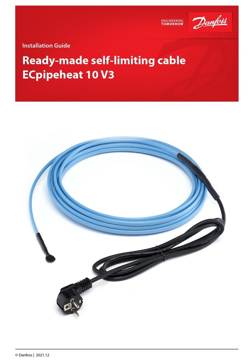
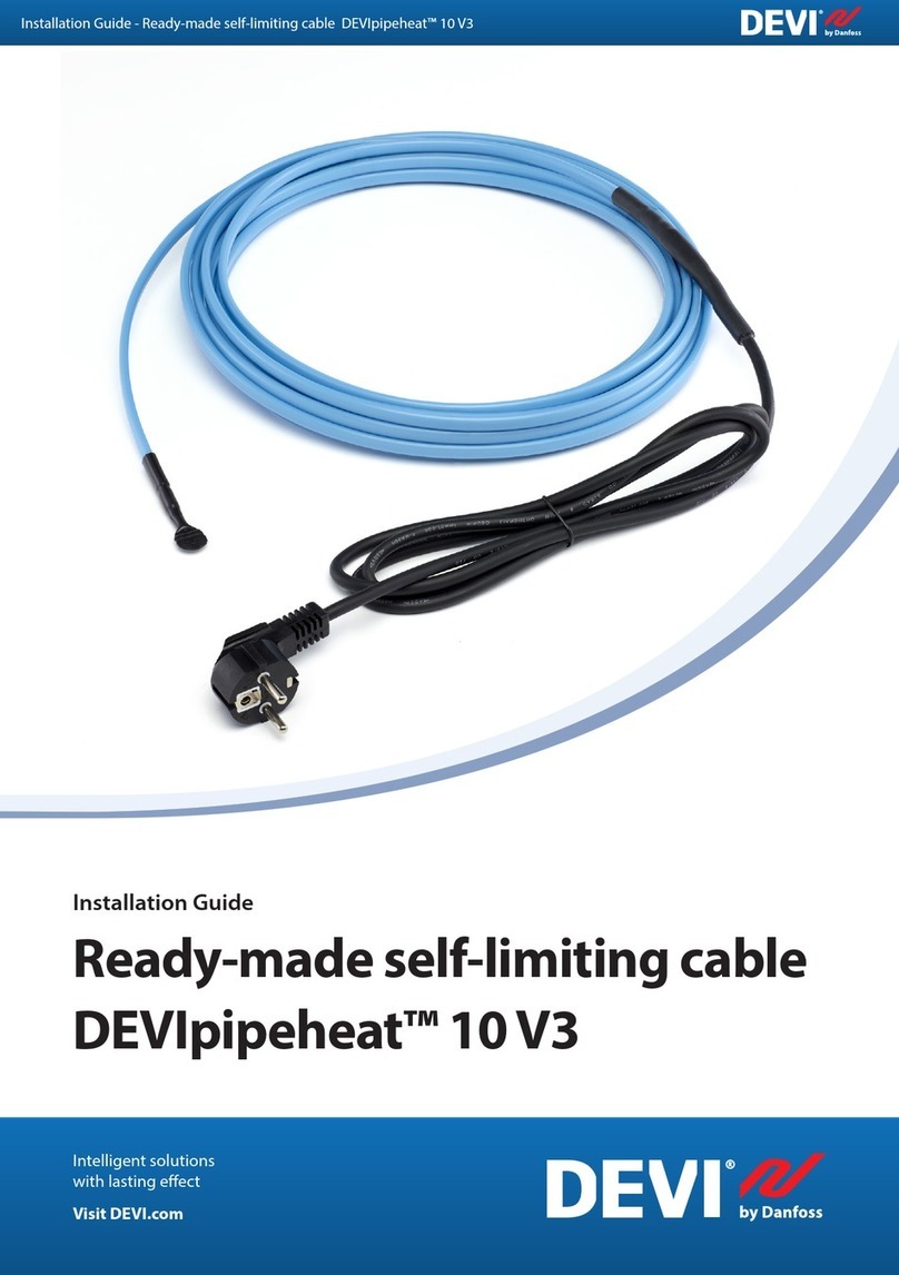
Related products: DEVIpipeheat™ 10 V2/ECpipeheat 10 V2, DEVIpipeheat™ 10 V3/ECpipeheat 10 V3
Product number: 140F0955.
Installation Guide Connection kit - cable to cold lead + end termination (Pipeheat)
DEVI4

EN
2 Connection kit components
For connection between cold lead and heating cable
No. Component Pcs. Designation Dimensions
1 1 19/5 Heat shrink
tube 150 mm
2 1 9/3 Heat shrink
tube 85 mm
3 3 4/1 Heat shrink
tube 45 mm
4 3 Double tubular
rivet 0,5-1,0 mm²
For end cap
No. Component Pcs. Designation Dimensions
1 1 6/1,4 heat shrink
tube 20 mm
2 1 12/3 heat shrink
tube 85 mm
Installation Guide Connection kit - cable to cold lead + end termination (Pipeheat)
5DEVI

EN 3 Safety instructions
The safety instruction defines type of tools and activity, that impacts the installation of the
connection kit in terms of leakage in any losses to the cable including arc.
Tools and equipments
Name Component
Wire cutters
Сrimping pliers
Tape measure
Utility Knife
Heat gun / heating fan
Flat crimping pliers
Multimeter
Installation Guide Connection kit - cable to cold lead + end termination (Pipeheat)
DEVI6

EN
Cautions and warnings
Cautions/Warning Situation Illustration Tips and tricks
1. Risk of fire Short Circuit
Identify the cause
(e.g ensure the aluminum
foil is not twisted)
2. Risk of fire Heat gun / heating fan
damaged
Replace the heat gun /
heating fan.
Risk of burn
Burn to the body from
the heatgun / heating
fan or heated metal
Protection gloves when
using the heat gun.
Electrical shock:
1. Ground fault
protection
disengaged
Cable is damaged Replace the cable where it
is damaged
De-energize all power
circuit
Risk of short circuit
and fire
Double-check that all
power circuits are de-en-
ergized before you work.
Always use ground
fault equipment
protection with
tracing system!
Risk of electrical shock
Damage on the
connection
Humidity inside the
connection or end cap
Replace the connection
system / end cap
Installation Guide Connection kit - cable to cold lead + end termination (Pipeheat)
7DEVI

EN 4 Assembly process
Cable construction design
Heating cable
1
2
3
4
5
6
Layer Name Designation
1 Bus wire Tinned copper
2 Matrix XLPE with carbon black
3 Insulation jacket TPO flame retardant
4 Shield Aluminium polyester
tape – thin drain wire
5 1st Jacket MDPE
6 Outer sheath PVDF
Cold lead
Layer Name
1 Bus wire
2 Wire insulation
3 Inner sheath
4 Outer sheath
Before you start the assembly process you must check the power supply line with the multimeter to
ensure they are de-energized and ensure the control unit is installed according to the installation
instruction provided and check the ground fault protection.
This appliance can be used by children aged from 8 years and above and persons with reduced
physical, sensory, or mental capabilities or lack of experience and knowledge if they have been
supervision or instruction concerning use of the appliance in a safe way and understand the hazards
involved. Children shall not play with the appliance. Cleaning and user maintenance shall not be
made by children without supervision.
Installation Guide Connection kit - cable to cold lead + end termination (Pipeheat)
DEVI8

EN
The assembly process for the “Connection kit - cable to cold lead + end termination (Pipeheat)”is
divided into four processes. The first process covers the assembly process of the ready-making of
the heating cable. The second process covers assembly process of the ready-making of the cold tail.
The third process covers assembly process between the ready-making of the heating cable and cold
tail. The fourth process covers assembly process of the“Sealing the end of the heating cable”for
protection of the end cap.
Ready-making of the heating cable
Drawing Designation Tools
30
- Outer Sheath removed
The outer sheath of the heating cable is
removed over a length of 30 mm.
Wire cutter,
knife and tape
measure
30
- Alu. foil removed
- Drain wires twisted
The aluminum foil screen and drain
wires are released and twisted, to be
used as the ground connection of the
cable.
Knife, and tape
measure
10
20
- Primary insulation removed
Remove 20 mm of the 30 mm insulation
jacket Check after cutting the insulation
cable that 10 mm is left.
Knife and tape
measure
20
10
- Conductor removed
Cut up the core material along one of the
two conductors and release and twist it. The
outermost of the 10 mm of the material is
removed from the other conductor.
Knife
The drain wires is twisted over
the heating cable
The drain wires is twisted over the
heating cable.
Installation Guide Connection kit - cable to cold lead + end termination (Pipeheat)
9DEVI

EN Ready-making of the cold tail
Drawing Designation Tools
50
- Outer sheath removed
Remove 50 mm of the outer sheath Knife and wire
cutter
50
Brown
Blue
Yellow/Green
- Primary insulation removed
Remove the outermost 50 mm of the
secondary insulation too.
Knife and wire
cutter
10
Brown
Blue
Yellow/Green
- Wire insulation removed
Strip off approx. 10 mm of each of
the three conductors. Provided two
conductor cold tail with screen is used,
the screen is released and twisted.
Wire cutter
Assembly process
Drawing Designation Tools
Brown
Blue
Yellow/Green
- Rivets added and squeezed
Now the two cables are ready for assembly.
On the cold lead 1,0 mm² rivets are squeezed
with an appropriate pliers onto the two
conductors and 1,0 mm² are squeezed onto
the ground wire (yellow/green).
Crimping pliers
Brown
Blue
Yellow/Green
150
- Heat shrink tube (Length =
150 mm) put over the cold lead
Now, put the 19/5 heat shrink tube
(length = 150) over the outer sheath of the
cold tail.
45
Yellow/Green
- Heat shrink tube (length =
45 mm) put over the conductors
Now, put the two 4/1 heat shrink tube
(length = 45 mm) over the two conductors
(L (Brown) + N (Blue)) of the cold tail with
the squeezed 1,0 mm² rivets.
85
- Heat shrink tube put over
the heating cable
Now, put the 9/3 heat shrink tube (Length
85 mm) over the outer sheath of the
heating cable. Be aware in this process that
the twisted and released aluminum foil
screen do not provide any damages to the
heat shrink tube.
Installation Guide Connection kit - cable to cold lead + end termination (Pipeheat)
DEVI10
EN
Drawing Designation Tools
Yellow/Green
- Rivet added and squeezed
The two heating cable conductors are
connected with the two 1,0 mm² rivets of
the two cold tail conductors (L (Brown) +
N (Blue)). The rivets are squeezed onto it.
Crimping plier /
wire cutter
Yellow/Green
- Heat shrink tube shrunk over
the rivets
Now, put the two 4/1 heat shrink tube
(Length 45 mm) over the two 1,0 riveted
conductors. Make sure they reach the
primary insulation of the heating cable and
over the wire completely.
Beginning at the middle of the heat shrink
tube, shrink the tube at a temperature
275 °F / 135 °C towards the ends of the heat
shrink tube.
Heat gun /
heating fan
- Heat shrink tube
(length = 85 mm) shrunk over the
conductors.
- Heat shrink tube (length =
45 mm) put over the ground wire.
Now, put 4/1 heat shrink tube (Length
85 mm) over the connection to ensure that
the screen/ground wire is still free. , and put
the 4/1 heat shrink tube (length = 45 mm)
over the ground wire. Be aware the heat
shrink tube is not damaged during this
process.
Crimping pliers
Beginning at the middle of the heat shrink
tube, shrink the tube at a temperature
275 °F / 135 °C towards the ends of the heat
shrink tube.
Heat gun /
Heating fan
- Rivets added and squeezed
The heating cable screen is connected with
the 1,0 mm² rivet to the cold tail ground
wire. The rivet is squeezed onto it with an
appropriate pliers.
- Heat shrink tube shrunk over
ground
Now, put 4/1 heat shrink tube (Length
45 mm) over the rivet and shrunk down
from the middle towards the ends.
Heat gun /
heating fan
min.18
min.18
Heat shrink tube (length =
150 mm) shrunk over the
connection.
Now, put the 19/5 heat shrink tube (Length
150 mm) over the entire connection.
Installation Guide Connection kit - cable to cold lead + end termination (Pipeheat)
11DEVI

EN Drawing Designation Tools
Beginning at the middle of the heat shrink
tube, shrink the tube at a temperature
275 °F / 135 °C towards the ends of the heat
shrink tube.
Heat gun /
heating fan
Make sure that the glue is running from
both ends of the heat shrink tube. Now the
assembly is finished.
Sealing the and of the heating cable
Drawing Designation Tools
15
- Outer sheath removed
- Aluminum foil removed
- Drain wires removed
- Insulated matrix, cut at an
angle of approximately 45° on
the flat side to remove some
of one of the conductors. This
is to obtain sufficient distance
between conductors.
Cut 15 mm of the outer sheath, and cut off
the aluminum foil and drain wires from the
15 mm stripped cable too.
Cut insulated matrix at an angle of
approximately 45° on the flat side to remove
some of one of the conductors. Be careful
not to damage the insulation.
Wire cutter,
knife and tape
measure
1
5
- 20 mm small heat shrink tube is
put on over the end of the heat-
ing cable. 5 mm must still be
free of the cable
Now, put the 6/1,4 heat shrink tube (Length =
20 mm) over the end of the cable to the edge
of the removed outer sheath. 5 mm of the
crimp tube must still be free of the cable.
1
5
- 5 mm of small heat shrink tube
is squeezed while still hot. Press
flat with a flat pliers
Beginning at the middle of the heat shrink
tube, shrink the tube at a temperature
275 °F / 135 °C towards the ends of the heat
shrink tube. Immediately after this the 5 mm
are squeezed together on the end with a flat
pliers. Make sure that the glue is running out
from both ends of the crimp tube.
Installation Guide Connection kit - cable to cold lead + end termination (Pipeheat)
DEVI12

EN
Drawing Designation Tools
85
- 85 large heat shrink tube is put
in over the end cable.
Now, put the 12/3 heat shrink tube
(Length = 85 mm) over the end of the cable
to the edge of the removed outer sheath.
22
- Approx. 22 mm large heat
shrink tube must stay on the
heating cable.
- The rest of the shrink tube is
squeezed while still hot.
Beginning at the end of the heat shrink
tube, shrink the tube at a temperature
275 °F / 135 °C towards the other end of the
heat shrink tube positioned over the cable.
Make sure that the glue is running out from
the end of the end sealing.
The heating cable is sealed/terminated
5 Standard compliance
• IEC 60800 Heating cables with a rated voltage of 300/500 V for comfort heating and prevention
of ice formation.
• KTW-BWGL - Testing and inspections on products and materials in contact with drinking water
(end termination).
Holder Danfoss A/S
Product name, and relevant article number Refer to the product label
Production site Refer to the product label
Traceability to the production To be found on insulation inside the cable
Cable length, nominal voltage, IP class, etc. Refer to the product label
The registered trademark of Boverket No 241 217
Certification Body Kiwa Certification AB
Accreditation number 1913
Type Approval No TG 1747
Inspection Body Danish Technological Institute (DTI)
Installation Guide Connection kit - cable to cold lead + end termination (Pipeheat)
13DEVI

EN 6 Warranty
A 2-year product warranty is valid for:
• accessories: “Connection kit - cable to cold lead +
end termination (Pipeheat)”.
Should you, against all expectations, experience a
problem with your DEVI product, you will find that
Danfoss offers DEVIwarranty valid from the date of
purchase on the following conditions: During the
warranty period Danfoss shall offer a new comparable
product or repair the product if the product is found
to be faulty by reason of defective design, materials or
workmanship. The repair or replacement.
The decision to either repair or replace will be solely at
the discretion of Danfoss. Danfoss shall not be liable
for any consequential or incidental damages including,
but not limited to, damages to property or extra
utility expenses. No extension of the warranty period
following repairs undertaken is granted.
The warranty shall be valid only if the WARRANTY
CERTIFICATE is completed correctly and in accordance
with the instructions, the fault is submitted to the
installer or the seller without undue delay and
proof of purchase is provided. Please note that the
WARRANTY CERTIFICATE must be filled in, stamped
and signed by the authorized installer performing
the installation (Installation date must be indicated).
After the installation is performed, store and keep the
WARRANTY CERTIFICATE and purchase documents
(invoice, receipt or similar) during the whole warranty
period.
DEVIwarranty shall not cover any damage caused by
incorrect conditions of use, incorrect installation or if
installation has been carried out by non-authorized
electricians. All work will be invoiced in full if Danfoss
is required to inspect or repair faults that have arisen
as a result of any of the above. The DEVIwarranty shall
not extend to products which have not been paid
in full. Danfoss will, at all times, provide a rapid and
effective response to all complaints and inquiries from
our customers.
The warranty explicitly excludes all claims exceeding
the above conditions.
For full warranty text visit www.devi.com.
devi.danfoss.com/en/warranty/
WARRANTY CERTIFICATE
The DEVIwarranty is granted to:
Address Stamp
Purchase date
Product Art. No.
Installation Date
& Signature
Connection Date
& Signature
Installation Guide Connection kit - cable to cold lead + end termination (Pipeheat)
DEVI14

DK
Indholdsfortegnelse
1 Introduktion.......................................................................15
2 Tilslutningssæt, komponenter . . . . . . . . . . . . . . . . . . . . . . . . . . . . . . . . . . . . . . . . . . . . . . . . . . . . . .16
3 Sikkerhedsinstruktioner ...........................................................17
4 Monteringsproces .................................................................19
5 Overholdelse af standard...........................................................24
6 Garanti............................................................................25
1 Introduktion
Installationsvejledningen ”Tilslutningskabelsæt – kabel til kold tilledning + endeterminering
(Pipeheat)”beskriver tilslutningsmuffen og endetermineringen. Tilslutningskabelsæt er et
tilslutningssæt, der indeholder montageforsyningen af krympeflex til forbindelsen mellem
koldkabel og selvbegrænsende varmekabel samt endehætteterminering af et varmekabel.
Relaterede produkter: DEVIpipeheat™ 10 V2/ECpipeheat 10 V2, DEVIpipeheat™ 10 V3/
ECpipeheat 10 V3
Varenummer: 140F0955.
Installationsvejledning Tilslutningskabelsæt – kabel til kold tilledning + endeterminering (Pipeheat)
15DEVI

DK
2 Tilslutningssæt, komponenter
Til placering af forbindelse mellem kold tilledning og varmekabel
Nr. Komponent Stk. Betegnelse Mål
1 1 19/5 krympeflex 150 mm
2 1 9/3 krympeflex 85 mm
3 3 4/1 krympeflex 45 mm
4 3 Dobbelt rørnitte 0,5-1,0 mm²
Til endehætte
Nr. Komponent Stk. Betegnelse Mål
1 1 6/1,4 krympeflex 20 mm
2 1 12/3 krympeflex 85 mm
Installationsvejledning Tilslutningskabelsæt – kabel til kold tilledning + endeterminering (Pipeheat)
DEVI16

DK
3 Sikkerhedsinstruktioner
Sikkerhedsinstruktionen definerer typen af værktøj og aktivitet, der påvirker installationen af
tilslutningssættet med hensyn til lækage i tilfælde af tab i kablet, herunder lysbue.
Værktøj og udstyr
Navn Komponent
Bidetang
Krympetang
Målebånd
Universalkniv
Varmepistol/varmeblæser
Flad krympetang
Multimeter
Installationsvejledning Tilslutningskabelsæt – kabel til kold tilledning + endeterminering (Pipeheat)
17DEVI

DK Forsigtighedsregler og advarsler
Forsigtighedsregler/
advarsler Situation Illustration Tips og tricks
1. Brandfare Kortslutning
Find årsagen (f.eks. sørg
for, at aluminiumsfolien
ikke er snoet)
2. Brandfare Varmepistol/varme-
blæser beskadiget
Udskift varmepistol/
varmeblæser.
Forbrændingsfare
Forbrænding af
kroppen fra varmepis-
tolen/varmeblæseren
eller opvarmet metal
Beskyttelseshandsker ved
brug af varmepistolen.
Elektrisk stød:
1. Jordfejlsbeskyttelse
deaktiveret
Kabel er beskadiget Udskift kablet, hvis det er
beskadiget
Afbryd alle
strømkredse
Risiko for kortslutning
og brand
Kontrollér igen, at alle
strømkredse ikke er
spændingsførende, før der
arbejdes.
Brug altid
jordfejlsudstyrs-
beskyttelse med
sporingssystem!
Fare for elektrisk stød
Beskadigelse af
forbindelsen
Luftfugtighed inden
i tilslutningen eller
endehætten
Udskift tilslutningssystem/
endehætte
Installationsvejledning Tilslutningskabelsæt – kabel til kold tilledning + endeterminering (Pipeheat)
DEVI18

DK
4 Monteringsproces
Kabelkonstruktion
Varmekabel
1
2
3
4
5
6
Lag Navn Betegnelse
1 Buskabel Fortinnet kobber
2 Matrix XLPE med carbon black
3 Lederisolering TPO flammehæmmende
4 Skærm Aluminiumpolyestertape – tynd
drænledning
5 Mellemkappe MDPE
6 Yderkappe PVDF
Kold tilledning
Lag Navn
1 Leder
2 Lederisolering
3 Inderkappe
4 Yderkappe
Før monteringen påbegyndes, skal du kontrollere strømforsyningsledningen med multimeteret for
at sikre, at den ikke er spændingsførende, og at styreenheden er installeret i overensstemmelse med
den medfølgende installationsvejledning, og kontrollere jordfejlbeskyttelsen.
Dette apparat kan anvendes af børn i alderen 8 år og derover samt af personer med nedsatte
fysiske, mentale eller sensoriske evner eller manglende erfaring og viden, hvis de er under opsyn
eller er blevet instrueret i sikker brug af apparatet og forstår de farer, som anvendelse af apparatet
indebærer. Børn må ikke lege med apparatet. Rengøring og brugervedligeholdelse må ikke udføres
af børn uden opsyn.
Installationsvejledning Tilslutningskabelsæt – kabel til kold tilledning + endeterminering (Pipeheat)
19DEVI

DK
Monteringsprocessen for ”Tilslutningssæt – kabel til kold tilledning + endeterminering (Pipeheat)”
er opdelt i fire processer. Første trin omfatter klargøring af varmekablet. Andet trin omfatter
klargøring af koldkablet. Tredje trin omfatter samling af varmekablet og den kolde tilledning. Fjerde
trin dækker udførelse af endeafslutning og beskyttelse af varmekablets ende.
Klargøring af varmekablet
Tegning Betegnelse Værktøj
30
– Yderkappe ernet
Varmekablets yderkappe ernes over en
længde på 30 mm.
Bidetang, kniv og
målebånd
30
– Alufolie ernet
– Drænledninger snoede
Aluminiumsfolieskærmen og
drænledningerne frigøres og snoes, så
de kan bruges som jordforbindelse for
kablet.
Kniv og
målebånd
10
20
– Lederisolering ernet
20 mm af lederisoleringen ernes, så der
er 10mm mellemkappe tilbage.
Kniv og
målebånd
20
10
– Leder ernet
Skær kernematerialet op langs en af de
to ledere, hvorefter lederen frigøres og
snoes. Fjern det yderste 10 mm materiale af
materiale af den anden leder.
Kniv
Drænledningerne snoes og
bøjes bagud
Drænledningerne snoes bagud
Klargøring af koldkablet
Tegning Betegnelse Værktøj
50
– Yderkappe ernes
Fjern 50 mm af yderkappen Kniv og bidetang
Installationsvejledning Tilslutningskabelsæt – kabel til kold tilledning + endeterminering (Pipeheat)
DEVI20
Table of contents
Languages:
Other Danfoss Cables And Connectors manuals

Danfoss
Danfoss ECpipeguard 10 User manual

Danfoss
Danfoss DEVIpipeheat 10 V3 User manual

Danfoss
Danfoss 088L0023 User manual

Danfoss
Danfoss DEVIpipeheat 10 V3 User manual

Danfoss
Danfoss FIA SS 15-65 User manual

Danfoss
Danfoss VMBQO23H User manual

Danfoss
Danfoss ECpipeheat 10 V3 User manual

Danfoss
Danfoss 176F1742 User manual

Danfoss
Danfoss ECasphalt User manual

Danfoss
Danfoss DEVIpipeguard LSZHT User manual