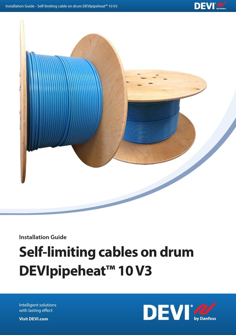
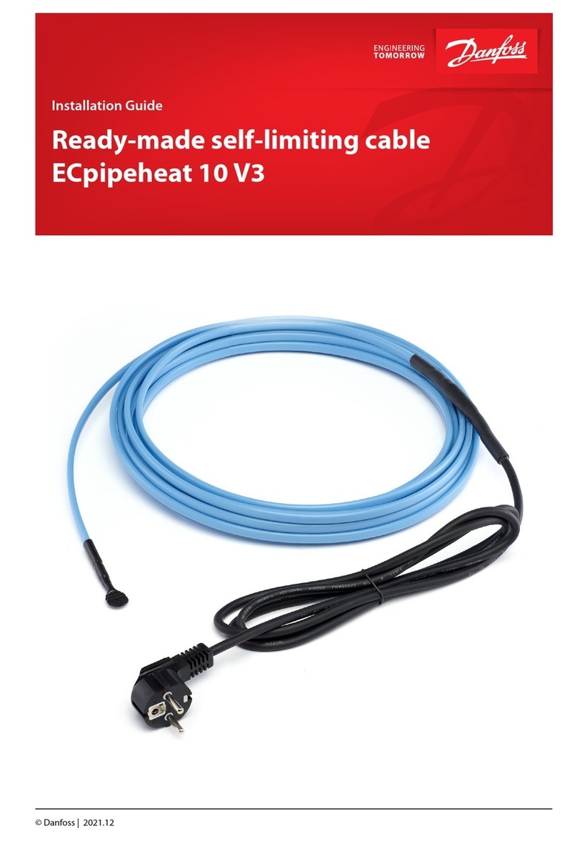
Danfoss DEVIpipeheat 10 V3 User manual

Installation Guide
Ready-made self-limiting cable
DEVIpipeheat™ 10 V3
Installation Guide - Ready-made self-limiting cable DEVIpipeheat™ 10 V3
Intelligent solutions
with lasting eect
Visit DEVI.com


EN
Installation Guide
DK
EE
FI
LT
LV
Installationsvejledning
Paigaldusjuhend
Asennusopas
Montavimo vadovas
Uzstādīšanas rokasgrāmata
NO
Installasjonsveiledning
RU
Руководство по установке
SE
Installationshandbok

Installation Guide Ready-made self-limiting cable DEVIpipeheat™ 10 V3
Table of Contents
1 Introduction. . . . . . . . . . . . . . . . . . . . . . . . . . . . . . . . . . . . . . . . . . . . . . . . . . . . . . . . . . . . . . . . . . . . . . . . . . . . . . . . . . . . . . . . . . . .5
2 Safety instructions . . . . . . . . . . . . . . . . . . . . . . . . . . . . . . . . . . . . . . . . . . . . . . . . . . . . . . . . . . . . . . . . . . . . . . . . . . . . . . . . . . . . . 5
3 Installation guidelines . . . . . . . . . . . . . . . . . . . . . . . . . . . . . . . . . . . . . . . . . . . . . . . . . . . . . . . . . . . . . . . . . . . . . . . . . . . . . . . . .5
4 Application/Product overview . . . . . . . . . . . . . . . . . . . . . . . . . . . . . . . . . . . . . . . . . . . . . . . . . . . . . . . . . . . . . . . . . . . . . . . . .5
5 Thermostats/controllers . . . . . . . . . . . . . . . . . . . . . . . . . . . . . . . . . . . . . . . . . . . . . . . . . . . . . . . . . . . . . . . . . . . . . . . . . . . . . . .7
6 Accessories. . . . . . . . . . . . . . . . . . . . . . . . . . . . . . . . . . . . . . . . . . . . . . . . . . . . . . . . . . . . . . . . . . . . . . . . . . . . . . . . . . . . . . . . . . . . .8
6.1 Fixing elements . . . . . . . . . . . . . . . . . . . . . . . . . . . . . . . . . . . . . . . . . . . . . . . . . . . . . . . . . . . . . . . . . . . . . . . . . . . . . . . . . . . .8
7 Typical installations . . . . . . . . . . . . . . . . . . . . . . . . . . . . . . . . . . . . . . . . . . . . . . . . . . . . . . . . . . . . . . . . . . . . . . . . . . . . . . . . . . . . 9
7.1 Typical pipe tracing installation . . . . . . . . . . . . . . . . . . . . . . . . . . . . . . . . . . . . . . . . . . . . . . . . . . . . . . . . . . . . . . . . . . . . .9
6 Standard compliance . . . . . . . . . . . . . . . . . . . . . . . . . . . . . . . . . . . . . . . . . . . . . . . . . . . . . . . . . . . . . . . . . . . . . . . . . . . . . . . . .11
7 Warranty . . . . . . . . . . . . . . . . . . . . . . . . . . . . . . . . . . . . . . . . . . . . . . . . . . . . . . . . . . . . . . . . . . . . . . . . . . . . . . . . . . . . . . . . . . . . . .12
DEVI4

Installation Guide Ready-made self-limiting cable DEVIpipeheat™ 10 V3
1 Introduction
In this installation guide, the phrase“heating cable”refers to
ready-made self-limiting cable DEVIpipeheat™ 10 V3.
To get the full installation guide, warranty registration, product
information, tips & tricks, addresses, etc.visit www.devi.com
.
2 Safety instructions
Heating cables must always be installed according to local
building regulations and wiring rules as well as the guidelines
in this installation manual.
• De-energize all power circuits and do not connect the plug
to an outlet until installation is completed.
• Residual current device (RCD) protection is required. RCD trip
rating is max. 30 mA.
• Maximum fuse size is 10 A.
• In case of plug cutting the screen from each heating cable must
be connected to earthing terminal or plug must be connected
to outlet, securing a reliable grounding of the screen in accord-
ance with local electricity regulations.
• In case of plug cutting heating cables must be connected via
a switch providing all pole disconnection.
• The heating cable must be equipped with a correctly sized
fuse or circuit breaker according to local regulations.
• Never exceed the maximum heat density (W/m or W/m²) for
the actual application. Refer to Application Guide.
• Heating cable must be used together with an appropriate
thermostat to secure against overheating and reduce energy
consumption.
• The cold lead is not allowed to be replaced by the user. If
cold lead is damaged, it must be replaced by service agent or
similarly qualied persons in order to avoid a hazard.
• This appliance can be used by children aged from 8 years
and above and persons with reduced physical, sensory or
mental capabilities or lack of experience and knowledge if
they have been given supervision or instruction concern-
ing use of the appliance in a safe way and understand the
hazards involved. Children shall not play with the appliance.
Cleaning and user maintenance shall not be made by chil-
dren without supervision.
CAUTION: If the cable is installed inside a drinking water pipe,
it is a precondition for the certication for in drinking water
application, to secure that the water does not reach a tempera-
ture of 23 °C or above.It is a must to secure the installation by a
thermostat with a set-point of +5 °C.
The presence of a heating cable must
• Be made evident by axing caution signs in the fuse box
and in the distribution board or markings at the power
connection ttings and/or frequently along the circuit line
where clearly visible (tracing).
• Be stated in any electrical documentation following the
installation.
3 Installation guidelines
• It is not recommended to install heating cables at tempera-
tures below -5°C.
• Heating cable bending diameter must be minimum 50 mm
(to the inside of the cable).
• Do not bend and pull connections.
• Ensure that the cable is suciently xed and mounted
according to the installation guide.
• The heating cables must be temperature controlled. See
safety instructions.
• Ensure controllers and sensors are connected according to
the applicable installation guide and/or application guide.
• Measure, verify and record insulation resistance during
installation.
• Persons involved in the installation and testing of electrical
trace heating systems shall be suitably trained in all special
techniques required. Installations are intended to be carried
out under the supervision of a qualied person.
4 Application/Product overview
Pipe frost protection Tank frost protection
DEVIpipeheat™ 10 V3
DEVIpipeheat™ 10 V3 is designed for preventing frozen water pipes. DEVIpipeheat™ 10 V3 can be used on the outside of the
water pipe and will heat through the pipe and prevent it from freezing. DEVIpipeheat™ 10 V3 can also be installed inside water
pipe, by using the dedicated tting. It is certied to be suitable for drinking and common water pipes and is designed to be
installed on pipe in all countries and inside pipe in certied countries (DK, EE, FI, LT, LV, SE, NO, RU), on the condition that water
temperature is always kept below 23 °C.
On water pipe installation In water pipe installation
5DEVI
Installation Guide Ready-made self-limiting cable DEVIpipeheat™ 10 V3
Product specication
Type Value
Nominal voltage 230 V~
Nominal output (tolerance) 10 W/m @ 10 °C (7,5-13,5 W/m @ 10 °C )
Max. permissible use temperature, powered 65 °C
Max. permissible use temperature, unpowered 65 °C
Minimum installation temperature - 5 °C
Max. water temperature (inside water pipe installation) 23 °C
Max. water pressure (inside water pipe installation) 10 bar
Heating cable dimensions 8,75 × 5,15 mm
Outer sheath HDPE + blue PVDF
Minimum Screen Coverage 100% aluminium foil
Maximum resistance of protective aluminum foil and drain wire 36 Ω/Km
Bending Ø, min. 50 mm (to the inside of the cable)
Cold lead with plug 2 m, 3 х 0,75 mm²
IP Class for ready made unit
IP Class for heating part and end termination
IP67
IP68
Specic heating cable length can be chosen from product range and used for dierent suitable projects. For more details contact
your local DEVI sales company.
Note: In case of cold lead extension it is the full responsibility of the installer/designer to use proper cold lead dimensioned
for the purpose and assembly sets that establish sucient mechanical strength, ammability resistance and water proong
- and to design the heating unit with correct output for the specic application to avoid overheating of the cable or
building materials.
Regarding other types of applications please contact your local DEVI sales company.
More information about applications (maximum linear output, specic output, heating circuit length, voltage etc.) can be found
at www.devi.com
DEVI6

Installation Guide Ready-made self-limiting cable DEVIpipeheat™ 10 V3
5 Thermostats/controllers
Pipe frost protection Tank frost protection
DEVIreg™ 330
DEVIreg™ 610
DEVIreg™ Multi
The DEVIreg™ thermostat/controller must be commissioned as prescribed in the installation instruction for the actual controller
and adjusted where local conditions vary in relation to factory settings. Before every heating season or at least once per year,
check for faults in the switchboard, thermostat and sensors.
Each heating cable screen must be earthed in accordance with local electric regulations and connected to a residual current
device (RCD).
The heating cables must be temperature controlled and not operate at ambient temperature higher than 5 °C.
More information about thermostats and controllers can be found at www.devi.com.
Sensors:
• Sensors can be live (230 V) components and must be treated according to specic Installation Guide and local standards.
• Sensors can be extended using cable with the same cable construction and cross sections (up to 50 m).
• See section 7 for specic installations.
1
2
3
4
5
1 - Controller; 2 - DIN-rail; 3 - Electric cabinet; 4 - Cold lead connection; 5 - Sensor connection
7DEVI

Installation Guide Ready-made self-limiting cable DEVIpipeheat™ 10 V3
6 Accessories
A comprehensive range of accessories for self- limiting cables is available.
In order to nd all accessories please refer to Product Catalogue or visit www.devi.com
6.1 Fixing elements
DEVI Aluminium Tape (19805078)
For ensuring ecient heat transfer.
3/4" + 1" Pipe tting for DEVIpipeheat™ 10 V3
(140F0956)
Wadding for internal mounting in pipe
Rubber conic sliced sleeve, oval hole.
Max. water pressure – 10 Bar at max. water temperature 23 °C.
DEVI8

Installation Guide Ready-made self-limiting cable DEVIpipeheat™ 10 V3
7 Typical installations
7.1 Typical pipe tracing installation
On water pipe installation
1
2
3
4
5
Fig. 1
1. Apply aluminum tape below (mandatory for
plastic pipes) and on top on the whole length
of the cable.
2. Insulate the pipe with at least 30 mm insula-
tion or thicker if required based on heat loss
calculation.
45°
90°
45°
90°
45°
90°
45°
90°
1
3
Fig. 2
1 - Heating cable; 2 - Aluminum tape; 3 - Wire sensor; 4 - Insulation; 5 - Warning label/tape
In water pipe installation
1
2
3
4
5
6
Fig. 3
1. Fit a T-shaped pipe of a generous size over the pipe
(3/4" and 1").
2. Fit the clean wadding (without side thread or sharp
edges) inside the T-shaped pipe with small hole in
the center.
3. Keep the cable clean and push the cable through
the wadding to facilitate the installation. The con-
nection between heating cable and connecting
cable must be outside the wadding. Mount the
wadding in the following sequence:
• use only clean tools before installation as
heating cable could be in contact with drinking
water;
• rst you put the nut on facing the connection;
• mount the washer on the cable;
• mount the threaded part with the threaded part
facing the end of the cable;
• insert almost whole length of the cable inside of
the pipe, leave approx. 0,5 m of cable to install
rubber seal afterwards;
• the heating cable must extended straight
through the T-shaped pipe;
• install rubber seal on the cable. The conic rubber
seal has slice for heating cable.
4. Turn the nut until it ts tightly (max. torque for pipe
tting is 30 N·m).
5. Insulate the pipe with at least 30 mm insulation or
thicker if required based on heat loss calculation.
1 - Heating cable; 2 - Aluminum tape; 3 - Wire sensor; 4 - Insulation;
5 - Warning label/tape; 6 - 3/4" + 1" Pipe tting
9DEVI

Installation Guide Ready-made self-limiting cable DEVIpipeheat™ 10 V3
1. Check the pipe system to be heated
and make sure that the pipes are dry,
smooth and tight. Check and prepare
the switch board.
2. Draw a plan positioning cable(s),
sensors and thermostat, cable
connections, cold tail, connection box,
cable paths and switch board.
3. Check the insulation resistance of
the heating cables. The measured value
shall be no less than 50 MΩ.
4. Straight lines and sensor must
be tted as shown at Fig.2. Twisted
lines are attached as shown for every
approx.1 m pipe with aluminum tape.
5. Apply aluminum tape below
(mandatory for plastic pipes) and on
top on the whole length of the cable.
Make sure that the cables do not cross
sharp edges.
6. For in pipe installation use 3/4" + 1"
Pipe tting for DEVIpipeheat™ 10 V3
to t cable inside of pipe. Max. water
pressure – 10 Bar at max. water
temperature 23 °C. Max. torque for pipe
tting is 30 N·m.
7. Attach and cover the sensor on top
of the pipe with aluminum tape. Extend
cold tails/leads and keep connections
dry. Mount connection box on the pipe
or close to it and install the thermostat
on the pipe or near it (depends on
thermostat).
8. Re-check the insulation resistance.
Connect cables to connection boxes
and to the switch board.
9. After insulation, place safety marking
tape on the insulation jacket or pipe
trenches for every 5 m. In subsurface
installations, a cover ribbon with a
warning sign must be laid 10 cm above
the cables.
DEVI10

Installation Guide Ready-made self-limiting cable DEVIpipeheat™ 10 V3
6 Standard compliance
EN/IEC 60335-1 Household and similar electrical appliances -
Safety - Part 1: General requirements.
KTW-BWGL - Testing and inspections on products and
materials in contact with drinking water.
Holder Danfoss A/S
Product name, and relevant article number Refer to the product label
Production site Refer to the product label
Traceability to the production To be found on insulation inside the cable
Cable length, nominal voltage, IP class, etc. Refer to the product label
The registered trademark of Boverket No 241 217
Certication Body Kiwa Certication AB
Accreditation number 1913
Type Approval No TG 1747
Inspection Body Danish Technological Institute (DTI)
11DEVI

Installation Guide Ready-made self-limiting cable DEVIpipeheat™ 10 V3
7 Warranty
A 5-year product warranty is valid for:
• self-limiting cables: DEVIpipeheat™ 10 V3.
Should you, against all expectations, experience a problem with
your DEVI product, you will nd that Danfoss oers DEVIwarranty
valid from the date of purchase that was no later than 2 years from
production date on the following conditions: During the warranty
period Danfoss shall oer a new comparable product or repair the
product if the product is found to be faulty by reason of defective
design, materials or workmanship.The repair or replacement.
The decision to either repair or replace will be solely at the discre-
tion of Danfoss. Danfoss shall not be liable for any consequential
or incidental damages including, but not limited to, damages to
property or extra utility expenses. No extension of the warranty
period following repairs undertaken is granted.
The warranty shall be valid only if the WARRANTY CERTIFICATE is
completed correctly and in accordance with the instructions, the
fault is submitted to the installer or the seller without undue delay
and proof of purchase is provided. Please note that theWARRANTY
CERTIFICATE must be lled in, stamped and signed by the author-
ized installer performing the installation (Installation date must
be indicated). After the installation is performed, store and keep
the WARRANTY CERTIFICATE and purchase documents (invoice,
receipt or similar) during the whole warranty period.
DEVIwarranty shall not cover any damage caused by incorrect con-
ditions of use, incorrect installation or if installation has been car-
ried out by non-authorized electricians. All work will be invoiced in
full if Danfoss is required to inspect or repair faults that have arisen
as a result of any of the above.The DEVIwarranty shall not extend
to products which have not been paid in full. Danfoss will, at all
times, provide a rapid and eective response to all complaints and
inquiries from our customers.
The warranty explicitly excludes all claims exceeding the above
conditions.
For full warranty text visit www.devi.com.
devi.danfoss.com/en/warranty/
WARRANTY CERTIFICATE
The DEVIwarranty is granted to:
The insulation resistance shall be measured by means of a DC voltage of at least 500 V for one minute.
The measured value shall be no less than 50 MΩ.
Address Stamp
Purchase date
Serial number of the product
Product Art. No.
Installation Date
& Signature Insulation [MΩ]
Connection Date
& Signature Insulation [MΩ]
DEVI12

Installationsvejledning Installationsfærdigt selvbegrænsende kabel DEVIpipeheat™ 10 V3
DK
Indholdsfortegnelse
1 Introduktion � � � � � � � � � � � � � � � � � � � � � � � � � � � � � � � � � � � � � � � � � � � � � � � � � � � � � � � � � � � � � � � � � � � � � � � � � � � � � � � � � � � � � � � � � �14
2 Sikkerhedsinstruktioner � � � � � � � � � � � � � � � � � � � � � � � � � � � � � � � � � � � � � � � � � � � � � � � � � � � � � � � � � � � � � � � � � � � � � � � � � � � � � �14
3 Installationsvejledning � � � � � � � � � � � � � � � � � � � � � � � � � � � � � � � � � � � � � � � � � � � � � � � � � � � � � � � � � � � � � � � � � � � � � � � � � � � � � � �14
4 Applikations-/produktoversigt � � � � � � � � � � � � � � � � � � � � � � � � � � � � � � � � � � � � � � � � � � � � � � � � � � � � � � � � � � � � � � � � � � � � � � �14
5 Termostater/regulatorer � � � � � � � � � � � � � � � � � � � � � � � � � � � � � � � � � � � � � � � � � � � � � � � � � � � � � � � � � � � � � � � � � � � � � � � � � � � � � �16
6 Tilbehør � � � � � � � � � � � � � � � � � � � � � � � � � � � � � � � � � � � � � � � � � � � � � � � � � � � � � � � � � � � � � � � � � � � � � � � � � � � � � � � � � � � � � � � � � � � � � � �17
6�1 Fastgørelseselementer� � � � � � � � � � � � � � � � � � � � � � � � � � � � � � � � � � � � � � � � � � � � � � � � � � � � � � � � � � � � � � � � � � � � � � � � � � � � �17
7 Typiske installationer � � � � � � � � � � � � � � � � � � � � � � � � � � � � � � � � � � � � � � � � � � � � � � � � � � � � � � � � � � � � � � � � � � � � � � � � � � � � � � � � �18
7�1 Typisk rørsikringsinstallation� � � � � � � � � � � � � � � � � � � � � � � � � � � � � � � � � � � � � � � � � � � � � � � � � � � � � � � � � � � � � � � � � � � � � � �18
8 Overholdelse af standard � � � � � � � � � � � � � � � � � � � � � � � � � � � � � � � � � � � � � � � � � � � � � � � � � � � � � � � � � � � � � � � � � � � � � � � � � � � � �20
9 Garanti � � � � � � � � � � � � � � � � � � � � � � � � � � � � � � � � � � � � � � � � � � � � � � � � � � � � � � � � � � � � � � � � � � � � � � � � � � � � � � � � � � � � � � � � � � � � � � � �21
13DEVI

Installationsvejledning Installationsfærdigt selvbegrænsende kabel DEVIpipeheat™ 10 V3
1 Introduktion
I denne installationsvejledning henviser udtrykket "varme-
kabel" til DEVIpipeheat™ 10 V3 som installationsfærdige
selvbegrænsende kabler�
Besøg www.devi.dk for at få den komplette
installationsvejledning, garantiregistrering, produktinformation,
tips og tricks, adresser osv�
2 Sikkerhedsinstruktioner
Varmekabler skal altid installeres i henhold til de lokale
bygningsregulativer og regler om kabelføring, såvel som
anvisninger og retningslinjerne i denne installationsmanual�
• Afbryd strømmen til alle strømkredse, og tilslut ikke stikket
til en stikkontakt, før installationen er fuldført�
• Brug af en fejlstrømsafbryder (RCD) er påkrævet� RCD-relæ
bør være maks� 30 mA�
• Maksimal sikringsstørrelse er 10 A�
• I tilfælde af stikskæring skal skærmen fra hvert varmekabel
tilsluttes jordklemmen, eller stikket skal tilsluttes en
stikkontakt, hvilket sikrer en pålidelig jording af skærmen i
overensstemmelse med lokale regler på elområdet�
• I tilfælde af stikskæring skal varmekabler tilsluttes ved hjælp
af en erpolet afbryder�
• Varmekablet skal forsynes med en korrekt dimensioneret
sikring eller strømafbryder i henhold til lokale regulativer�
• Den maksimale varmeeekt (W/m eller W/m²) for
den faktiske anvendelse må ikke overskrides� Se
applikationsvejledningen�
• Varmekablet skal anvendes sammen med en passende
termostat for at sikre mod overophedning og reducere
energiforbruget�
• Den kolde tilledning må ikke udskiftes af brugeren�
Hvis den kolde tilledning beskadiges, skal den udskiftes
af serviceagenten eller en person med tilsvarende
kvalikationer for at undgå fare�
• Dette apparat kan anvendes af børn i alderen 8 år og
derover samt af personer med nedsatte fysiske, mentale
eller føleevner eller manglende erfaring og viden, hvis de
er under opsyn eller er blevet instrueret i sikker brug af
apparatet og forstår de farer, som anvendelse af apparatet
indebærer� Børn må ikke lege med apparatet� Rengøring og
brugervedligeholdelse må ikke udføres af børn uden opsyn�
FORSIGTIG!: Hvis kablet installeres inde i et
drikkevandsrør, er det en forudsætning for certiceringen
af drikkevandsanvendelsen at sikre, at vandet ikke når en
temperatur på 23 °C eller derover� Det er et must at sikre
installationen med en termostat med et sætpunkt på +5 °C�
Tilstedeværelsen af et varmekabel skal
• synliggøres ved hjælp af opsætning af advarselssymboler
på sikringstavlen og eltavlen eller via markeringer ved
strømtilslutningsttings og/eller løbende langs med
kredsens ledning på let synlige steder (sporing)�
• fremgå af al elektrisk dokumentation efter installationen�
3 Installationsvejledning
• Det frarådes at installere varmekabler ved temperaturer
under -5 °C�
• Varmekablets bukkediameter skal være mindst 50 mm (til
indersiden af kablet)�
• Bøj ikke og træk i forbindelser�
• Sørg for, at kablet er tilstrækkeligt fastgjort og monteret i
henhold til installationsvejledningen�
• Varmekablerne skal være temperaturkontrollerede� Se
sikkerhedsinstruktioner�
• Sørg for, at regulatorer og følere er tilsluttet i henhold
til den relevante installationsvejledning og/eller
applikationsvejledning�
• Mål, kontrollér og registrer isolationsmodstand under
installationen�
• Personer, der er involveret i installation og test af elektriske
varmeledningssystemer, skal være passende uddannet i
alle nødvendige specialteknikker� Installationer skal udføres
under tilsyn af en kvaliceret person�
4 Applikations-/produktoversigt
Frostsikring af rør Frostsikring af tank
DEVIpipeheat™ 10 V3
DEVIpipeheat™ 10 V3 er designet til at forhindre frosne vandrør� DEVIpipeheat™ 10 V3 kan bruges på ydersiden af vandrøret
og opvarmer gennem røret, så det ikke fryser til� DEVIpipeheat™ 10 V3 kan også installeres inde i vandrøret ved hjælp af den
dedikerede tting� Det er certiceret til drikkevandsrør og almindelige vandrør og er designet til installation på rør i alle lande og
inden i rør i certicerede lande (DK, EE, FI, LT, LV, SE, NO, RU), forudsat at vandtemperaturen altid holdes under 23 °C�
Installation på vandrør Installation inde i vandrør
DEVI14

Installationsvejledning Installationsfærdigt selvbegrænsende kabel DEVIpipeheat™ 10 V3
DK
Produktspecikationer
Type Værdi
Nominel spænding 230 V~
Nominel eekt (tolerance) 10 W/m ved 10 °C (7,5-13,5 W/m ved 10 °C )
Maks� tilladelig brugstemperatur, strømførende 65 °C
Maks� tilladelig brugstemperatur, ikke-strømførende 65 °C
Min� installationstemperatur -5 °C�
Maks� vandtemperatur (installation inde i vandrør) 23 °C
Maks� vandtryk (installation inde i vandrør) 10 bar
Varmekablets dimensioner 8,75 × 5,15 mm
Ydre kappe HDPE + blå PVDF
Min� skærmdækning 100 % alufolie
Maksimal modstand for beskyttende alufolie og dræntråd 36 Ω/Km
Min� bøjningsdiameter 50 mm (på indersiden af kablet)
Kold tilledning med stik 2 m, 3 х 0,75 mm²
IP-klasse for installationsfærdig enhed
IP-klasse for varmedel og endeterminering
IP67
IP68
Den specikke længde på varmekablet kan vælges fra produktudvalget og bruges til forskellige passende projekter� Kontakt dit
lokale DEVI-salgskontor for at få ere oplysninger�
Bemærk: Hvis den kolde tilledning skal forlænges, er installatøren/designeren fuldt ansvarlig for at bruge den korrekte kolde
tilledning til formålet og montagesæt, der yder tilstrækkelig mekanisk styrke, brandsikkerhed og vandtætning – og for at
konstruere varmeenheden med den korrekte eekt til den specikke applikation for at undgå, at kablet eller byggemateri-
alerne overophedes�
Kontakt dit lokale DEVI-salgskontor vedrørende andre anvendelsestyper.
Yderligere oplysninger om anvendelser (maksimal lineær eekt, specik eekt, varmekredslængde, spænding osv�) ndes på
www.devi.com
15DEVI

Installationsvejledning Installationsfærdigt selvbegrænsende kabel DEVIpipeheat™ 10 V3
5 Termostater/regulatorer
Frostsikring af rør Frostsikring af tank
DEVIreg™ 330
DEVIreg™ 610
DEVIreg™-termostaten/-regulatoren skal ibrugtages som beskrevet i installationsvejledningen til regulatoren og justeres på
steder, hvor lokale forhold afviger fra fabriksindstillingerne� Før hver opvarmningssæson eller mindst én gang om året skal der
kontrolleres for fejl på fordelingstavle, termostat og følere�
Hver varmekabelskærm skal jordes i henhold til lokale regler på elområdet og tilsluttes en fejlstrømsafbryder (RCD)�
Varmekablerne skal være temperaturkontrollerede og må ikke fungere ved en omgivelsestemperatur på over 5 °C�
Du kan nde ere oplysninger om termostater og regulatorer på www.devi.dk.
Følere:
• Følere kan være strømførende (230V) komponenter og skal håndteres i henhold til specikke installationsvejledninger og lokale
standarder�
• Følere kan forlænges med kabler med samme kabelkonstruktion og tværsnit (op til 50 m)�
• Se afsnit 7 for specikke installationer�
1
2
3
4
5
1 - Regulator; 2 - DIN-skinne; 3 - Elskab; 4 - Kold ledningstilslutning; 5 - Følertilslutning
DEVI16

Installationsvejledning Installationsfærdigt selvbegrænsende kabel DEVIpipeheat™ 10 V3
DK
6 Tilbehør
Der ndes et omfattende udvalg af tilbehør til selvbegrænsende kabler�
Du kan nde alt tilbehør i produktkataloget eller på www.devi.dk
6.1 Fastgørelseselementer
DEVI Aluminium Tape (19805078)
Til sikring af eektiv varmeoverførsel�
3/4" + 1" Pipe tting for DEVIpipeheat™ 10 V3
(140F0956)
Nippel til indvendig montering i rør
Konisk skåret gummimue, ovalt hul
Maks� vandtryk – 10 bar ved maks� vandtemperatur på 23 °C�
17DEVI

Installationsvejledning Installationsfærdigt selvbegrænsende kabel DEVIpipeheat™ 10 V3
7 Typiske installationer
7.1 Typisk rørsikringsinstallation
Installation på vandrør
1
2
3
4
5
Fig� 1
1� Påfør aluminiumstape (obligatorisk - også
under kablet ifm� plastikrør) oven på kablet i
hele længderetningen� Sørg for at kablerne ikke
lægges over skarpe kanter�
2� Det anbefales at foretage varmetabsberegning
for at sikre at røret isoleres tilstrækkeligt ift�
eektbehov�
45°
90°
45°
90°
45°
90°
45°
90°
1
3
Fig� 2
1 - Varmekabel; 2 - Aluminiumstape; 3 - Ledningsføler; 4 - Isolering; 5 - Advarselsmærkat/-tape
Installation inde i vandrør
1
2
3
4
5
6
Fig� 3
1� Monter et passende T-stykke på røret (minimum 3/4")�
2� Sæt den rene nippel (uden sidegevind eller skarpe
kanter) ind i T-stykket med det lille hul i midten�
3� Hold kablet rent og skub kablet gennem niplen
for at lette installationen� Samlingen mellem
varmekablet og forbindelseskablet skal være uden
for niplen� Monter niplen i følgende rækkefølge:
• Brug kun rent værktøj før installation, da
varmekablet kan være i kontakt med drikkevand;
• Sæt først møtrikken på, så den vender ind mod
samlingen;
• Monter spændeskiven på kablet;
• Monter gevinddelen, så gevinddelen vender
mod kablets ende;
• Indsæt næsten hele kablet i røret, og lad
ca� 0,5 m kabel være tilbage til at montere
gummitætningen bagefter;
• Varmekablet skal monteres lige gennem
T-stykket;
• Monter gummitætningen på kablet� Den koniske
gummitætning har en rille til varmekablet�
4� Drej møtrikken, indtil den sidder godt fast (maks�
tilspændingsmoment er 30 N·m)�
5� Det anbefales at foretage varmetabsberegning
for at sikre at røret isoleres tilstrækkeligt ift�
eektbehov�
1 - Varmekabel; 2 - Aluminiumstape; 3 - Ledningsføler; 4 - Isolering;
5 - Advarselsmærkat/-tape; 6 - 3/4" + 1" rørtting
DEVI18

Installationsvejledning Installationsfærdigt selvbegrænsende kabel DEVIpipeheat™ 10 V3
DK
1� Kontrollér rørsystemet, der skal opvarmes,
og sørg for, at rørene er tørre, glatte og
tætte� Kontrollér og klargør eltavlen�
2� Tegn en plantegning over placeringen
af kablet/kablerne, følere og termostater,
kabeltilslutninger, koldkabel,
tilslutningsbokse, kabelstier og eltavle�
3� Kontrollér varmekablernes
isolationsmodstand� Den målte værdi
skal være mindst 50 MΩ�
4� Lige kabler og føleren skal monteres
som vist i Fig� 2� Kabler, der er viklet
rundt om rør, fastgøres som vist for hver
1 m rør ved hjælp af aluminiumstape�
5� Påfør aluminiumstape under
(obligatorisk for plasticrør) og oven på
hele kabellængden� Sørg for, at kablerne
ikke lægges over skarpe kanter�
6� Ved installation inde i rør skal
du bruge 3/4" + 1" rørtting til
DEVIpipeheat™ 10 V3 til at montere
kablet inde i røret� Maks� vandtryk –
10 bar ved maks� vandtemperatur på
23 °C� Maks� tilspændingsmoment for
rørtting er 30 N·m�
7� Monter og tildæk føleren og
den øverste del af røret med
aluminiumstape� Forlæng koldkabler/
ledninger, og hold tilslutningerne tørre�
Monter tilslutningsboksen på røret eller
tæt på det, og installer termostaten på
røret eller i nærheden af det (afhænger
af termostaten)�
8� Kontrollér isolationsmodstanden
igen� Tilslut kabler til tilslutningsbokse
og til eltavlen�
9� Efter isolering sættes advarselstape
på isoleringsbeklædningen
eller rørkanalerne for hver 5 m� I
installationer under jorden skal
der lægges et dækbånd med et
advarselsskilt 10 cm over kablerne�
19DEVI

Installationsvejledning Installationsfærdigt selvbegrænsende kabel DEVIpipeheat™ 10 V3
8 Overholdelse af standard
EN/IEC 60335-1 - Elektriske apparater til husholdningsbrug o�l�
-Sikkerhed - Del 1: Generelle krav�
KTW-BWGL - Test og inspektion af produkter og materialer i
kontakt med drikkevand�
Holder Danfoss A/S
Produktnavn og relevant artikelnummer Se produktetiketten
Produktionssted Se produktetiketten
Sporbarhed til produktionen Findes på isolering inde i kablet
Kabellængde, nominel spænding, IP-klasse mv� Se produktetiketten
Boverkets registrerede varemærke nr� 241 217
Certiceringsorgan Kiwa Certication AB
Akkrediteringsnummer 1913
Typegodkendelse nr TG 1747
Inspektionsorgan Danish Technological Institute (DTI)
DEVI20
Other manuals for DEVIpipeheat 10 V3
1
Table of contents
Languages:
Other Danfoss Cables And Connectors manuals

Danfoss
Danfoss VMBQO23H User manual

Danfoss
Danfoss ECasphalt User manual

Danfoss
Danfoss ECpipeheat 10 V3 User manual

Danfoss
Danfoss DEVIpipeheat 10 V3 User manual

Danfoss
Danfoss ECpipeguard 10 User manual

Danfoss
Danfoss 088L0023 User manual

Danfoss
Danfoss HERO AB-QM User manual

Danfoss
Danfoss 130B9975 User manual

Danfoss
Danfoss DEVIpipeguard LSZHT User manual

Danfoss
Danfoss FIA SS 15-65 User manual