manuals.online logo
Brands
  1. Home
  2. •
  3. Brands
  4. •
  5. Danfoss
  6. •
  7. DC Drive
  8. •
  9. Danfoss VACON 20 X User manual

Danfoss VACON 20 X User manual

Other Danfoss DC Drive manuals
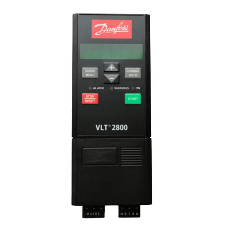
Danfoss FCM 300 Series Specification sheet

Danfoss

Danfoss FCM 300 Series Specification sheet

Danfoss VLT Midi Drive FC 280 User manual

Danfoss

Danfoss VLT Midi Drive FC 280 User manual

Danfoss VLT Guide

Danfoss

Danfoss VLT Guide

Danfoss VLT MCB 115 User manual

Danfoss

Danfoss VLT MCB 115 User manual

Danfoss VLT AutomationDrive FC 301 Operating instructions

Danfoss

Danfoss VLT AutomationDrive FC 301 Operating instructions

Danfoss VLT series User manual

Danfoss

Danfoss VLT series User manual

Danfoss vlt aqua Guide

Danfoss

Danfoss vlt aqua Guide

Danfoss 176F6636 User manual

Danfoss

Danfoss 176F6636 User manual
Danfoss FC 300 Guide

Danfoss

Danfoss FC 300 Guide

Danfoss VLT Automation Drive FC 360 Operating instructions

Danfoss

Danfoss VLT Automation Drive FC 360 Operating instructions

Danfoss VLT AutomationDrive FC 300 Operating instructions

Danfoss

Danfoss VLT AutomationDrive FC 300 Operating instructions

Danfoss VLT 5000 Series Instruction manual

Danfoss

Danfoss VLT 5000 Series Instruction manual

Danfoss VLT HVAC Basic Drive FC 101 User manual

Danfoss

Danfoss VLT HVAC Basic Drive FC 101 User manual

Danfoss VLT AHF 005 Guide

Danfoss

Danfoss VLT AHF 005 Guide

Danfoss VLT FC 300 User manual

Danfoss

Danfoss VLT FC 300 User manual

Danfoss FC 300 Guide

Danfoss

Danfoss FC 300 Guide

Danfoss VLT HVAC Drive FC 102 User manual
Danfoss

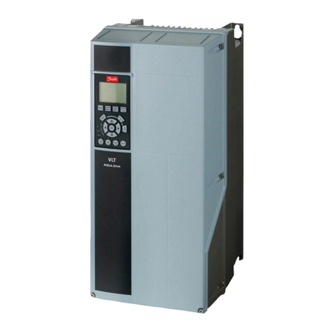
Danfoss VLT HVAC Drive FC 102 User manual

Danfoss ADAP-KOOL AKD 102 User manual

Danfoss

Danfoss ADAP-KOOL AKD 102 User manual

Danfoss VLT CDS 303 User manual

Danfoss

Danfoss VLT CDS 303 User manual

Danfoss VACON 20 X User manual

Danfoss

Danfoss VACON 20 X User manual

Danfoss FC 301 User manual

Danfoss

Danfoss FC 301 User manual

Danfoss VLT Midi Drive FC 280 Guide

Danfoss

Danfoss VLT Midi Drive FC 280 Guide

Danfoss VLT AQUA Drive FC 202 User manual

Danfoss

Danfoss VLT AQUA Drive FC 202 User manual

Danfoss vlt fcd 302 User manual

Danfoss

Danfoss vlt fcd 302 User manual

Popular DC Drive manuals by other brands

National Instruments NI MID-7604 user guide

National Instruments

National Instruments NI MID-7604 user guide

SOMFY Maestria WT Series instructions

SOMFY

SOMFY Maestria WT Series instructions

Trane TR150 Service manual

Trane

Trane TR150 Service manual

Chamberlain Garog D Series operating manual

Chamberlain Garog

Chamberlain Garog D Series operating manual

Parker PDS Series user guide

Parker

Parker PDS Series user guide

Binks QS-5012-1-CE Service manual

Binks

Binks QS-5012-1-CE Service manual

YASKAWA CANopen SI-S3 Technical manual

YASKAWA

YASKAWA CANopen SI-S3 Technical manual

GE D20A6 instructions

GE

GE D20A6 instructions

Lenze PositionServo 940 user manual

Lenze

Lenze PositionServo 940 user manual

Unex MC-D-250-1000-050W-TW operating manual

Unex

Unex MC-D-250-1000-050W-TW operating manual

Geckodrive G213V manual

Geckodrive

Geckodrive G213V manual

ABB RSYC-01 user manual

ABB

ABB RSYC-01 user manual

Rockwell Automation PowerFlex 700S Programming manual

Rockwell Automation

Rockwell Automation PowerFlex 700S Programming manual

WEG DeviceNet CFW500 user manual

WEG

WEG DeviceNet CFW500 user manual

Siemens SINAMICS G List manual

Siemens

Siemens SINAMICS G List manual

Siemens SINAMICS SM150 6SL3815-7NP41-0AA1 Operating instructions & installation instructions

Siemens

Siemens SINAMICS SM150 6SL3815-7NP41-0AA1 Operating instructions & installation instructions

SOMFY JR RU 30 instructions

SOMFY

SOMFY JR RU 30 instructions

Beckhoff AX8911 Documentation

Beckhoff

Beckhoff AX8911 Documentation

manuals.online logo
manuals.online logoBrands
  • About & Mission
  • Contact us
  • Privacy Policy
  • Terms and Conditions

Copyright 2025 Manuals.Online. All Rights Reserved.

Vacon 20 X - Simple operator panel vacon • 1
Service support: find your nearest Vacon service center at www.vacon.com 1
1. VACON 20 X - SIMPLE OPERATOR PANEL
1.1 Mounting instructions
Document code: DPD01577A
1.1.1 QDSH Simple operator panel kit
Figure 1. The Simple operator panel option spare kit (MU2 example) .
Frame
size Description and type code Item Quantity
MU2 MU2 QDSH option spare kit
60S01208
Main switch 40A NLT40 and operator
panel assembly 1
MU2 cover for main switch 1
M4x14 screw 2
M5x23 screws 4
MU3 MU3 QDSH option spare kit
60S01209
Main switch 40A NLT40 and operator
panel assembly 1
MU3 cover for main switch 1
M4x14 screw 2
M5x23 screws 6
Table 1. Simple operator panel kit content.
1
vacon • 2 Vacon 20 X - Simple operator panel
1.1.2 Installation
Figure 2. Cover open.
1• Remove the cover from the drive. See the Figure 2.
2• Open only the inlet holes where you need to run the cables. Cables pass
through this inlet hole.
3• Connect the supply cable to the Mains switch passing through the cable gland
from the bottom side (use the cable gland for sealing the cable to the drive)
and then through the terminal box as shown in the figure below.
4• Place the Simple Operator panel assembly with the cables inside the drive and
fix it with its screws.
5• Connect the cables from the Mains switch to the line terminals. The cables
have to be connected to the terminals L1, L2 and L3.
6• Fix the cables with the cable clamp.
Vacon 20 X - Simple operator panel vacon • 3
Service support: find your nearest Vacon service center at www.vacon.com 1
Figure 3. Simple operator panel connected.
7• Connect the GROUND wire to the proper terminal (see the yellow-green cable
on Figure 3.
8• Connect the cables from the potentiometer and from the selector to the I/O
control terminals. The cables have to be connected to the I/O terminals as
shown in the Figure 3 and in the Table 2.
9• RED, BLUE and BLACK wires are signals from the potentiomenter.
10 • YELLOW, WHITE and GREY wires are signal from the selector switch.
1
vacon • 4 Vacon 20 X - Simple operator panel
Table 2. Control I/O terminal signal connections to the simple operator panel.
Standard I/O terminals
Terminal Signal
ARS485_A Serial bus, negative
BRS485_B Serial bus, positive
1+10 Vref Reference output
2AI1+ Analogue input,
voltage or current
3GND I/O signal ground
624Vout 24V aux. voltage
7DIN COM Digital inputs com-
mon
8DI1 Digital input 1
9DI2 Digital input 2
10 DI3 Digital input 3
4AI2+ Analogue input,
voltage or current
5GND I/O signal ground
13 DO1- Digital output 1 com-
mon
14 DI4 Digital input 4
15 DI5 Digital input 5
16 DI6 Digital input 6
18 AO1+ Analogue signal
(+output)
20 DO1+ Digital output 1
Function Description Wire colors Terminal
Potentiomenter
10V reference output RED wire 1
AI1+ BLUE wire 2
AI1- BLACK wire 3
Switch selector
24V auxiliary voltage YELLOW wire 6
digital input DI1 WHITE wire 8
digital input DI2 GREY wire 9
Table 3. Simple operator panel connection description.
11 • Mount the plastic cover onto the drive with its screws and the HMI cap: the
installation process has been completed.
YELLOW WIRE
WHITE WIRE
GREY WIRE
RED WIRE
BLUE WIRE
BLACK WIRE