manuals.online logo
Brands
  1. Home
  2. •
  3. Brands
  4. •
  5. Danfoss
  6. •
  7. Video Game Controllers
  8. •
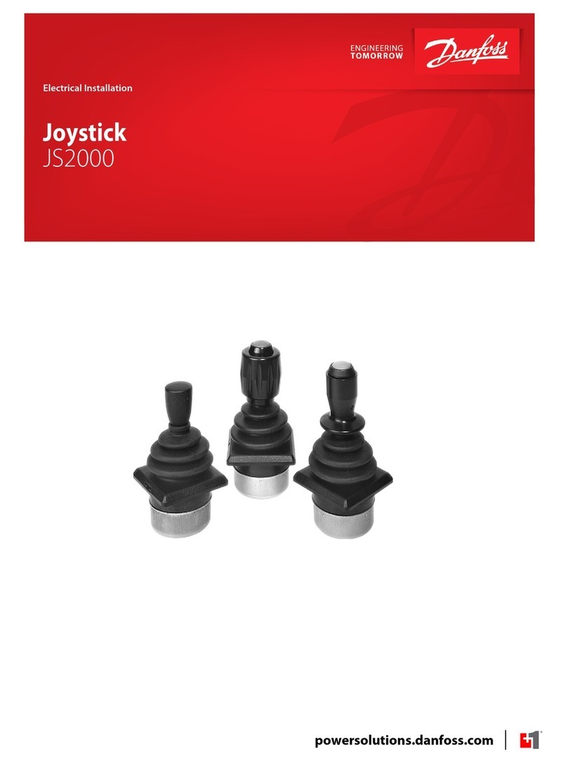
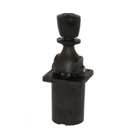
  9. Danfoss Prof 1 User manual

Danfoss Prof 1 User manual

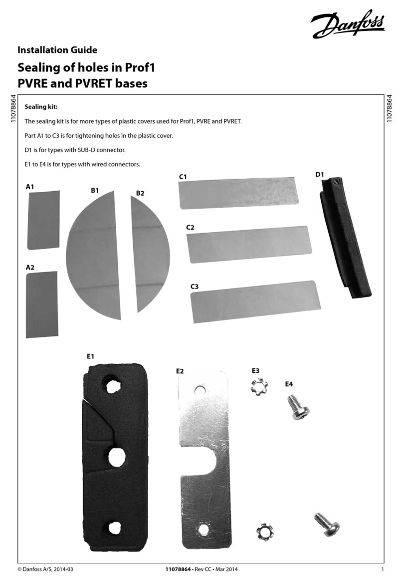
Installation Guide
Joystick Prof 1
CIP
© Danfoss, 2014-03 L1317817 • Rev AB • Mar 2014 1
162R9003
162R9003
Montering Positionering af greb
Mounting Positioning of grip
Montage Positionierung des griffes
Montage Positionnement de la poignée
H
Nøglevidde Moment
Across flats torque
Schlüsselweite Anzungsmoment
Surplats Couple de serrage
2.5 2.1 Nm
2 L1317817 • Rev AB • Mar 2014 © Danfoss, 2014-03
Terminering
Termination
Anschluß
Terminaison
Det er vigtigt at der i begge ender af CAN bussen foretages en terminering. Termineringen indeholder en 120 Ω
modstand. Denne terminering er placeret i Prof 1 CIP. For at gøre dette simpelt, er ben 1 CAN-forbundet med en
120 Ωmodstand. Derfor kan man, hvis Prof 1 CIP er den sidste CAN-komponent på bussen, terminere ved at sætte
en lus mellem CAN+ (ben 4) og CAN-Term (ben 1).
It is important to ensure termination at both ends of the CAN-bus. The termination contains a 120 Ωresistance
and is contained in Prof 1 CIP. To keep it simple, pin 16 CAN- is connected to a 120 Ωresistance. If Prof 1 CIP is the
last CAN component on the bus the termination can be ensured by incorporating a shunt between CAN+ (pin 4)
and CAN-Term (pin 1).
Es ist wichtig, daß beide Seiten vom CAN-Bus-Kabel angeschlossen sind. Dieser Anschluß umfaßt einen 120 Ω
Widerstand und ist im Prof 1 CIP enthalten. Es ist einfach Stift 16 CAN- mit einem 120 ΩWiderstand zu verbinden.
Wenn daher Prof 1 CIP die letzte CAN Komponente an dem Bus ist, kann der Bus mit diesem Widerstand
abgeschlossen werden. Verbindung mit CAN+ (Stift 4) und CAN-Term (Stift 1).
Il est important de réaliser une terminaison aux deux extrémités du CAN bus. La terminaison est constituée
d’une résistance de 120 Ωqui est incluse dans le Prof 1 CIP. La borne numéro 16 du connecteur est reliée à cette
résistance de 120 Ω. Si le Prof 1 CIP est le dernier élément du bus, il suffit d’insérer un shunt entre le CAN+ (borne
4) et le CAN_TERM (borne 1) pour connecter la résistance de terminaison.
Stikforbindelser
Plug connection
Anschlußstecker
Connexion
Stiktype
Kun del nr. 282404-1 medleveres
AMP del nr. 282404-1, hanstik
AMP del nr. 282403-1, hunstik
Tilhørende pakninger og propper
Connector type
Only part N° 282404-11 is included in the delivery
AMP part N° 282404-1, male
AMP part N° 282403-1, female
Associated seals and plugs
Steckertyp
Nur Teil Nr. 282404-1 wird mitgeliefert
AMP Teil Nr. 282404-1, Stecker
AMP Teil Nr. 282403-1, Steckbuchse
Dazugehörende Dichtungen und Stopfen
Type connecteur
Seulement livré avec élément 1282404-1
Connecteur mâle AMP N°. 282404-1
Connecteur femelle AMP N°. 282403-1
Joints et vis associées
Der er 2 stik på joysticket, og ved forbindelse er det underordnet hvilket stik der bliver forbundet.
På et stik er der følgende ben:
The joystick has two plugs, either of which can be used for connection.
Each plug offers the following pin function:
Der Joystick hat zwei Stecker, wovon jeder benytzt werden kann.
Jeder Stecker verfügt über folgende Steckerstifte:
Le manipulateur posséde 2 connecteurs identiques, que peuvent être connecteur indifféremment
Les deux connecteurs sont composés des contacts soivants:
Pin-number Description
1CAN_TERM
2Udc
3Ground
4CAN+
5CAN-
Stikforbindelser
Plug connection
Anschlußstecker
Connexion
© Danfoss, 2014-03 L1317817 • Rev AB • Mar 2014 3
Mode settings via the dip switch
Modus-Wahl mit DIP-Schalter
Réglage des sélecteurs
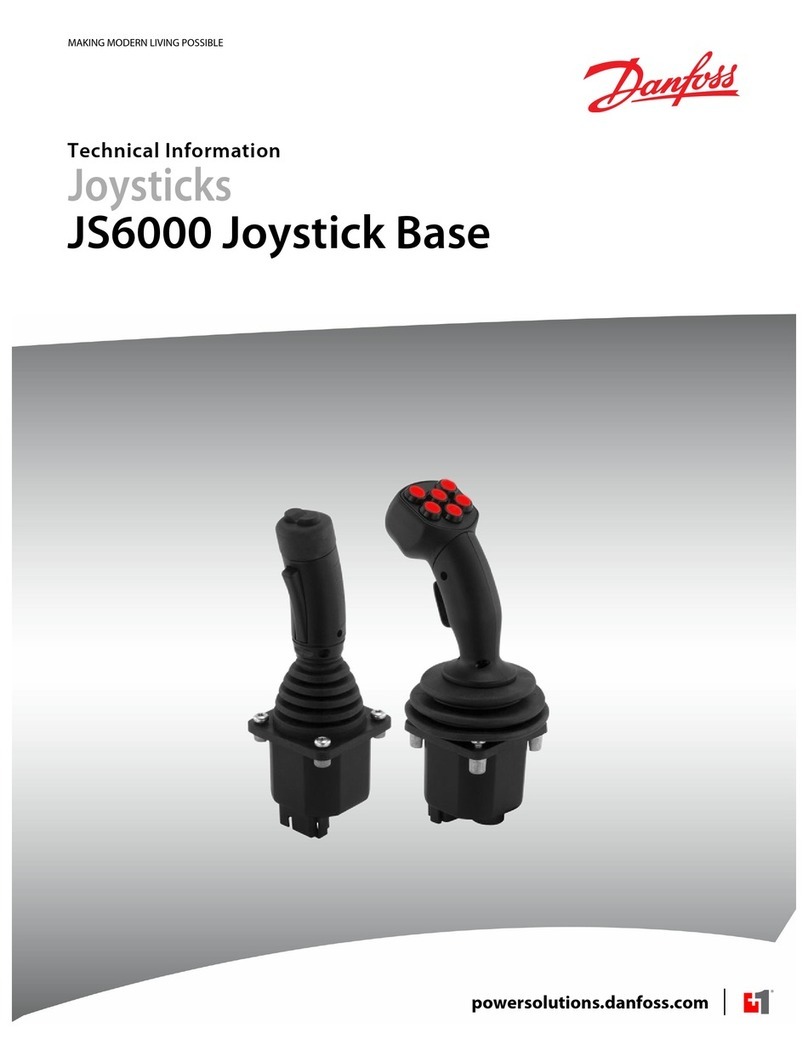
Dip switch placering
Location of the dip switch
Plazierung vom Dip-Schalter
Position des sélecteurs
Dip switch nummer
1234Mode
Closed x x x Joystick arbejder som CAN open slave
Open x x x Joystick arbejder som CAN open minimum master
xClosed x x Baudrate og Node Id som Object Dictionary og justeret via software
xOpen x x Default Baudrate og Node Id
x x Closed x -
x x Open x -
xxxClosed -
xxxOpen -
Dip switch No.
1234Mode
Closed x x x Joystick works as CAN open slave
Open x x x Joystickworks as CAN open minimum master
xClosed x x Baudrate and Node Id as per Object Dictionary and adjusted via the software
xOpen x x Default Baudrate and Node Id
x x Closed x -
x x Open x -
xxxClosed -
xxxOpen -
Dip Switch Nummer
1234Mode
Closed x x x Joystick arbeitet als CAN open Slave
Open x x x Joystick arbeitet als CAN open Minimum Master
xClosed x x Baudrate und Bus-adresse gemäß Object Dictionary und mittels der Software eingestellt
xOpen x x Standard Baudrate und Bus-adresse
x x Closed x -
x x Open x -
xxxClosed -
xxxOpen -
N° du sélecteur
1234Mode
Closed x x x Le manipulateur fonctionne en mode esclave CAN Open
Open x x x Le manipulateur fonctionne en mode maître CAN Open
xClosed x x Débit de communication et ID noeuds définis par logiciel
xOpen x x Débit de communication et numéro d’identité standard
x x Closed x -
x x Open x -
xxxClosed -
xxxOpen -
© Danfoss, 2014-03 L1317817 • Rev AB • Mar 2014 4
Strømforsyning
Forsyningsspænding Udc 10 - 30 V DC
Maks. forsyningsspænding 36 V DC
Maks. pulsation 5%
Bemærk: Prof 1 CIP kan i modsætning til analoge joystick f.eks. Prof 1 tilsluttes batteriet direkte og behøver derfor ikke at have
forsyningsspænding fra PVE’erne.
Tekniske data
Technical data
Technische Daten
Caractéristiques
Techniques
Prof 1 CIP dataformat
Prof 1 CIP data format
Prof 1 CIP Datenformat
Prof 1 CIP Format des données
SIGN = + / -
MSB = Most significant bit
LSB = Least significant bit
Power supply
Supply voltage Udc 10 - 30 V DC
Max supply voltage 36 V DC
Max ripple 5%
Note: Contrary to analogue joysticks (such as Prof 1) PROF 1 CIP can be connected direct to the battery and does not need supply
voltage directly from the PVE’s.
Stromversorgung
Versorgungsspannung Udc 10 - 30 V DC
Max Versorgungsspannung 36 V DC
Max Welligkeit 5%
Bemerkung: Im Gegensatz su analogen Joysticks (wie Prof 1) kann PROF 1 CIP direkt mit der Batterie verbunden werden und braucht
also keine Versorgungsspannung aus den PVE’s.
Alimentation
Tension d’alimentation Udc 10 - 30 V DC
Tension maximale 36 V DC
Ondulation maximale 5%
Nb: Le Prof 1 CIP peut, contrairement aus manipulateurs Prof 1 analogiques, ětre relié directement à une source d’alimentation
électrique et ne cécessite donc pas une alimentation via les PVE.
1 byte SIGN----MSB --------------------------------------------------------Prop1-----------------------------------------------------
2 byte SIGN----MSB --------------------------------------------------------Prop2-----------------------------------------------------
3 byte SIGN----MSB --------------------------------------------------------Prop3-----------------------------------------------------
4 byte SIGN----MSB --------------------------------------------------------Prop4----------------------------------------------------
5 byte rest_Prop4 - LSB rest_Prop3 - LSB rest_Prop2 - LSB rest_Prop1 - LSB
6 byte Push 8 Push 7 Push 6 Push 5 Push 4B Push 4A Push 3B Push 3A
8 bit 7 bit 6 bit 5 bit 4 bit 3 bit 2 bit 1 bit

Other Danfoss Video Game Controllers manuals

Danfoss JS2000 Series User manual

Danfoss

Danfoss JS2000 Series User manual

Danfoss JS1-H Serviceability User manual

Danfoss

Danfoss JS1-H Serviceability User manual

Danfoss JS7000 User manual

Danfoss

Danfoss JS7000 User manual

Danfoss JS6000 Manual

Danfoss

Danfoss JS6000 Manual

Danfoss PVREL User manual

Danfoss

Danfoss PVREL User manual

Danfoss JS2000 Series Manual

Danfoss

Danfoss JS2000 Series Manual

Danfoss JS6000 User manual

Danfoss

Danfoss JS6000 User manual

Danfoss JS1 series User manual

Danfoss

Danfoss JS1 series User manual

Danfoss JS120 Manual

Danfoss

Danfoss JS120 Manual

Danfoss Prof1 PVRE User manual

Danfoss

Danfoss Prof1 PVRE User manual

Popular Video Game Controllers manuals by other brands

Hama Easy Line Firejet Pro Operating	 instruction

Hama

Hama Easy Line Firejet Pro Operating instruction

GameSir T4 pro user manual

GameSir

GameSir T4 pro user manual

Wave Italy IMPACT Installation, use and maintenance manual

Wave Italy

Wave Italy IMPACT Installation, use and maintenance manual

Hama Rocket manual

Hama

Hama Rocket manual

ray allen G405 installation instructions

ray allen

ray allen G405 installation instructions

Thrustmaster Ferrari 458 Italia TX instructions

Thrustmaster

Thrustmaster Ferrari 458 Italia TX instructions

Manta MM819 user manual

Manta

Manta MM819 user manual

PowerWave NEON BLACK instructions

PowerWave

PowerWave NEON BLACK instructions

Stealth Products mo-Vis All-Round Lite Joystick owner's manual

Stealth Products

Stealth Products mo-Vis All-Round Lite Joystick owner's manual

DreamGEAR Shadow user guide

DreamGEAR

DreamGEAR Shadow user guide

Blockhead BH123 instruction manual

Blockhead

Blockhead BH123 instruction manual

Activision Guitar Hero user manual

Activision

Activision Guitar Hero user manual

Sunrise Medical Switch-It DriveStation owner's manual

Sunrise Medical

Sunrise Medical Switch-It DriveStation owner's manual

FlyDigi WASP 2 user guide

FlyDigi

FlyDigi WASP 2 user guide

Genesis P65 user manual

Genesis

Genesis P65 user manual

GamerModz PS3 Rapid Fire X-2 manual

GamerModz

GamerModz PS3 Rapid Fire X-2 manual

ACME GA-03 user manual

ACME

ACME GA-03 user manual

Thrustmaster T-WIRELESS 3-IN-1 user manual

Thrustmaster

Thrustmaster T-WIRELESS 3-IN-1 user manual

manuals.online logo
manuals.online logoBrands
  • About & Mission
  • Contact us
  • Privacy Policy
  • Terms and Conditions

Copyright 2025 Manuals.Online. All Rights Reserved.