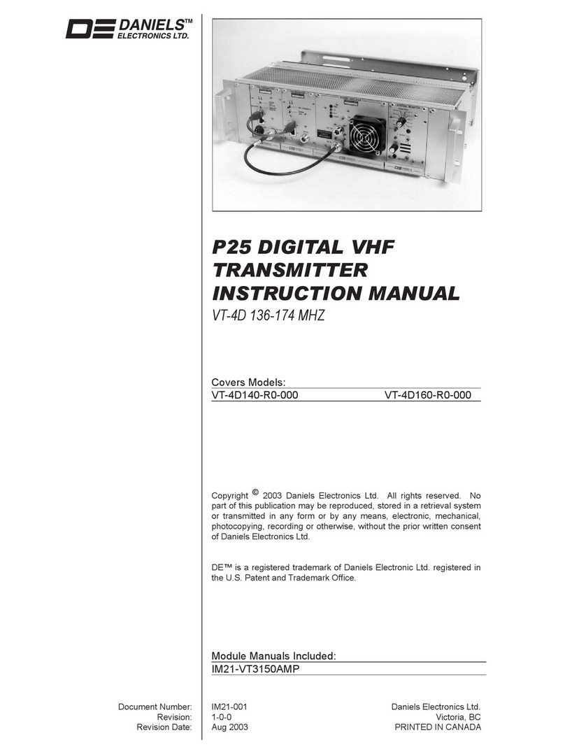
Daniels VT-4B140-00-000 User manual

MT-4
RADIO
SYSTEMS
P25 DIGITAL VHF BASE
TRANSMITTER
INSTRUCTION MANUAL
VT-4B
136 - 174 MHz
Covers models:
VT-4B140-00-000, VT-4B160-00-000
VT-4B140-01-000, VT-4B160-01-000
Copyright ©2000
Daniels
Electronics
Ltd.
All
rights reserved. No part of this
publication
may
be reproduced, stored in a
retrieval
system or
transmitted
in any form or by any means,
electronic,
mechanical,
photocopying, recording or otherwise, without the prior written consent of
Daniels
Electronics
Ltd.
DE™ is a registered trademark of Daniels Electronic Ltd. registered in the United States Patent and
Trademark Office.
Issue:
Preliminary
Previous Issue: -
Issue
Date:
July 00 Previous Issue
Date:
-
Daniels
Electronics
Ltd.
Printing
Date:
July 00
Victor
ia, BC.
Part No.:
IM21-VT4B150
PRINTED IN
CANADA

DE
DANIELS
ELECTRONICS
ii VT-4B150VHF Project25
Digital
Base
Transmitter
Instruction
Manual
Reviewed By:
Quality
Assurance:
Claudia
Boorman
_________________
Name Signature
Date
NOTE:
The
user's
authority
to
operate
this
equipment
could be revoked through any
changes or
modification
s not expressly approved by
Daniels
Electronics
Ltd.
The design of this
equipment
is subject to change due to continuous
development. This
equipment
may
incorporate
minor changes in
detail
from the
information
contained
in this manual.

DE
DANIELS
ELECTRONICS
VT-4B150VHF Project25
Digital
Base
Transmitter
Instruction
Manual
iii
TABLE OF CONTENTS
Page
1 GENERAL..................................................................................... 1-1
1.1
Introduction
.............................................................................. 1-1
1.2
Manual
Organization
.................................................................... 1-1
1.3 VT-4B136 - 174 MHz
Transmitter
Family
Models................................ 1-1
1.4
Performance
Specifications
............................................................ 1-2
1.4.1
General................................................................................ 1-2
1.4.2
Audio
Specifications
................................................................. 1-3
1.4.3
Physical
Specifications
.............................................................. 1-3
2
THEORY OF OPER
ATION
................................................................. 2-1
2.1
Transmitter
Operation
................................................................... 2-1
2.2
Transmitter
Programming.............................................................. 2-1
2.2.1
Transmitter
Wide
Options
........................................................... 2-2
2.2.1.1
Disable
FrontPanelLed.......................................................... 2-2
2.2.1.2
SecureHardwareEquipped...................................................... 2-2
2.2.1.3
Allow
Emergency
Transmissions............................................... 2-2
2.2.1.4
AllowRadio
Inhibit
............................................................... 2-2
2.2.1.5
AllowRadioCheck............................................................... 2-2
2.2.1.6
Enable
Status...................................................................... 2-2
2.2.1.7
FrequencyBand................................................................... 2-2
2.2.2
ChannelWideSettings.............................................................. 2-3
2.2.2.1
Frequency.......................................................................... 2-3
2.2.2.2
Voice/Signal
Type................................................................. 2-3
2.2.2.3
SquelchType...................................................................... 2-3
2.2.2.4
CTCSS Tone...................................................................... 2-3
2.2.2.5
Enable
ReverseBurst............................................................. 2-3
2.2.2.6
DCSCode.......................................................................... 2-3
2.2.2.7
DCSInvert......................................................................... 2-4
2.2.2.8
Enable
TurnOffCode............................................................ 2-4
2.2.2.9
Transmitter
Power ................................................................ 2-4
2.2.2.10
ChannelBandwidth............................................................. 2-4
2.2.2.11
Deviation
.......................................................................... 2-4
2.2.2.12
Time
Out
Timer
.................................................................. 2-4
2.2.2.13
ChannelStatus................................................................... 2-4
2.2.2.14
Transmitter
Pre-emphasis....................................................... 2-4
2.2.2.15
NAC
Transmitter
Code......................................................... 2-5
2.2.2.16
NAC
Transmitter
................................................................ 2-5
2.3
Transmitter
Programmingusing
Motorola
Radio ServiceSoftware .............. 2-5
2.4 Secure
Communications
................................................................ 2-6
2.5
Transmitter
Assemblyand
Adjustment
............................................... 2-6
2.5.1
Controller
Board
Alignment
........................................................ 2-6
2.5.1.1
Reference
Oscillator
Adjustment
................................................ 2-6

DE
DANIELS
ELECTRONICS
iv VT-4B150VHF Project25
Digital
Base
Transmitter
Instruction
Manual
2.5.1.2
Trans
mitter
Deviation
Balance
Adjustment
.....................................2-7
2.5.1.3
Transmitter
Deviation
Limit
Adjustment
........................................2-7
2.5.2
Amplifier
Alignment
..................................................................2-8
2.5.3
FrequencyChange....................................................................2-8
2.6
Recommended
Test
Equipment
List...................................................2-8
2.7 RepairNote...............................................................................2-9
2.8 Printed
Circuitboard
Numbering
Convention
........................................2-9
3
ILLUSTRATIONS
............................................................................3-1
3.1 MT-4Base
Transmitter
FrontPanel...................................................3-1
3.2 MT-4
Transmitter
Case-ExplodedView.............................................3-2
3.3
Digital
Base
Transmitter
Block
Diagram
..............................................3-3
3.4
Digital
Base
Transmit
ter
Schematic
Diagram
.........................................3-4
3.5
Digital
Base
Transmitter
Main
Board
Component
Layout
(Bottom)
...............3-5
3.6
Digital
Base
Transmitter
Main
Board
Component
Layout(Top)...................3-6
4 P
ARTS LIST
...................................................................................4-1
4.1 P25 Base
Transmitter
Main
BoardPartsList.........................................4-1
4.1.1
P25 Base
Transmitter
Main
Board
Electrical
PartsList..........................4-1
4.1.2
P25 Base
Transmitter
Mechanical
PartsList......................................4-3
5
REVISION HISTORY
........................................................................5-1
MODULE MANUALS
VHF Amplifier Instruction Manual VT-3 132 - 174 MHz
............
IM21-VT3150AMP

DE
DANIELS
ELECTRONICS
VT-4B150VHF Project25
Digital
Base
Transmitter
Instruction
Manual
1-1
1
GENERAL
1.1 Introduction
The VT-4B P25 Digital Base Transmitter is capable of operating in 12.5 kHz / 15 kHz or 25 kHz /
30 kHz channels. The transmitter operates continuous duty in the 136 to 174 MHz frequency band
and its output power is continuously adjustable from 2.0 to 8.0 Watts. A modular design allows
each of the transmitter's modules: Transmitter Board, VT-3/150 Amplifier to be individually
assembled and tested. This facilitates construction, tuning, maintenance as well as troubleshooting
procedures. The module can support DES-OFB decryption with a plug in module.
The VT-4B Transmitter combines state of the art performance in a compact modular enclosure for
applications ranging from remote mountain top repeaters to congested urban radio environments.
Each receiver module is characterized by dependable, low maintenance performance under the
most severe environmental conditions.
The VT-4B Transmitter is compatible with all Daniel’s subrack and base station enclosures. It
supports a basic analog interface, and may be used in a mixed system with MT-2 and MT-3 series
receivers and transmitters. It is not intended for use as a component in a digital mode repeater
system.
1.2
Manual Organization
The organization of this manual reflects the modular makeup of the VT-4 product line. Each
module is fully described within its respective submanual, all of which are contained within this
document. In general, each submanual contains:
1. A functional description and specification summary,
2. A detailed technical description (Theory of Operation) and
3. Assembly, setup and a
lignment procedures relevant to that particular module.
The module manuals are as follows.
Note: material presented in a given "sub-manual" may include information related to other module
versions not directly applicable to the VT-4 136 - 174 MHz Transmitter.
VHF Amplifier Instruction Manual VT-3 132 - 174 MHz :
The amplifier module provides the final
stages of RF power amplification and harmonic filtering for the transmitter. This manual is
intended primarily as a reference since the amplifier module is adjusted at the factory.
Radio Programming Software Instruction Manual :
This manual provides instructions on using the
PC-based Radio Programming Software package to perform transmitter alignment and frequency
and mode selection.
1.3
VT-4B 136 - 174 MHz Transmitter Family Models
There are 2 distinct models in the VT-4B Transmitter family each with different bands of
operation. The 2 models are as follows:
• VT-4B140-00-000
- 136-150 MHz band, 2.0-8.0 Watt
• VT-4B160-00-000
- 150-174 MHz band, 2.0-8.0
Watt
The transmitters' band of operation is determined by select components in the amplifier.

DE
DANIELS
ELECTRONICS
1-2 VT-4B150VHF Project25
Digital
Base
Transmitter
Instruction
Manual
1.4
Performance Specifications
1.4.1
General
The following is a general set of specifications for the generic VT-4/150 transmitter. Additional
specifications, specific to individual modules may be found in their respective sub manuals.
Type:
MT-4 Series Transmitter.
Family:
VT-4B 136 - 174 MHz.
Compatibility:
MT-2 Series and MT-3 Series Radio Systems, Project 25
interoperable.
Frequency Range:
136 to 150 MHz., 150 to 174 MHz
RF Power Output:
2.0 to 8.0 W Continuous.
Modulation:
Analog:
11K0F3E or 16K0F3E (Frequency Modulation).
Project 25:
8K10F1E
System Impedance:
50 Ω; Type N connector.
Duty Cycle:
100%; Continuous operation from -30°C to +60°C.
Emissions: -66 dBw
Transmitter Mismatch Protection:
20:1 VSWR at all phase angles.
Operating Temperature Range:
-30˚C to +60˚C
Operating Humidity:
95% RH (non-condensing) at +25°C.
Operating Voltage:
+13.8 Vdc Nominal (range +11 to +16 Vdc),
+9.5 Vdc Regulated.
Transmit Current:
1.7 Amps at 2 Watts RF Power Output,
2.8 Amps at 8 Watts RF Power Output
Front Panel Controls:
NORM (repeat mode), OFF, and KEY TX (Tx on).
PTT Activation:
• Active to ground;
• Microphone activated;
• Front Panel switch:
KEY TX;
PTT Time-Out-Timer:
Programmable from 1 sec. to 8 hrs. (default 5 min.), using
Radio Programming Software package.
Channel Spacing:
12.5 kHz /15 kHz or 25 kHz / 30 kHz.

DE
DANIELS
ELECTRONICS
VT-4B150VHF Project25
Digital
Base
Transmitter
Instruction
Manual
1-3
Frequency Stability:
Standard: ±2.5 ppm, -30°C to +60°C.
Channel Selection:
In 5.0 or 6.25 kHz increments sel
ected with Radio
Programming Software package.
Standby Current:
100 mA
DOC Type Approval:
TBA
FCC Type Acceptance:
TBA
1.4.2
Audio Specifications
Audio Input:
Unbalanced, 600 or 47k5 ohm selectable input impedance.
Audio Response:
Pre-emphasis (6 dB per octa
ve); +0.5 to -2.0 dB from 300 Hz
to 3 kHz;
Audio Deviation Limiting:
+/- 2.5 kHz, +/- 5.0 kHz
Audio Distortion:
Less than 3% THD; 1 kHz tone at 1.5 kHz or 3 kHz deviation
(-40°C to +60°C).
Hum and Noise:
-45 dB typical
1.4.3
Physical Specifications
Physical Dimensions:
Width:
Height:
Depth:
7.1 cm (2.8 in)
12.8 cm (5.05 in)
19 cm (7.5 in)
Module Weight:
1.5 kg (3.3 lbs.)
Corrosion Prevention:
Anodized aluminum construction. Stainless steel hardware.
Selectively conformal coated glass epoxy 2 and 4 layer printed
circuit boards. Gold plated module connectors.
Module Design:
Compact Eurostandard modular design. Plug-in modules
mate with Daniels standard M3 repeater subrack. Subracks /
modules comply with IEEE 1101, DIN 41494 and IEC 297-3
(mechanical size / modular arrangement).
External Connections:
RF Connection: type N connector located on the transmitter
module front panel. Motherboard Connections (Audio,
Power, and Control) are made through a 48 pin, gold plated,
type F connector on the rear of the transmitter module. User

DE
DANIELS
ELECTRONICS
1-4 VT-4B150VHF Project25
Digital
Base
Transmitter
Instruction
Manual
connection made through mated "mother board" assembly of
the repeater subrack. Type F standard connector complies
with DIN 41612 Level 2 (200 mating cycles, 4 day 10 ppm
SO2
gas test with no functional impairment and no change in
contact resistance). Digital I/O: 8-pin RJ-45
Handle Text Colour:
Red

DE
DANIELS
ELECTRONICS
VT-4B150VHF Project25
Digital
Base
Transmitter
Instruction
Manual
2-1
2
THEORY OF OPERATION
2.1
Transmitter Operation
A VT-4B Base Transmitter is constructed using two primary modules: the MT-4 Digital Base
Transmitter Main Board and the VT-4 Amplifier Board. The Main Board supports two plug in
modules: the Transmitter Controller Board and the Transmitter RF Board.
The MT-4 Digital Base Transmitter Main Board receives its audio input through the balanced input
on connector P1, from an external microphone input on connector P1, or from a front panel
microphone. Once on the Main Board, it is immediately digitized using an Analog to Digital
converter.
The digitized signal then passes to the Controller Board, where Digital Signal Processing
techniques are used for volume control, tone signalling, voice compression, filtering, and other
functions. The digital data is then converted to an analog waveform by a Digital to Analog
Converter and passed to the RF board.
On the RF board the signal is used to modulate a RF carrier and then passed to the VT-3 Amplifier
Board for final amplification and transmission.
2.2
Transmitter Programming
The transmitter is programmed with operating frequencies, modulation type, CTCSS and DCS
signalling, and other parameters with the PC-based Radio Programming Software. A special
programming cable is used to connect the serial port of an IBM compatible computer to the Digital
I/O port on the front panel of the Transmitter module. The Radio Programming Software runs
under Window 3.1, Windows 95/98 or Windows NT. Analog test modes may be selected by the
Radio Programming Software, as well as test modes specific to Project 25 digital operation, such
as Bit Error Rate testing.
*** Note that the current version of Radio Programming Software is a demonstration version
only, and cannot be used to program a Transmitter. To program a Transmitter, use Motorola’s
Radio Service Software (RSS), a Motorola Radio Interface Box (RIB), and a Daniels
Programming Cable.
The Transmitter settings are divided into two categories: Transmitter Wide options and Channel
Wide options. When the TX menu is selected from the main screen, both the Transmitter Wide
options and the Channel Wide options for the current channel are displayed. When all Transmitter
Wide and Channel Wide options have been configured in the Radio Programming Software as
required, the radio must have its non-volatile memory updated. The configuration may be saved to
the radio by selecting the TRANSMITTER \ SAVE CONFIGURATION \ TO THE RADIO menu
option. In addition, configurations may be read back from the radio, or saved and read from a file
on the computer by using the TRANSMITTER \ READ CONFIGURATION \ FROM THE
RADIO, TRANSMITTER \ READ CONFIGURATION \ FROM DISK, and TRANSMITTER \
SAVE CONFIGURATION \ TO DISK menu options.

DE
DANIELS
ELECTRONICS
2-2 VT-4B150VHF Project25
Digital
Base
Transmitter
Instruction
Manual
2.2.1
Transmitter Wide Options
Several options may be set which affect the operation of the Transmitter on a global basis.
2.2.1.1
Disable Front Panel Led
This option is not currently used. In future models it will allow the front panel led to be disabled
during normal repeater operation in order to save current.
2.2.1.2
Secure Hardware Equipped
This setting is used to allow the installation of an encryption module
2.2.1.3
Allow Emergency Transmissions
This option is not currently used.
2.2.1.4 Allow Radio Inhibit
This setting is not currently used.
2.2.1.5 Allow Radio Check
This option is not currently used. In future repeaters, this option will allow a dispatcher to query
whether the repeater is switched on or off.
2.2.1.6
Enable Status
This option is not currently used. When the option is enabled it will allow the transmitter to
transmit predetermined Status messages ("low battery", "intruder alert", for example). The Status
messages will not take precedence over user traffic.
2.2.1.7 Frequency Band
The transmitter’s frequency band is set here. The available options are 136 – 174 MHz and 406 –
470 MHz. The band from 803 – 870 MHz will become available in future models.

DE
DANIELS
ELECTRONICS
VT-4B150VHF Project25
Digital
Base
Transmitter
Instruction
Manual
2-3
2.2.2
Channel Wide Settings
There are currently 32 channels, which may be individually programmed for various parameters.
2.2.2.1 Frequency
The transmitter’s frequency may be set here. The Radio Programming Software will only allow
frequencies within the operation band (set in the Transmitter Wide options above) to be entered.
2.2.2.2
Voice/Signal Type
Allowed values are PROJECT 25, ANALOG and MIXED MODE. PROJECT 25 mode receives
digital P25 modulated signals only, while ANALOG mode receives analog FM signals only. In
MIXED MODE the transmitter will transmit either PROJECT 25 digital and analog signals,
depending on which mode of signal was received. When either ANALOG or MIXED MODE
values are selected, additional combo boxes appear to allow selection of Squelch Type for
ANALOG mode signals.
2.2.2.3
Squelch Type
This option is available for ANALOG signals only, and may be set to CSQ, CTCSS or DCS.
With the CSQ option, the transmitter will not send either a CTCSS subaudible tone or a DCS code
along with the signal being transmitted. With the CTCSS option the transmitter will send a
subaudible Continuous Tone Coded Squelch System tone along with the audio signal. Similarly,
when the DCS option is used the transmitter will transmit a Digital Controlled Squelch code with
the audio signal. When either CTCSS or DCS Squelch Type is selected, additional combo boxes
appear to allow selection of a particular tone or code.
2.2.2.4
CTCSS Tone
The frequency of the CTCSS tone may be selected here. All the thirty-nine standard frequencies
are supported, along with three non-standard frequencies.
2.2.2.5 Enable Reverse Burst
This option enables a Reverse CTCSS Burst to be sent at the end of a transmission. The Reverse
Burst signals to the receiving radio that the transmission is ending, allowing it to mute more
quickly.
2.2.2.6
DCS Code
One of eighty-six DCS codes may be selected here.

DE
DANIELS
ELECTRONICS
2-4 VT-4B150VHF Project25
Digital
Base
Transmitter
Instruction
Manual
2.2.2.7
DCS Invert
This option allows the DCS code to have its phase inverted by 180 degrees, which is used to
compensate for phase inversions introduced in the signal path.
2.2.2.8
Enable Turn Off Code
This option enables a DCS Turn Off Code to be sent at the end of a transmission. The Turn Off
Code signals to the receiving radio that the transmission is ending, allowing it to mute more
quickly.
2.2.2.9 Transmitter Power
This option is not currently used.
2.2.2.10
Channel Bandwidth
This setting should be changed to match the channel spacing and bandwidth of the operating
channel. Both 25 kHz and 12.5 kHz are supported for Analog channels, while Project 25
channels are limited to 12.5 kHz.
2.2.2.11
Deviation
This is a read-only field that shows the maximum amount that the transmitter frequency will
deviate. This field changes automatically in response to the Channel Bandwidth setting. A
bandwidth of 25 kHz selects a maximum deviation of 5 kHz, while a bandwidth of 12.5 kHz
selects a maximum deviation of 2.5 kHz.
2.2.2.12
Time Out Timer
This option enables the operation of a Time Out Timer that disables the transmitter output after a
predetermined period of use. If the option is enabled, a further box becomes visible to allow the
user to set the desired time into the timer.
2.2.2.13
Channel Status
This option is not currently used.
2.2.2.14
Transmitter Pre-emphasis
For analog channels, the standard 6 dB/octave pre-emphasis curve may be either disabled or
applied to the transmitted audio

DE
DANIELS
ELECTRONICS
VT-4B150VHF Project25
Digital
Base
Transmitter
Instruction
Manual
2-5
2.2.2.15
NAC Transmitter Code
This field allows a Network Access Code to be defined for the transmitter.
2.2.2.16
NAC Transmitter
This option is not used for the Base Transmitter.
2.3
Transmitter Programming using Motorola Radio Service Software
Daniels’ Radio Programming Software package is not yet ready to program the transmitter
module. Therefore, it is recommended that Motorola’s Radio Service Software (RSS) and Radio
Interface Box (RIB) be used in conjunction with a Daniels Radio Programming Cable to program
the transmitter modules. For instructions on how to use the RSS, consult Motorola’s Astro
Portable / Mobile Radio Software User’s Guide. The MT-4 Base receiver is programmed as if it
were an Astro Portable radio.
Some settings in the RSS must be configured correctly for the receiver module to work:
Menu Path
Setting
Value
Main:Change/View:Config:Radio Options
Secure Hardware
Equipped
Yes or no, - according to
whether or not an
encryption module is
installed in the transmitter
Main:Change/View:Config:Features:Buttons
Top Button
16 Pos Rotary
Switch
Side Button 1 (top)
Side Button 2
Side Button 3
Blank
Channel Select
Blank
Blank
Blank
Main:Change/View:Config:Radio
Options:Options
Time Out Timer
Table
Set up to four different
transmitter time values,
which are then selected by
each personality.
Main:Change/View:Config:Features:Switches
Two Position
Concentric (A/B)
Position A
Position B
Concentric Rocker
Switch
Position 1
Position 2
Zone Select
Zone Select
Clear TX Select
Secure TX Select
Main:Change/View:Zone/Chan
Assign personalities to
channels. Each of Zone 1
and 2 must have at least
one channel assigned.
Main:Change/View:Conv:MDC:Systems
Emergency
Disabled
Main:Change/View:Conv:Astro:Systems
Emergency
Disabled
Main:Change/View:Conv:Pers:Options:Options
TX Network ID
(set this for each
personality)
Set to desired NAC code
(293 is default value)

DE
DANIELS
ELECTRONICS
2-6 VT-4B150VHF Project25
Digital
Base
Transmitter
Instruction
Manual
2.4
Secure Communications
The transmitter is capable of sending secure communications if a DES-OFB encryption module is
installed. To transmit a secure signal, the transmitter must be programmed with the correct
encryption key using a Motorola KVL keyloader in conjunction with a Daniels Keyloader Cable.
Consult the instructions for the Keyloader for details on loading a key. A loaded key may be
cleared by pulling first the CLEAR KEYS 1* then the CLEAR KEYS 2* inputs to ground about
500 ms apart. Alternately, the PAC-4 controller may be used to clear the keys from all modules in
a system with a single keypress.
2.5
Transmitter Assembly and Adjustment
All modules are mounted on the Transmitter Main Board that then forms a single assembly. An
extruded aluminum shell that slides over the Transmitter Main Board as illustrated in section 3.2)
forms an enclosure. This shell also serves as a heat sink to remove heat from the Amplifier module
and for this reason, it is important that the four screws that bond the shell to the amplifier module
(Screws B in Section (3-2)) be installed before prolonged operation of the transmitter. Moreover,
the surface of the Amplifier module that contacts the shell should be clean and free of foreign
material. The enclosure is completed by the installation of front and rear plates, which are fastened
to the Transmitter Main Board.
Transmitter alignment is performed on a module by module basis and detailed steps are provided in
the respective manuals. Alignment is simplified by using an SR-3 Sub rack, SM-3 System
Monitor, and RF extender cable to provide transmitter power and signal interconnection.
Alternatively, +9.5 Vdc and +13.8 Vdc, as well as any required test signals, may be applied
directly to the individual modules. Refer to the corresponding manuals for details.
2.5.1
Controller Board Alignment
A Controller Board Alignment is performed at the factory and should not be required under normal
circumstances. A large change in operating frequency, as discussed in the next section, or
replacement of RF or Controller Boards may require a complete realignment operation. The Radio
Programming Software and Programming Cable must be used to access these tuning modes. This
operation requires that the transmitter module and amplifier be separately aligned in the following
order.
Sequence
Module
Manual Reference
(1)
Transmitter Main Board
Section 2.3 of this manual,
(2)
Amplifier
Amplifier Manual
2.5.1.1
Reference Oscillator Adjustment
The reference oscillator provides an accurate frequency standard to which the transmitter's carrier
signal is phase locked. To adjust the reference oscillator frequency, disconnect the RF Board from
the amplifier module by separating the SMB connectors. For this test, the RF board will generate
a 0 dBm RF signal from its RF output. Connect the RF output cable of the RF board to a
frequency counter or communications test set. Connect the transmitter to an IBM compatible
computer using the Programming Cable. Apply power to the transmitter and run the Radio
Programming Software. Navigate to the TRANSMITTER \ SERVICE \ REFERENCE
OSCILLATOR menu, where you will see a test frequency displayed and a slider to adjust the
frequency. Click on the "ENABLE TX" button and move the slider until the frequency measured

DE
DANIELS
ELECTRONICS
VT-4B150VHF Project25
Digital
Base
Transmitter
Instruction
Manual
2-7
by the frequency counter matches the test frequency displayed on the screen to within +/- 150 Hz.
Click on the "UPDATE SOFTPOT" button to save the setting in the transmitter's non-volatile
memory. This completes the adjustment of the reference oscillator. Leave the RF Board
disconnected from the amplifier module and continue with the next alignment procedure.
2.5.1.2
Transmitter Deviation Balance Adjustment
This adjustment equalizes the modulation sensitivity of the low and high frequency modulation
paths on the RF board. To perform the adjustment, disconnect the RF Board from the amplifier
module by separating the SMB connectors. Connect the RF output cable of the RF board to a
communications test set. Connect the transmitter to an IBM compatible computer using the
Programming Cable. Apply power to the transmitter and run the Radio Programming Software.
Navigate to the TRANSMITTER \ SERVICE TRANSMITTER \ DEVIATION BALANCE screen,
where you will see a list of test frequencies and current SoftPot values for each frequency.
YSelect the radio button next to the first test frequency and click on the "LOW PTT" button. This
causes an internally generated 80 Hz tone to be applied to the modulator. Note the deviation of the
carrier on the communications test set, and click on the "HIGH PTT" button. This causes a 3 kHz
tone to be applied to the modulator. Adjust the slider next to the test frequency until the measured
deviation matches that of the 80 Hz tone. Now click on the "LOW PTT" button again to check the
deviation. If the deviation has changed from the original reading, note the new deviation and
perform the adjustment at the high frequency again. It may require several iterations of this
process to get the deviations to match within +/- 2%. When the deviations match, click on the
"UPDATE SOFTPOT" button to save the setting in the transmitter's non-volatile memory.
YRepeat the adjustment process for each of the test frequencies. Leave the RF Board disconnected
from the amplifier module and continue with the next alignment procedure.
2.5.1.3
Transmitter Deviation Limit Adjustment
This adjustment prevents over-deviation of the transmitter's carrier. To perform the adjustment,
disconnect the RF Board from the amplifier module by separating the SMB connectors. Connect
the RF output cable of the RF board to a communications test set. Connect the transmitter to an
IBM compatible computer using the Programming Cable. Apply power to the transmitter and run
the Radio Programming Software. Navigate to the TRANSMITTER \ SERVICE
TRANSMITTER \ ADJUST DEVIATION LIMITS menu item, where you will see a list of test
frequencies and current SoftPot values for each frequency. Select the radio button next to the first
test frequency and click on the "ENABLE TX" button to key the transmitter. Adjust the slider next
to the selected test frequency under the measured deviation of the carrier is between 2785 Hz and
2885 Hz. Click on the "UPDATE SOFTPOT" button to save the new setting to the radio's non-
volatile memory. Repeat the process for each test frequency. This completes the adjustment
process for the transmitter deviation limits, and completes the alignment process for the Main
Board.

DE
DANIELS
ELECTRONICS
2-8 VT-4B150VHF Project25
Digital
Base
Transmitter
Instruction
Manual
2.5.2
Amplifier Alignment
The RF power output of the amplifier is set to its rated value of 2.0 Watts or 8.0 Watts at the
factory. This should not require adjustment under normal circumstances. However, should it be
necessary to correct the output power, follow the procedure in the Amplifier Manual. Adjustment
may also be required when the transmitter's operating frequency is changed. When a large
frequency change has been programmed into the transmitter, the amplifier should be aligned at the
new frequency according to the Amplifier Manual.
2.5.3
Frequency Change
The transmitter is initially aligned at the factory for the frequency stamped on the 'Factory Set
Operating Frequency' label (see section 3.1). This label should list the frequency at which the last
complete transmitter alignment was performed. For a small frequency change, a simple channel
change (see section 2.2) may be all that is required. A larger frequency change may involve the
realignment of other modules. The frequency change in question is the
accumulated frequency
change
in relation to the frequency stamped on the label. For example, if the frequency were
changed by 0.5 MHz from that stamped on the label, then a second frequency change of 1 MHz in
the same direction would result in a total change of 1.5 MHz. The action taken would be on the
basis of the 1.5 MHz value. Failure to perform a realignment after a large frequency change could
result in unreliable transmitter operation or transmitter operation that does not conform to the
published specifications. The allowable frequency change is summarized below.
Note:
It is advisable to confirm these frequency ranges with the Amplifier, as they are subject to
change with updated versions. The values in the module manuals take precedent over
those tabulated (following page).
Size of Frequency Change
Modules to be Aligned
less than ± 1 MHz
no alignment required, check output power
greater than ± 1 MHz
Transmitter Power Amplifier
2.6 Recommended Test Equipment List
Alignment of the transmitter requires the following test equipment or its equivalent.
Dual
Power Supply:
Regulated
+9.5
Vdcat 2 A.
Regulated
+13.8
Vdcat 2 A - Topward TPS-4000
Oscilloscope
/
Multimeter:
Fluke 97
Scopemeter
Current
Meter:
Fluke 75
multimeter
Radio
communications
test set :
Marconi
Instruments 2955R (analog only)
Motorola
R2670 with Project25 option
Alignment
Tool:
Johanson 4192
It is recommended that the radio communications test set be frequency locked to an external
reference (WWVH, GPS, Loran C) so that the high stability oscillator may be accurately set to
within its ±1 ppm frequency tolerance.

DE
DANIELS
ELECTRONICS
VT-4B150VHF Project25
Digital
Base
Transmitter
Instruction
Manual
2-9
2.7 Repair Note
The transmitter is mainly made up of surface mount devices that should not be removed or replaced
using an ordinary soldering iron. Removal and replacement of surface mount components should
be performed only with specifically designed surface mount rework and repair stations complete
with ElectroStatic Discharge (ESD) protection.
When removing Surface Mount Solder Jumpers, it is recommended to use solder braid in place of
manual vacuum type desoldering tools when removing jumpers. This will help prevent damage to
the circuit boards.
2.8
Printed Circuitboard Numbering Convention
To ease troubleshooting and maintenance procedures, Daniels Electronics Limited has adopted a
printed circuitboard (PCB) numbering convention in which the last two digits of the circuitboard
number represent the circuitboard version. For example:
• PCB number 43-9120
10
indicates circuitboard version 1.0;
• PCB number 50002-
02
indicates circuitboard version 2.0.
All PCB's manufactured by Daniels Electronics are identified by one of the above conventions.

DE
DANIELS
ELECTRONICS
2-10 VT-4B150VHF Project25
Digital
Base
Transmitter
Instruction
Manual
This Page Intentionally Left Blank

ELECTRONICS
DANIELS
3-1P25 Digital Base Transmitter Instruction Manual
3 ILLUSTRATIONS
3.1 Digital Base Transmitter Front Panel
P25 BASE TX
TRANSMITTER
MODEL IDENTIFIER
ON / OFF / KEY SWITCH
TYPE N RF
INPUT JACK
RJ45 CONNECTOR
FACTORY SET
OPERATING
FREQUENCY
MADE IN CANADA
VT-4B150
B
TRANSMIT
LED
POWER LED
165.0000
PROG
BUS
A
B
MIC
RF OUT
TX
PWR
OFF
KEY TX
NORM
FREQUENCY (MHz)
MADE IN CANADA
TM
xT4DBM1

3 FINGER GASKET (2)
Transmitter Case Removal:
1. Remove Screws A (four M3x8mm).
2. Remove Screws B (four M5x8mm).
3. Hold Front Panel and Pull Case.
A
A
A
A
B
B
B
B
ELECTRONICS
DANIELS
P25 Digital Base Transmitter Instruction Manual
xT4DBM2
3-2
3.2 Digital Base Transmitter Case - Exploded View
This manual suits for next models
3
Table of contents
Other Daniels Transmitter manuals