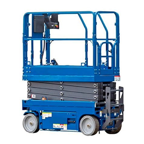
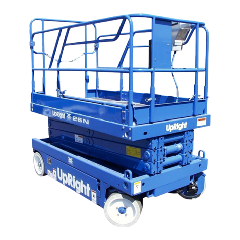
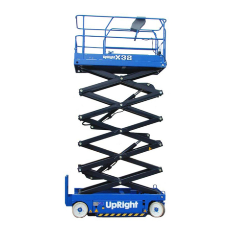
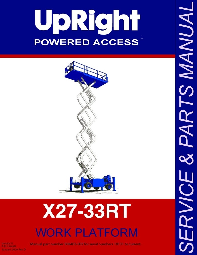
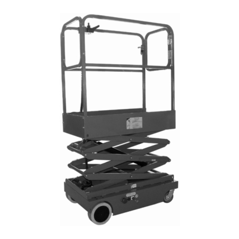
Upright X26N Guide

POWERED ACCESS
WORK PLATFORM
X26N
SERVICE & PARTS MANUAL
508244-005
sn : 5119+ Feb10


X26 Narrow
English
When contacting UpRight for service or parts information, be sure to include the MODEL and SERIAL
NUMBER from the equipment Nameplate.
Should the nameplate be missing, the SERIAL NUMBER is also stamped on top of the chassis above the
front axle pivot.
Stamped
Serial Number
Upright Nameplate is fitted to rear
of Chassis.


Page i
FOREWORD
HOW TO USE THIS MANUAL
This manual is divided into six sections.
SECTION 1 INTRODUCTION
General description and machine specifications.
SECTION 2 OPERATION AND SPECIFICATION
Information on how to operate the work platform and how to prepare it for operation.
SECTION 3 MAINTENANCE
Preventative maintenance and service information.
SECTION 4 TROUBLESHOOTING
Causes and solutions to typical problems.
SECTION 5 SCHEMATICS
Schematics and valve block diagram with description and location of components.
SECTION 6 ILLUSTRATED PARTS BREAKDOWN
Complete parts lists with illustrations.
SPECIAL INFORMATION
NOTE: Gives helpful information.
DANGER
! !
Indicates an imminently hazardous situation which, if not avoided, will result
in death or serious injury.
WARNING
!!
Indicates a potentially hazardous situation which, if not avoided, could result
in death or serious injury.
CAUTION
!!
Indicates a potentially hazardous situation which, if not avoided, may result
in minor or moderate injury.

Page ii
Foreword -
WORKSHOP PROCEDURES
All information contained in this manual is based on the latest product information available at
the time of printing. We reserve the right to make changes at any time without notice.
No part of this publication may be reproduced, stored in retrieval system, or transmitted, in any
form by any means, electronic, mechanical, photocopying, recording, or otherwise, without the
prior written permission of the publisher. This includes text, figures and tables.
CAUTION
!!
Detailed descriptions of standard workshop procedures, safety principles
and service operations are not included.
Please note that this manual does contain warnings and cautions against
some specific service methods which could cause personal injury or could
damage a machine or make it unsafe.
Please understand that these warnings cannot cover all conceivable ways in
which service, whether or not recommended by UpRight, might be done, or
of the possible hazardous consequences of each conceivable way, nor could
UpRight, investigate all such ways.
Anyone using service procedures or tools, whether or not recommended by
UpRight, must satisfy themselves thoroughly that neither personal safety
nor machine safety will be jeopardized.

Page 1-1
Section 1
INTRODUCTION
1.1 INTRODUCTION
PURPOSE
The purpose of this service and parts manual is to provide instructions and illustrations for the
operation and maintenance of this work platform manufactured by UpRight.
SCOPE
The manual includes procedures for proper operation, maintenance, adjustment, and repair of
this product as well as recommended maintenance schedules and troubleshooting.
1.2 GENERAL DESCRIPTION
The work platform consists of the platform, controller, elevating assembly, power module, control
module, and chassis.
Figure 1-1: X26N
PLATFORM
The platform has a reinforced steel
floor, 1.1m (43.5 inch) high guardrails
with midrail, 152 mm (6 inch )
toeboards, and an entry chain at the
rear of the platform. The guardrails
can be folded down for access
through doors or for shipment.
PLATFORM CONTROLLER
The platform controller contains the
controls to operate the machine. It is
located at the front of the platform
cage. A complete explanation of
control functions can be found in
Section 2.
WARNING
!!
DO NOT use the work platform without guardrails properly assembled and in
place.
1.Platform
2.PlatformController
Assembly
3.Chassis Controls
4.Chassis
5.Elevating Assembly
1
3
4
2
5

Page 1-2
Introduction 1.2 - General Description
ELEVATING ASSEMBLY
The platform is raised and lowered by the elevating assembly. The hydraulic pump, driven by the
engine, powers the cylinder. Solenoid operated valves control raising and lowering.
CHASSIS
The chassis is a structural frame that supports all the components of the X26N work platform.
PURPOSE OF EQUIPMENT
The objective of the work platform is to provide a quickly deployable, self-propelled, variable
height work platform to elevate personnel and materials to overhead work areas.
SPECIAL LIMITATIONS
Travel with the platform raised is limited to a creep speed range.
Elevating of the work platform is limited to firm, level surfaces only.
DANGER
! !
The elevating function shall ONLY be used when the work platform is level
and on a firm surface.
The work platform is NOT intended to be driven over uneven, rough, or soft
terrain when elevated.

Page 1
WARNING
Allpersonnelshallcarefullyread,understand and followall safetyrulesand operatinginstructions
beforeoperatingorperforming maintenance onany UpRight PoweredAccessworkplatform.
USEOFTHE AERIAL WORK PLATFORM:Thisaerial workplatformisintended to liftpersonsand histools as
well asthe materialused for the job. It isdesigned for repair and assemblyjobsandassignmentsat overhead
workplaces(ceilings, cranes, buildingsetc) All other usesof the aerialworkplatformareprohibited!
THIS AERIALWORK PLATFORMIS NOTINSULATED! Forthis reasonit isimperative tokeepasafedistancefromlive
partsof electrical equipment!
Exceedingthespecified permissiblemaximum load isprohibited! See“PlatformCapacity”onpage5for details.
Theuse andoperationoftheaerial workplatformas aliftingtool oracrane isprohibited!
This machineis designed forINDOORUSE ONLY!
DISTRIBUTE all platform loads evenly ontheplatform.
NEVER operatethemachinewithout firstsurveyingthe workareafor surfacehazards.
Holes, drop-offs, bumps, curbs,anddebris etc.should ALWAYS be AVOIDED!
OPERATE machineonly on surfacescapable of supporting wheel loads.
IN CASE OF EMERGENCY pushEmergencyStop Switchtodeactivateall poweredfunctions.
IFALARMSOUNDS whileplatformis elevated,STOP, carefully lowerplatform. Movemachinetoafirm,levelsurface.
Climbingup the railingoftheplatform, standing onorsteppingfromtheplatformontobuildings, steel orprefabconcrete
structures, etc., isprohibited!
Dismantlingtheentrygateorotherrailingcomponents isprohibited! Always makecertainthattheentrygateisclosedand
securely locked!
It isprohibited tokeep the entrygateinan openpositionwhen the platform is raised!
To extendtheheight ortherange byplacingof ladders, scaffoldsorsimilardevicesonthe platform isprohibited!
NEVER performserviceonmachine while platformis elevatedwithout blockingelevatingassembly.
INSPECT themachinethoroughly forcrackedwelds,looseormissinghardware,hydraulic leaks, loosewire connections,
and damagedcablesor hoses beforeusing.
VERIFY that all labels arein placeandlegiblebeforeusing.
NEVER useamachinethat is damaged,not functioningproperly,or has damaged or missinglabels.
To bypass any safetyequipment isprohibited and presents adangerforthepersonson theaerialwork platformandinits
working range.
NEVER charge batteries nearsparks oropen flame. Charging batteriesemitexplosivehydrogen gas.
Modificationstotheaerial work platform areprohibited orpermissibleonly at theapproval byUpRight.
AFTER USE,securethe workplatform fromunauthorizedusebyturningtheKeyswitchOFFand removingkey.
NEVER operate the boom or drive
with the platform elevated unless
on firm, levelsurface.
NEVER position the machine
without firstchecking for overhead
obstructionsorother hazards.
NEVER climb, stand orsit on the
platform guardrailsormidrail.
Electrocution Hazard TipOverHazard CollisionHazard FallHazard
THIS MACHINEIS NOT
INSULATED!

Page 2
C
ONTENTS
P
AGE
1. Introduction . . . . . . . . . . . . . . . . . . . . . . . . . . . . . . . . . . . . . . . . . . . . . . . . . . . . . . . . . . . . . . . . . . . . . . . .3
Special Information. . . . . . . . . . . . . . . . . . . . . . . . . . . . . . . . . . . . . . . . . . . . . . . . . . . . . . . . . . . . . . . . . . . . 3
2. General Description . . . . . . . . . . . . . . . . . . . . . . . . . . . . . . . . . . . . . . . . . . . . . . . . . . . . . . . . . . . . . . . . .4
3. Special Limitations . . . . . . . . . . . . . . . . . . . . . . . . . . . . . . . . . . . . . . . . . . . . . . . . . . . . . . . . . . . . . . . . . .5
Platform Capacity . . . . . . . . . . . . . . . . . . . . . . . . . . . . . . . . . . . . . . . . . . . . . . . . . . . . . . . . . . . . . . . . . . . . 5
Manual Force . . . . . . . . . . . . . . . . . . . . . . . . . . . . . . . . . . . . . . . . . . . . . . . . . . . . . . . . . . . . . . . . . . . . . . . 5
Lift Overload Alarm . . . . . . . . . . . . . . . . . . . . . . . . . . . . . . . . . . . . . . . . . . . . . . . . . . . . . . . . . . . . . . . . . . . 5
4. Controls and Indicators . . . . . . . . . . . . . . . . . . . . . . . . . . . . . . . . . . . . . . . . . . . . . . . . . . . . . . . . . . . . . .6
5. Pre-Operation Safety Inspection . . . . . . . . . . . . . . . . . . . . . . . . . . . . . . . . . . . . . . . . . . . . . . . . . . . . . . .7
6. System Function Inspection . . . . . . . . . . . . . . . . . . . . . . . . . . . . . . . . . . . . . . . . . . . . . . . . . . . . . . . . . .8
6. Operation . . . . . . . . . . . . . . . . . . . . . . . . . . . . . . . . . . . . . . . . . . . . . . . . . . . . . . . . . . . . . . . . . . . . . . . . . .9
Platform Extension . . . . . . . . . . . . . . . . . . . . . . . . . . . . . . . . . . . . . . . . . . . . . . . . . . . . . . . . . . . . . . . . . . . 9
Travel With the Platform Lowered. . . . . . . . . . . . . . . . . . . . . . . . . . . . . . . . . . . . . . . . . . . . . . . . . . . . . . . . . 9
Steering. . . . . . . . . . . . . . . . . . . . . . . . . . . . . . . . . . . . . . . . . . . . . . . . . . . . . . . . . . . . . . . . . . . . . . . . . . . . . 9
Elevating the Platform. . . . . . . . . . . . . . . . . . . . . . . . . . . . . . . . . . . . . . . . . . . . . . . . . . . . . . . . . . . . . . . . . 10
Travel with Work Platform Elevated . . . . . . . . . . . . . . . . . . . . . . . . . . . . . . . . . . . . . . . . . . . . . . . . . . . . . 10
Lowering the Platform . . . . . . . . . . . . . . . . . . . . . . . . . . . . . . . . . . . . . . . . . . . . . . . . . . . . . . . . . . . . . . . . 10
Emergency Lowering . . . . . . . . . . . . . . . . . . . . . . . . . . . . . . . . . . . . . . . . . . . . . . . . . . . . . . . . . . . . . . . . 10
Guardrails . . . . . . . . . . . . . . . . . . . . . . . . . . . . . . . . . . . . . . . . . . . . . . . . . . . . . . . . . . . . . . . . . . . . . . . . . 11
Lowering Procedure. . . . . . . . . . . . . . . . . . . . . . . . . . . . . . . . . . . . . . . . . . . . . . . . . . . . . . . . . . . . 11
Raising Procedure . . . . . . . . . . . . . . . . . . . . . . . . . . . . . . . . . . . . . . . . . . . . . . . . . . . . . . . . . . . . . 11
Parking Brake Release . . . . . . . . . . . . . . . . . . . . . . . . . . . . . . . . . . . . . . . . . . . . . . . . . . . . . . . . . . . . . . . 12
Release the Parking Brake . . . . . . . . . . . . . . . . . . . . . . . . . . . . . . . . . . . . . . . . . . . . . . . . . . . . . . 12
Engage the Parking Brake. . . . . . . . . . . . . . . . . . . . . . . . . . . . . . . . . . . . . . . . . . . . . . . . . . . . . . . 12
After Use Each Day. . . . . . . . . . . . . . . . . . . . . . . . . . . . . . . . . . . . . . . . . . . . . . . . . . . . . . . . . . . . . . . . . . 12
8. Transporting the Machine . . . . . . . . . . . . . . . . . . . . . . . . . . . . . . . . . . . . . . . . . . . . . . . . . . . . . . . . . . .13
Lifting By Crane. . . . . . . . . . . . . . . . . . . . . . . . . . . . . . . . . . . . . . . . . . . . . . . . . . . . . . . . . . . . . . . . . . . . . 13
Moving By Forklift . . . . . . . . . . . . . . . . . . . . . . . . . . . . . . . . . . . . . . . . . . . . . . . . . . . . . . . . . . . . . . . . . . . 13
Driving or Winching onto a Truck or Trailer. . . . . . . . . . . . . . . . . . . . . . . . . . . . . . . . . . . . . . . . . . . . . . . . 14
9. Maintenance . . . . . . . . . . . . . . . . . . . . . . . . . . . . . . . . . . . . . . . . . . . . . . . . . . . . . . . . . . . . . . . . . . . . . .15
Blocking The Elevating Assembly . . . . . . . . . . . . . . . . . . . . . . . . . . . . . . . . . . . . . . . . . . . . . . . . . . . . . . 15
Scissor Brace Installation . . . . . . . . . . . . . . . . . . . . . . . . . . . . . . . . . . . . . . . . . . . . . . . . . . . . . . . 15
Scissor Brace Storage. . . . . . . . . . . . . . . . . . . . . . . . . . . . . . . . . . . . . . . . . . . . . . . . . . . . . . . . . . 15
Level Sensor. . . . . . . . . . . . . . . . . . . . . . . . . . . . . . . . . . . . . . . . . . . . . . . . . . . . . . . . . . . . . . . . . . . . . . . 16
Testing the Level Sensor . . . . . . . . . . . . . . . . . . . . . . . . . . . . . . . . . . . . . . . . . . . . . . . . . . . . . . . . 16
Hydraulic Fluid . . . . . . . . . . . . . . . . . . . . . . . . . . . . . . . . . . . . . . . . . . . . . . . . . . . . . . . . . . . . . . . . . . . . . 17
Check Hydraulic Fluid . . . . . . . . . . . . . . . . . . . . . . . . . . . . . . . . . . . . . . . . . . . . . . . . . . . . . . . . . . 17
Battery Maintenance. . . . . . . . . . . . . . . . . . . . . . . . . . . . . . . . . . . . . . . . . . . . . . . . . . . . . . . . . . . . . . . . . 17
Battery Charging. . . . . . . . . . . . . . . . . . . . . . . . . . . . . . . . . . . . . . . . . . . . . . . . . . . . . . . . . . . . . . . . . . . . 17
Daily Inspection and Maintenance Schedule . . . . . . . . . . . . . . . . . . . . . . . . . . . . . . . . . . . . . . . . . . . . . .18
Daily Preventative Maintenance Check List . . . . . . . . . . . . . . . . . . . . . . . . . . . . . . . . . . . . . . . . . . . . . . . 18
Maintenance Table Key . . . . . . . . . . . . . . . . . . . . . . . . . . . . . . . . . . . . . . . . . . . . . . . . . . . . . . . . . 18
Maintenance Report. . . . . . . . . . . . . . . . . . . . . . . . . . . . . . . . . . . . . . . . . . . . . . . . . . . . . . . . . . . . 18
11. Labels . . . . . . . . . . . . . . . . . . . . . . . . . . . . . . . . . . . . . . . . . . . . . . . . . . . . . . . . . . . . . . . . . . . . . . . . . .20
Lable Location. . . . . . . . . . . . . . . . . . . . . . . . . . . . . . . . . . . . . . . . . . . . . . . . . . . . . . . . . . . . . . . . . . . . . . . 21
10. Specifications . . . . . . . . . . . . . . . . . . . . . . . . . . . . . . . . . . . . . . . . . . . . . . . . . . . . . . . . . . . . . . . . . . . .19

1INTRODUCTION
Page2-3
1I
NTRODUCTION
This manual covers the X26N WorkPlatform.
Figure 1:Manual Storage Information
Read,understandand followall safety rules andoperating instructions beforeattempting tooperatethe
machine.
S
PECIAL
I
NFORMATION
DANGER
! !
Indicates an imminentlyhazardous situation which,ifnotavoided,WILL result
insevereinjuryor death.
WARNING
!!
Indicates apotentiallyhazardous situationwhich,if notavoided,couldresult in
severe injury or death.
CAUTION
!!
Indicates apotentiallyhazardoussituation which,if not avoided,may result in
minor or moderateinjury.
The manual MUSTbestoredinthe box
providedinthemachine cage,ATALL
TIMES.

Page2-4
2GENERAL DESCRIPTION
2G
ENERAL
D
ESCRIPTION
DANGER
! !
DO NOT use the machine if all guardrails are not properly in place and secured.
Figure 2: X26 Narrow
1. Platform Controls
2. Manual Case
3. Platform Extension
4. Platform
5. Elevating Assembly
6. Chassis
7. Batteries
8. Charger Outlet Plug
9. Chassis Controls
10. Emergency Lowering Valve Knob
11. Hydraulic Fluid Reservoir
12. Pothole Support Rails (not visible when
machine is Stowed – in raised Drive position
see fig 5 page 10
2
3
5
6
7
8
1
9
4
11
10
Rear
Power Module
Control Module
12

3SPECIAL LIMITATIONS
Page2-5
3 SPECIAL LIMITATIONS
!D A G E R !
Travel with the platform raised is limited to creep speed range.
Elevating the Work Platform is limited to firm, level surfaces ONLY.
!A N G E R !
3 SPECIAL LIMITATIONS
The elevating function shall ONLY be used when the work platform is level, and on a firm surface.
The work platform is NOT intended to be driven over uneven, rough, or soft terrain.
PL A T F O R M CA P A C I T Y
The maximum capacity for the MACHINE, including occupants is determined by model and options, and is
listed in “Specifications” on page 20.
DO NOT exceed the maximum platform capacity or the platform occupancy limits for this machine.
MA N U A L F O R C E
Manual force is the force applied by the occupants to objects such as walls or other structures outside the
work platform. The maximum allowable manual force is limited to 200 N (45 lbs.) of force per preson,
with a maximum of 400 N (90 lbs.) for two or more occupants.
!D N G E R !
DO NOT exceed the maximum amount of manual force for this machine.
LI F T O V E R L O A D A L A R M
All models include a feature that alerts the operator when the platform load is exceeded. If the alarm
sounds during the lift function, lower the platform and reduce the platform load.
!DN G E R !
NEVER operate the machine with a platform load greater than the rated capacity and never in wind conditions
that exceed the maximum allowable for this machine (Beaufort 4). Refer wind chart on page 7
Page 5
D A N G E
R
!!
D A N G E
R
!!
D A N G E
R
!!
D A N G E
R
!!
D A N G E
R
!!

Page2-6
4CONTROLS AND INDICATORS
4C
ONTROLS
AND
I
NDICATORS
Theoperatorshall know the locationofeach controland indicator andhaveathoroughknowledgeof the
functionandoperation ofeachbeforeattemptingtooperatetheunit.Figure 3: Controlsand Indicators
1DriveSelectors
2.HornButton
3.Lift/Lower Button
4.Emergency Stop Button
5.Display
6.Joystick
1.Keyswitch
2.EnableButton
3.ToggleSwitch(Up& Down)
4.EmergencyStop Button
4
3
1
2 5
6
12 3 4
Platform Controls
ChassisControls

5 PRE-OPERATION SAFETY INSPECTION
Page 2 - 7
5 PRE-OPERATION SAFETY INSPECTION
NOTE: Carefully read, understand and follow all safety rules, operating instructions, labels, and
National Safety Instructions/Requirements. Perform the following steps each day before use.
1. Open modules and inspect for damage, fluid leaks or missing parts.
2. Check the level of the hydraulic fluid with the platform fully lowered. See “Hydraulic Fluid” on page 16.
Add recommended hydraulic fluid if necessary. See “Specifications” on page 21.
3. Check that fluid level in the batteries is correct. See “Battery Maintenance” on page 17.
4. Verify that the batteries are charged.
5. Check that the A.C. extension cord has been disconnected from the charger plug.
6. Check that all guardrails are properly in place and secured.
7. Inspect the machine thoroughly for cracked welds, loose or missing hardware, hydraulic leaks, damaged
cables or hoses, loose wire connections and wheel bolts.
Note X26N operates in Maximum Wind conditions equivalent to Beaufort 4
TABLE OF WIND SPEED/VELOCITY
BEAUFORT CONDITIONS 3 -7
Beaufort
Number
Average Wind
Speed-km/h
Wind Velocity
m/sec
Description Conditions
3 17 4.5 Gentle Breeze Leaves & Twigs in constant
motion, flags wave
4 24 6.7 Moderate
Breeze
Dust & Loose paper raise.
Small Branches begin to
sway.
5 35 9.7 Fresh Breeze Small Trees Sway, Waves
apparent in ponds
6 44 12.5 Strong Breeze Large Branches in motion.
Whistling Heard in overhead
wires. Umbrella use is difficult
7 56 15.5 Near Gale Whole trees in motion. Effort
to walk against the wind.
If in doubt always check wind conditions before machine use.
Note that wind speeds vary considerable at higher levels.

Page2-8
6SYSTEM FUNCTION INSPECTION
6S
YSTEM
F
UNCTION
I
NSPECTION
NOTE: RefertoFigure3forthelocations ofvarious controls and indicators.
WARNING
!!
STANDCLEAR ofthe workplatform while performingthe followingchecks.
Before operatingthework platform,surveytheworkareafor surfacehazards suchasholes, drop-offs,
bumpsanddebris.
Check in ALL directions, includingabovethework platform,forobstructionsandelectrical conductors.
Protectthecontrol consolecable frompossible damagewhile performing checks.
1.Move themachine, ifnecessary, toanunobstructed areato allowforfull elevation.
2.Twist and pull theChassisEmergency StopbuttontotheON position.
3.Twist and pull thePlatformEmergency Stop button tothe ON position.
4.TurnandholdtheChassis KeySwitchtotheONposition.PushtheChassis Lift/LowerSwitchto theUP
positionandraisethe platform approximately 2,1m (7feet).
5.BLOCKTHE ELEVATINGASSEMBLY AS DESCRIBED ONpage2-15.
6.Visuallyinspecttheelevatingassembly, liftcylinder,cables,andhosesforcrackedweldsandstructural
damage, loose hardware,hydraulic leaks,loosewireconnections, anderratic operation.Check for
missingorlooseparts.
7.Verifythatthe PotholeSupportRails have rotatedinto positionunderthe machine.
8.REMOVE THE SCISSORBRACEAS DESCRIBED ON page2-15.
9.Push theChassis Lift/LowerSwitchtotheUP positionand fully elevatetheplatform.
10.Partially lowertheplatformbypushingChassis Lift/LowerSwitchto LOWER, and checkforproper
operationoftheaudibleloweringalarm.
11.Openthe Emergency LoweringValve(seeFigure5) bypullingtheknobout tocheck for proper
operation.Whentheplatformis lowered,releasethe knob.
12.Push theChassis EmergencyStop Switchtocheck forproperoperation.All machinefunctions should
bedisabled. Pull out theChassis Emergency StopSwitchtoresume.
13.Check that therouteis clearof obstacles (persons,obstructions, holes, and drop-offs, bumpsand
debris),is level, andiscapable ofsupporting the wheel loads.
14.Mountthe platform andproperly closetheentrance.
15.Mountthe platform andselect DRIVEmode.
NOTE:UsebothHI andLOWdrive(if applicable)whenperformingthe followingstep.
16.While engagingtheInterlockSwitch,movetheControl HandletoFORWARD, thenREVERSE, to
check forspeed control.
17.Push theSteeringSwitchRIGHT,thenLEFT, tocheckforsteeringcontrol.
18.SelectLIFT mode.Graspthe Control Handle, engagingthe Interlock Switch,andpushit forward to
check platformlift controls.Raisethe platform tofull elevation.
19.Pull backontheControl Handle.Theplatformshoulddescendand theaudible loweringalarm should
sound.
20.Push thePlatform EmergencyStop Switchtocheck forproper operation. All machine functions should
bedisabled. Pull out thePlatform Emergency StopSwitchtoresume.

7OPERATION
Page2-9
7O
PERATION
Before operatingtheworkplatform,ensurethatthe Pre-OperationSafety Inspection and SystemFunction
Inspectionhavebeencompletedandthat anydeficiencies havebeencorrected.
NOTE:Neveroperateadamaged or malfunctioning machine.
Theoperator mustbethoroughly trainedon this machine.
P
LATFORM
E
XTENSION
Figure4:Platform Extension
1.Mountthe platform andproperly closeand
securethe entrance.
2.Depress thefoot leverlocated at therearof
theplatformextension. Pushtheplatform
extensionforwarduntil the pinengages the
front stop.
3.Toretracttheplatformextension, depress
the footlever and pull the platformextension
towardthe rear ofthemachineuntil the pin
engages the rearstop.
T
RAVEL
W
ITH
THE
P
LATFORM
L
OWERED
1.Check that therouteis clearof obstacles
(persons, obstructions,holes,drop-offs,
bumps, anddebris), is level,andis capable
ofsupportingthe wheel loads.
2.Verifythatthe Chassis KeySwitchis turned
toON andtheChassisEmergency Stop
Switch is ON (pulledout).
3.Mountthe platform andproperly closethe
entrance.
4.Check clearancesabove, below,andto the
sidesof platform.
5.Pull thePlatform Emergency StopSwitchout
tothe ON position.
6.SelectDRIVE mode.
NOTE:Choosebetweenstandard driveand extra torque depending onthegradient.
7.EngagetheInterlockSwitchandmovetheControl Handle toFORWARDor REVERSE totravel in the
desireddirection. The speed of the machine will vary dependingonhowfarfrom centretheControl
Handleis moved.
S
TEERING
1.Turnthe Lift/DriveSwitchtoDRIVE.
2.While engagingthe Interlock Switch,pushtheSteering SwitchtotheRIGHTorLEFT toturnthewheels
in thedesireddirection. Observethe tireswhile manoeuvring themachineto ensureproperdirection.
NOTE:Steering isnotself-centering.Wheelsmust be returned tothe straight aheadposition by
operating theSteering Switch.
1.PlatformExtension
2.FootLever (deck lock) assembly)
1
2

Page 2 - 10
7 OPERATION
E
LEVATING THE
P
LATFORM
1. Locate a firm, level surface.
2. Select LIFT mode.
3. While engaging the Interlock Switch, push the Control Handle FORWARD.
4. If the machine is not level the level sensor alarm will sound and the machine will not lift or drive.
5. If the level sensor alarm sounds the platform must be lowered and the machine moved to a firm, level
surface before attempting to elevate the platform.
T
RA VEL WITH
W
OR K
P
LATFORM
E
LEVATED
NOTE: The machine will travel at reduced speed when the platform is elevated.
1. Check that the route is clear of surface hazards such as holes, drop-offs, bumps, curbs, or debris.
2. Check that the route is level, and is capable of supporting the wheel loads.
3. Check clearances above, below, and to the sides of platform.
4. Select DRIVE mode.
5. Engage the Interlock Switch and move the Control Handle to FORWARD or REVERSE to travel in the
desired direction. The speed of the machine will vary depending on how far from centre the Control
Handle is moved.
6. If the machine is not level the level sensor alarm will sound and the machine will not lift or drive.
7. If the level sensor alarm sounds the platform must be lowered and the machine moved to a firm, level
surface before attempting to elevate the platform.
L
OWERING THE
P
LATF ORM
E
MERG ENCY
L
OWER ING
Figure 5: Emergency Lowering Knob
W A R N I N G
!!
If the platform should fail to lower, NEVER climb down the
scissor assembly.
A second operative should operate the Emergency Lowering
Valve Knob while keeping clear of the scissor assembly.
The Emergency Lowering Valve Knob is located at the rear of
the machine, behind the ladder.
1. Open the Emergency Lowering Valve by pulling and holding
the knob.
2. To close, release the knob. The platform will not elevate if
the Emergency Lowering Valve is open.
1. Select LIFT mode.
2. Check around the base of the platform to ensure that no one
is in contact with the machine. Engage the Interlock Switch
and pull back on the Control Handle to lower the platform.
3. The platform will stop when it reaches the pre-determined
safety cutout height. Inspect around the machine to ensure
no one is in contact with the machine. After a four-second
time delay, lower the platform as in step 2. Pothole Protection Rails Lowered
Fig 5:Travel With Scissors Elevated
NOTE: The Pothole Support Rails will deploy automatically as the platform elevates and will remain deployed when
traveling in the Elevated position refer fig 5. They will automatically retract when the platform has been lowered
completely and machine is about to be driven refer fig 2 & 4.
Emergency
Lowering Valve
Knob

7 OPERATION
G
UARDRAILS
Figure 6: Guardrails
The guardrails may be lowered for the
purpose of passing through a standard
doorway.
Guardrails must be returned to proper
position before using the machine.
WARNING
!!
DO NOT use the machine if all guardrails are
not properly in place and secured.
L
OWERING
P
ROCEDURE
1. Ensure that the platform extension is fully
retracted and the deck lock pin is engaged
(see “Platform Extension” on page 9).
2. Place the Platform Controls on the deck of
the platform extension.
3. Lower the platform extension guardrail;
a. Pull to retract the retaining pins.
b. As the retaining pin is pulled, the rail will
drop slightly and hold the pin in the
retracted position.
c. Hold the mid-rail with one hand as you
retract the final retaining pin.
CAUTION
!!
The guardrail could drop suddenly when the final retaining pin is retracted. Keep hands away from the
slide tubes to prevent injury.
d. Push down on the platform extension guardrail to lower it completely.
e. The retaining pins will remain in the retracted position.
4. Lower the side guardrails and rear guardrail as a single unit;
• Repeat steps 3a through 3c.
5. Lower the rear top-rail;
• Pull the two retaining pins and lower the rear top-rail completely.
R
AISING
P
ROCEDURE
1. Raise the side guardrails and rear guardrail as one unit;
• Pull up on the side guardrails and raise them until all the retaining pins engage.
2. Raise the rear top-rail;
• Pull up on the rear top-rail until the retaining pins engage.
3. Raise the platform extension guardrail;
• Pull up on the platform extension guardrail and raise it until all the retaining pins engage.
4. Hang the controller on the platform extension guardrail.
1
2
3
4
5
4
1. Platform Extension
2. Platform Controls
3. Platform Extension Retaining Pins
4. Side-rail Retaining Pins
5. Rear Top-rail Retaining Pins
Retaining Pin Detail
Engaged Retracted
Page 2 - 11

Page2-12
7 OPERATION
P
ARKING
B
RAKE
R
ELEASE
Perform the following only when the machine will not operate under its own power and it is necessary to
move the machine or when winching onto a transport vehicle (see “Transporting the Machine”).
WARNING
!!
NEVER winch or move the machine faster than 0,3 m/sec. (1 ft./sec.).
NEVER operate the machine with the parking brakes released. Serious injury or damage could result.
DO NOT release the parking brakes if the machine is on a slope.
The parking brakes are integral to the drive motors. Each drive motor has two brake release screws.
Release and engage the parking brakes one wheel at a time. Turn the brake release screws in stages (½
turn at a time) to prevent possible binding of the brake mechanism.
Figure 7: Parking Brake Release
R
ELEASE THE
P
ARKING
B
RAKE
The front wheel motors each have two
brake release nuts.
IMPORTANT: Turn the nuts alternately in ½
turn increments to insure uniform
adjustment and prevent binding.
1. Chock the rear wheels to prevent the
machine from rolling.
2. Using a 5mm Allen Key, remove the two
G1/8 plugs from the motor body turning
counter-clockwise.
3. Using a 5mm Allen Key turn the inner
G1/8 plug as far as possible in a
clockwise direction.
4. The brake is released.
CAUTION
!!
To avoid confusion, the outer plugs should not b
ereplaced before the braking function is re-instated.
E
NGAGE THE
P
ARKING
B
RAKE
1. Chock the rear wheels to prevent the machine from rolling.
2. Using a 5mm Allen Key turn the inner G1/8 plug as far as possible in the counter-clockwise direction.
3. Fit the two outer G1/8 plugs then, using the 5mm Allen Key, screw in clockwise until tight.
A
FTER
U
SE
E
ACH
D
AY
1. Ensure that the platform is fully lowered.
2. Park the machine on a firm, level surface, preferably under cover, secure against vandals, children and
unauthorized operation.
3. Turn the Chassis Key Switch to OFF and remove the key to prevent unauthorized operation.
3. G1/8 Plugs
2
3
3
4
1
1
1. Motor Mount
2. Drive Motor
3. Brake Release Nut
4. Wheel
FRONT
Table of contents
Other Upright Scissor Lift manuals

Upright
Upright X27RT Guide

Upright
Upright X26 Ultra Narrow User manual

Upright
Upright TM12 User manual

Upright
Upright X26 Ultra Narrow User manual

Upright
Upright SPX10 User manual

Upright
Upright SL20 Series User manual

Upright
Upright MX Series Installation and user guide

Upright
Upright MX15 User manual

Upright
Upright LX31 User manual

Upright
Upright LX31 User manual

Upright
Upright LX31 Guide

Upright
Upright X27RT User manual

Upright
Upright MX15 User manual

Upright
Upright TM12 User manual

Upright
Upright TM12 User manual

Upright
Upright MX19 User manual
Upright
Upright SL-26 User manual

Upright
Upright X Series User manual

Upright
Upright SL-26 User manual

Upright
Upright SL-26 User manual