Page 4 Micro 19-XD - Service & Parts Manual
June 2020
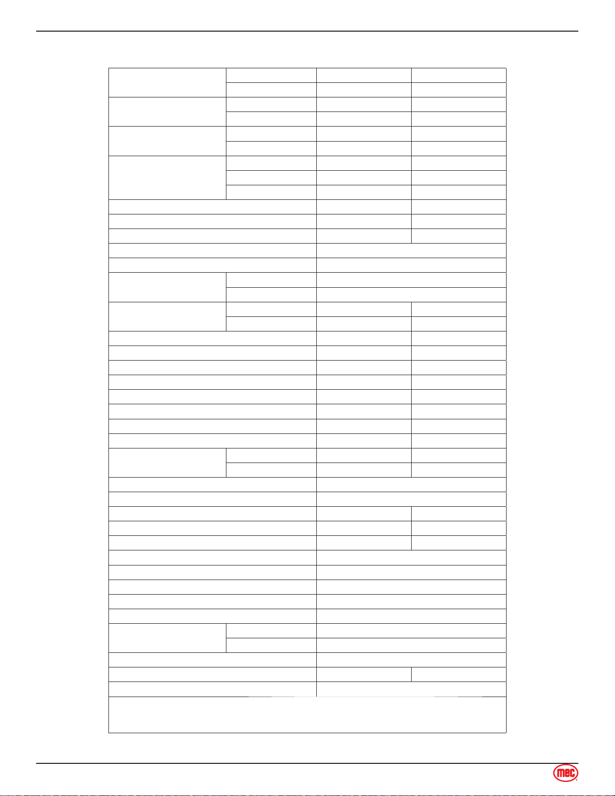
Machine Specifications
Working Height* Indoor 24.4 ft 7.43 m
Outdoor 19 ft 5.79 m
Platform Height Indoor 18.4 ft 5.6 m
Outdoor 13 ft 4 m
Maximum Drive Height Indoor 18.4 ft 5.6 m
Outdoor 13 4 m
Stowed Height Top Guardrail 83.3 in 2.12 m
Guardrails Folded 79 in 2.0 m
Platform Floor 39 in 1.0 m
Platform Extension Length 23.6 in 0.6 m
Machine Weight** (Unloaded) 2,820 lbs 1,280 kg
Maximum Lift Capacity 500 lbs 227 kg
Deck Extension Capacity 1 Person / 250 lbs (113 kg)
Xtra Deck Capacity 1 Person / 250 lbs (113 kg)
Maximum Occupants Indoor 1
Outdoor 1
Manual Force Indoor 45 lbs 200 N
Outdoor 45 lbs 200 N
Platform Length (Extended) 78 in 2.0 m
Platform Length (Retracted) 54 in 1.4 m
Width (Overall) 32 in 0.81 m
Platform Dimensions (Length × Width) 53.9 × 27.6 in 1.37 × 0.7 m
Wheel Base 44.5 in 1.13 m
Turning Radius - Inside 17.7 in 0.45 m
Ground Clearance - Stowed 2.4 in 6.0 cm
Ground Clearance - Elevated 0.6 in 1.5 cm
Drive Speed (Proportional) Stowed 0-2.5 mph 0-4.0 km/h
Raised Or Extended 0-0.5 mph 0-8.0 km/h
Gradability 25%/14°
Maximum Side Slope - Stowed 5°
Ground Pressure/Wheel 116 psi 8.2 kg/cm2
Maximum Wheel Load 990 lbs 450 kg
Occupied Floor Pressure 242 psf 1,177 kg/m2
Maximum Operating Wind Speed 28 mph / 12.5 m/sec (45 km/h)
Tire Size 9 × 4 inch / 230 × 100 mm
Lug Nut Torque 19 Ft-lbs / 25.5 N-m, Secured with cotter pin
Hydraulic Pressure 2,320 psi/ 160 bar
Power System Voltage 24 Volt DC
Battery Charger Input 110-230 V AC, 50-60 Hz
Output 24 Volt DC
Batteries Two 12 Volt Deep Cycle 115Ah
Chassis Inclination 1.5 Side 3.0 Inline
Airborne Noise Emissions <70 dB
Meets applicable requirements of ANSI A92.20-2018.
*Working Height adds 6 feet (2 m) to platform height.
**Weight may increase with certain options.
Machine Specifications
Section 3 - Specifications