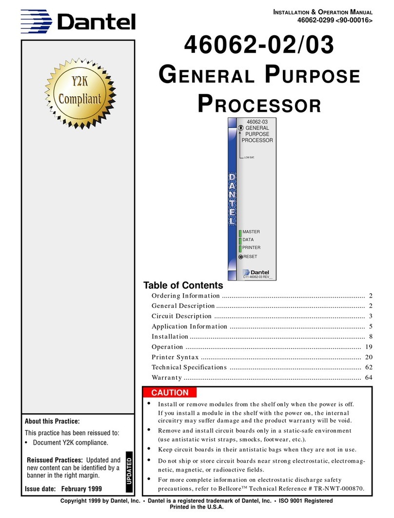
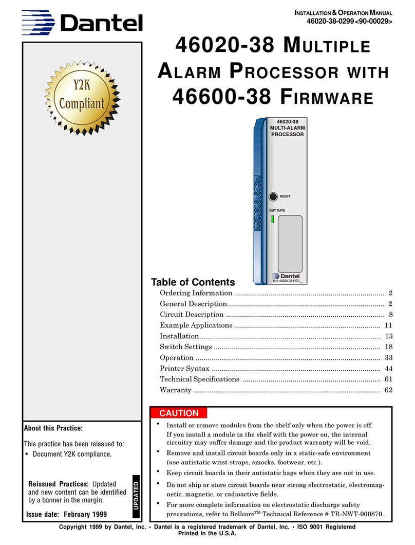
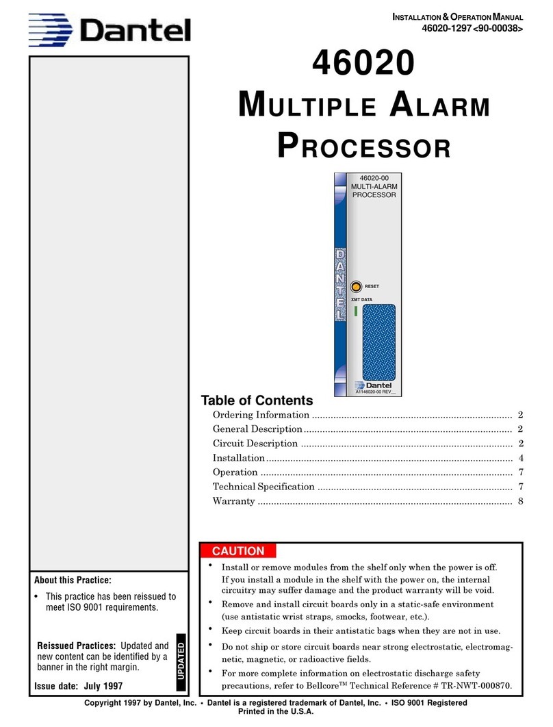
Dantel 46020-41 User manual

CAUTION
Install or remove modules from the shelf only when the power is off.
If you install a module in the shelf with the power on, the internal
circuitry may suffer damage and the product warranty will be void.
Remove and install circuit boards only in a static-safe environment
(use antistatic wrist straps, smocks, footwear, etc.).
Keep circuit boards in their antistatic bags when they are not in use.
Do not ship or store circuit boards near strong electrostatic, electromag-
netic, magnetic, or radioactive fields.
For more complete information on electrostatic discharge safety
precautions, refer to BellcoreTM Technical Reference #TR-NWT-000870.
Copyright 1999 by Dantel, Inc. • Dantel is a registered trademark of Dantel, Inc. • ISO 9001 Registered
Printed in the U.S.A.
INSTALLATION&OPERATION MANUAL
46020-41-1299<90-00065>
46020-41 MULTIPLE ALARM
PROCESSOR WITH 46641-00
FIRMWARE
About this Practice:
This practice has been reissued to:
• Update
Ordering Information
section.
Issue date: December 1999
Reissued Practices: Updated
and new content can be identified
by a banner in the right margin.
UPDATED
Table of Contents
Ordering Information ............................................................................ 2
General Description ............................................................................... 2
Circuit Description .............................................................................. 12
Example Applications .......................................................................... 13
Installation .......................................................................................... 17
Switch Settings .................................................................................... 21
Operation ............................................................................................. 27
Printer Syntax ..................................................................................... 36
Technical Specifications ....................................................................... 51
Warranty ............................................................................................. 52
46020-41
MULTI-ALARM
PROCESSOR
C11-46020-41 REV__
XMT DATA
RESET

PAGE 2 46020-41-1299<90-00065>
ORDERING INFORMATION
NOTE: This section lists the different options available for this product. To order any of the available
options, contact Dantel Inside Sales through our toll-free number, 1-800-432-6835.
OPTION NUMBER FEATURES
D11-46020-41 Multiple Alarm Processor equipped with B17-46641-00 Firmware.
GENERAL DESCRIPTION
T
he 46020-41 Multiple Alarm Processor (MAP) is part of a
Dantel 460 Alarm and Control System. It is a 46020 MAP
with 46641-00 firmware. This chapter describes the features of
the MAP and firmware, and how they work as part of a complete
system.
MAP PORTS
The firmware allows a MAP to operate in several different applica-
tions of a 460 Alarm and Control System. The MAP provides three
different data interface points, and all of them are affected by the
firmware. Here is a brief description of each of the ports:
Master Port
♦Reports alarm data to an alarm center and responds to control
point commands.
The alarm center may be a personal computer or an alarm
system master. For example, it could be an E-System master
the MAP communicates with through a 46033 E-System
Adapter.
♦May also connect to another device as an intermediary point in
reporting data to an alarm center.
This device could be a 46062 General Purpose Processor or
another MAP (using DCP, TBOS or DCPF protocol).
♦Uses TABS protocol to communicate with network elements
and AT&T remotes that use TABS protocol for alarm reporting.
Printer Port
♦Connects to a standard ASCII (VT-100) terminal, with or with-
out a printer,
or
CONTINUED . . .
NOTE:
In order to work, the MAP must
be configured. Configuration de-
fines how the MAP will function,
such as what alarms it will poll
and what control points it will op-
erate. The Printer Syntax in this
manual cannot be used for config-
uring the system.
To configure, use T/Shell software
with the MAP 41 Editor Module
and an IBM-compatible computer.
Refer to the software manual for
complete instructions.
UPDATED

46020-41-1299<90-00065> PAGE 3
♦Connects to Dantels 46001 Status Monitor.
You can use the terminal or status monitor for local alarm
reporting. The terminal also can operate controls.
♦May also operate as a master port (when youre using TABS,
TBOS, DCP, or DCPF protocol on it).
♦Works with T/Shell software to configure MAP memory.
Data Port
♦Can process up to 128 displays (8,192 points) of alarms and
controls. There can be any combination of alarm and control
displays; for example, 96 displays of alarms and 32 displays
of controls.
These may be discrete alarm points connected to 46009 or
46010 Multiple Alarm Transmitters (MATs) and control points
wired to 46028 or 46029 Control Point Modules (CPMs).
♦The MATs and CPMs also may be connected to SLC 96 and
Series 5 equipment.
Refer to Fig. 1. You can wire the Smart Block, using DCM
protocol, to multiple bays of SLC 96 devices. (Only one bay is
shown in Fig. 1.)
The Multiple Alarm Combiner (46023-14 Smart MAC) and the
46020 Multiple Alarm Processor (MAP) work specifically with
SLC 96 and Series 5 devices.
♦Can also communicate with alarm and control points through
TBOS serial equipment.
♦Uses TABS protocol to communicate with network elements
and AT&T remotes that use TABS for alarm reporting.
♦Can connect to another MAP (using TBOS, DCP, or DCPF
protocol) that communicates with the alarm and control points.
♦Is called the MAP port when it is connected to a 46023-14
Smart MAC and communicates with DCP or DCPF devices.
GENERAL DESCRIPTION
NOTE:
With SLC 96 and Series 5 equip-
ment, use the following CPMs
only: 46028-02, 46028-03, and
46029-02. Only these CPMs allow
downloading the time period for
the alarm cutoff (ACO).
NOTE:
The 46020-41 MAPs Data Port is
usually factory-wired to one or
more 46023-14 Smart Multiple
Alarm Combiners (SMACs). The
SMAC serves to expand the MAPs
single TTL Data Port out to mul-
tiple RS-422 Data Ports. In this
situation, the MAPs port which
communicates with the SMAC is
referred to as the MAP Port
the Data Port having been relo-
cated to the outputs of the SMAC.

PAGE 4 46020-41-1299<90-00065>
FIG. 1 - SLC 96, SMART BLOCK, AND ALARM & CONTROL SHELF DIAGRAM
A
B
TYPICALSYSTEMS
These diagrams show examples of how you can use the 46020 MAP
in typical systems. Fig. 2 shows a basic system and Fig. 3 shows
a system with an intermediate MAP.
GENERAL DESCRIPTION

46020-41-1299<90-00065> PAGE 5
FIG.2 - MAP PORTS AND PROTOCOLS
From Alarm
and
Control Points
To Alarm
Reporting
Equipment
Data Port
DCM
TBOS
TABS
DCP
DCPF To Local
Monitoring
Equipment
Master Port
TBOS
DCP
DCPF
TABS
Printer Port
TBOS
DCP
DCPF
Printer (ASCII)
TABS
MAP
46020-41
Comm.
Sub-Assy
FIG. 3 - EXAMPLE SYSTEM WITH INTERMEDIATE MAP
Serial Port 1
DATA/MAP PORT
MAP
46020-41
Master Port
MAC
46022-12
or
SMAC
46023-14
MAP
46020-41
(Intermediate)
TBOS/TABS
Comm.
Sub-
Assy
(Opt.)
49008,
49009,
49029,
49013
Printer Port
SITE A
SITE B
RS-422
SERIAL
DATA
PORTS
2 - 8
2
3
4
5
6
7
8
RS-422
SERIAL
DATA
PORTS
2
3
4
5
6
7
8
1
RS-422
Comm.
Sub-
Assy
49008
Master Port
Printer Port
TTL
DATA/MAP PORT
TTL
RS-232, RS-422/485, OR 202 TONE
RS-232
MAC
46022-12
or
SMAC
46023-14
GENERAL DESCRIPTION

PAGE 6 46020-41-1299<90-00065>
FIG.4-DATA PORT CONFIGURATION
DCM
TBOS
DCP*
DCPF*
TABS
Smart
MAC
46023-14
DCM
TBOS
TABS
46020
MAP
with
46641-00
Firmware
Data/MAP Port
MAC
46022-12
or
SMAC
46023-14
46020-41
MAP
Data/MAP Port
DCP/F
DEVICE
*
DCP(F) not available with 46023-14 SMAC
DATA CAPACITY
Master and Printer Ports
The MAP can handle 8,192 alarm and control points (128 displays)
except when you use TBOS protocol.
When TBOS is used on the master and printer ports, the amount
of alarm data the MAP can address is limited. TBOS is limited to
eight displays of alarms and controls on the master port and an
additional eight displays of alarms and controls on the printer port
(a total of 16 displays).
GENERAL DESCRIPTION

46020-41-1299<90-00065> PAGE 7
Data Port
With TABS, DCP, or DCPF protocols on the master and/or
printer ports, the data port can communicate with up to 8,192
alarm and control points. See Fig. 2 for an illustration of these
protocols.
If TBOS is used on the master port, the data port is limited to 512
alarm and 512 control points (eight displays).
If TBOS is used on both master and printer ports, the data port
can communicate with up to 1,024 alarm and 1,024 control points.
See Fig. 5 for an illustration of TBOS on master and printer ports.
FIG. 5 - TBOS ON THE MASTER AND PRINTER PORTS
TBOS
Up To 8 TBOS
Displays
(Displays 1-8)
Reported to
Operations Center
TBOS
DATA
Printer Port
Master Port
MAC
46023-14
8
SERIAL
PORTS
(DCM, TBOS,
PROTOCOLS)
2
3
4
5
6
7
8
1
MAXIMUM OF 1024 ALARMS
& 1024 CONTROLS
Discrete or
Serial Port
Serial Port
Serial Port
Serial Port
Serial Port
Serial Port
Serial Port
Serial Port
Up To 8 TBOS
Displays
(Displays (9-16)
Reported to
Operations Center
MAP
46020-41
Comm.
Sub-
Assy
(Opt.)
49008,
49029,
49013
PROTOCOLS
There are four communications protocols available for the master
port, four for the printer port (plus a printer syntax using ASCII
format), and five for the data port. Refer to Fig. 2.
MASTER AND PRINTER PORTS
TABS
This protocol is used to communicate with network elements and
AT&T remotes that use this protocol for alarm reporting.
DCP
This protocol is used when the MAP interfaces another MAP, a
personal computer, or an external alarm master (such as an
E-System master interfaced through an E-System Adapter).
CONTINUED . . .
GENERAL DESCRIPTION

PAGE 8 46020-41-1299<90-00065>
DCPF
This is a modified DCP protocol with improved error detection. It
is used when the MAP interfaces another MAP, a General Purpose
Processor, or a Status Monitor.
TBOS
This protocol is used when the MAP interfaces a TBOS serial port,
such as on an E2A remote or on the data port of another MAP
(refer to Fig. 3).
Printer
This syntax establishes the coding for the printer port to interface
a standard ASCII (VT-100) terminal. The Printer Syntax chapter
contains the user commands for operating the terminal.
DATA PORT
TABS
This protocol is used to communicate with network elements and
AT&T remotes that use this protocol for alarm reporting.
TBOS
This allows the MAP to communicate with TBOS serial equip-
ment. This can be another MAP as shown in Fig. 3.
DCM
This protocol communicates with discrete points only. The MAP
interrogates MATs (Multiple Alarm Transmitters) for alarm data
and operates control points on CPMs (Control Point Modules).
The MATs and CPMs also can interface SLC 96 and Series 5
equipment as shown in Fig. 1.
DCP
This protocol communicates with another MAP using DCP proto-
col (similar to the TBOS example shown in Fig. 3).
DCPF
This protocol communicates with another MAP using DCPF
protocol (similar to the example shown in Fig. 3).
NOTE:
DCP and DCPF are unavailable
for use by the Data Port when us-
ing a 46023-14 Smart MAC.
GENERAL DESCRIPTION

46020-41-1299<90-00065> PAGE 9
INTERFACES
Master Port
The master port requires a subassembly to be mounted on the
MAP in order to provide the proper interface to other equipment.
When TBOS or TABS is used on the master port, the most com-
mon is a 49008 subassembly providing an RS-422 interface. Other
subassemblies are available for special applications.
When DCP or DCPF is used on the master port, the subassembly
is usually a 49009 or 49029 with an RS-232 interface.
Printer Port
The printer port has a built-in RS-232 interface. If you require a
different interface on the printer port, you can add a Dantel 46035
Converter Module with the appropriate subassembly between the
MAP and the other equipment.
Data Port
The data port of the MAP communicates through transistor-
transistor logic (TTL). This means communications cannot extend
beyond the shelf where the MAP is installed. To communicate
beyond the shelf, you must connect the data port to a 46035
Converter Module, 46022 Multiple Alarm Combiner (MAC), or
46023 Smart MAC for conversion to the appropriate data commu-
nications interface.
A 46022-12 MAC or a 46023-14 Smart MAC has eight communica-
tions channels or ports. A 46022-20 MAC has one channel. This
channel, however, can be any communications subassembly such
as a 49013 202 Tone Modem. The data port supports multiple
MACs.
In communicating with alarm and control points, the data port
can use DCM, DCP, DCPF, TABS, or TBOS protocols on any of
the MAC channels. However, only one protocol can be used on any
one channel. The protocol(s) used on the data port do not have to
be the same as those used on the printer and master ports. For
example, DCP could be used on the master port, PRINTER syntax
on the printer port, and DCM and TBOS on the data port.
Transmission Distances
Fig. 6 shows the maximum cable lengths for data transmission
interfaces.
NOTE:
The 46023-14 Smart MAC cannot
be used in parallel with a
46022-12 or 46020-20 MAC
NOTE:
To communicate with SLC 96 or
Series 5 equipment, the MAC(s)
must be a 46023-14 SMAC.
GENERAL DESCRIPTION

PAGE 10 46020-41-1299<90-00065>
FIG.6-MAXIMUM CABLE LENGTHS FOR DATA TRANSMISSION INTERFACES
40
RS232
RS422 BALANCED
RS423 UNBALANCED
100 1 10K 100K 1M 10M
10K
4K
1K
100
50
10
CABLE LENGTH (FEET)
DATA MODULATION RATE (BAUDS)
BATTERY BACKUP
The MAP has a battery backup to preserve the system configura-
tion information that has been placed in memory. You can set
switches on the MAP to retain the information in memory, even if
the power to the MAP is interrupted. If you do not set the
switches to retain the memorys contents, configuration informa-
tion is erased when the power is restored. To learn how to set
these switches, refer to the Switch Settings chapter.
RESET
On the front panel of the MAP, there is a recessed reset button.
When you push this button, it executes a complete, or hard, reset.
The effect is the same as removing power from the MAP. When
power is restored later, the information in the MAPs memory is
saved ... only if you have set the switches to retain it (see Battery
Backup paragraph). If you have not set the switches to save the
memory, it will be erased.
The MAP also has a protective (watchdog) circuit. If the soft-
ware encounters a problem and is unable to refresh the protective
circuit, a complete reset automatically occurs after 1.2 seconds.
GENERAL DESCRIPTION

46020-41-1299<90-00065> PAGE 11
DERIVEDDISPLAY
The 46641-00 firmware supports a derived display, in which you
can set alarm points based on the condition of actual alarms. The
derived display determines when to set an alarm based on a series
of and/or conditions. For example, you can set an alarm in the
derived display if Alarm Point 1 and Alarm Point 2 or Alarm
Point 3 in Display 1 are showing failures.
EXTENDED DEVICE FAILURE
The extended device failure feature allows the firmware to set an
alarm bit to some location other than the standard ones. If you
have a special need, you can reassign the communications failure
bit to another alarm bit on the same display or even on a different
display.
DIP SWITCHES
There are seven banks of DIP switches on the MAP. Each bank
has eight levers, and the banks are numbered S1 through S7.
S1 through S6 are used to set the default settings, and S7 is not
used.
Refer to Fig. 7 for a DIP switch location diagram. The switches are
not numbered on the board.
FIG. 7 - 46020 MAP VIEWED FROM THE TOP
GENERAL DESCRIPTION
VIEW
ROTATED
90 DEGREES
1 2 3 4 5 6 7 8 1 2 3 4 5 6 7 8 1 2 3 4 5 6 7 8 1 2 3 4 5 6 7 8
SWITCH 1 SWITCH 2 SWITCH 3 SWITCH 4
UP = OFF
DOWN = ON
1 2 3 4 5 6 7 8
1 2 3 4 5 6 7 8
1 2 3 4 5 6 7 8
S5
S6
S7
1 2 3 4 5 6 7 8
SWITCH 5

PAGE 12 46020-41-1299<90-00065>
CIRCUIT DESCRIPTION
F
ig. 8 shows the functional schematic of a 46020 MAP
equipped with 46641-00 Firmware. The circuit consists of the
following:
♦A microprocessor with EPROM (Erasable Programmable Read-
Only Memory).
♦Three ports:
Master port
Printer port
Data port
♦Three parallel input/output interfaces (must be connected to
other modules in the same shelf as the MAP):
Interface for Dantels 46022-XX or 46023-14 Multiple Alarm
Combiners (MACs).
Interface for Dantels 46019 Summary Alarm Module (SAM).
An unassigned auxiliary input/output.
♦Regulated power supply.
Binary data goes to and from the microprocessor by way of the
systems input/output. It is applied to each port through a series
of protectively buffered ACIAs (Asynchronous Communications
Interface Adapters).
Master port
Communicates with an external personal computer or other alarm
reporting equipment through a plug-in subassembly.
Printer port
Communicates with an external standard ASCII (VT-100) termi-
nal, personal computer, or other alarm reporting equipment
through an on-board RS-232 interface.
Data port
Communicates either directly or through other Dantel interface
modules with remote alarm and control devices using seven TTL
buses designated TXD, RXD, RTS, CTS, DCD, DSR, and DTR.
By setting switches, you can determine the default configurations
of the ports. These configurations affect the way the MAP func-
tions when you begin operation.
The on-board regulated power supply uses -21 to -56 VDC input
power to provide +5 and ± 12 VDC regulated power for the
modules circuits. The power supply also provides operating power
for the master port communications subassembly.
NOTE:
In order to work, the MAP must
be configured. Configuration de-
fines how the MAP will function,
such as what alarms it will poll
and what control points it will op-
erate. The Printer Syntax in this
manual cannot be used for config-
uring the system.
To configure, use T/Shell software
with the MAP 41 Editor Module
and an IBM-compatible computer.
Refer to the software manual for
complete instructions.

46020-41-1299<90-00065> PAGE 13
CIRCUIT DESCRIPTION
32
31
30
29
39
41
40
42
23
24
26
27
46
45
43
44
54
51
53
55
50
49
56
52
8
MEMORY
MEMORY
MEMORY
MEMORY
DECODER
PORT 3
(MASTER)
ADR
CPU
ADR
PARALLEL INPUT/OUTPUT
35
17
POWER
REGULATOR
1
2
3
4
5
6
7
RXD
CTS
DCD
DSR
TXD
DTR
RTS
47 +5 VDC OUTPUT
-21 TO -56 VDC
PORT 2
(PRINTER)
PORT 1
(DATA)
OPTIONAL
COMMUNICATION
SUB-ASSEMBLY
GROUND
13
9
11
14
10
12
TX DATA (BB)
RX DATA (BA)
DSR
DTR
RTS
DCD
TX+
TX-
RX+
RX-
RS 422/
RS 485
49008
S/A
RTS
RD
DTR*
DCD
GND or CTS*
TD
RS 232
49009 or
49029 S/A
Balanced Output
DIST. XMT
Balanced Input
DIST. RCV
202
Modem
49013
S/A
LEV A ALM
LEV B ALM
LEV C ALM
LEV D ALM
WRT CL 0
WRT CL 1
WRT CL 2
WRT CL 3
CLK 0
CLK 1
CLK 2
CLK 3
CHAN. ADD 0
CHAN. ADD 1
CHAN. ADD 2
CHAN. ADD 3
CARD. ADD 0
CARD. ADD 1
CARD. ADD 2
DATA
WRT
ALM
DIS. REQ
DATA ENB.
EXT. INTERRUPT
MULTIPLE ALARM PROCESSOR,
46020-41
S1
THRU
S7
DATA
* Available for
49029 Only
22
20
21
19
16
15
EXAMPLE APPLICATIONS
F
ig. 9 shows a TBOS and discrete alarms interfaced to an
E-system using several 46020-41 MAPs. Fig. 10 shows a
system using a 46020-41 MAP to report discrete points.
TBOS (SERIAL PORTS) AND DISCRETE POINTS INTERFACED TO ATL1 GPP
Refer to Fig. 9. A TL1 GPP is shown interfacing multiple MAPs
using DCPF protocol between the master port of the MAPs and the
data port of the TL1 GPP. The data port of each MAP is then
interfaced to remote sites through MACs, 46035 Converter Mod-
ules, or 44118 VF Bridges. MAPs 1/2 and 5/6 are shown communi-
cating with remote MAPs through one port of the
MAC-14s.
At the remote sites, each MAP is communicating through
Port 1 of the MAC-12s, using DCM protocol, to discrete alarm and
control points. Ports 2-8 connect to TBOS serial alarm and control
CONTINUED . . .
FIG.8-FUNCTIONAL SCHEMATIC

PAGE 14 46020-41-1299<90-00065>
equipment. MAP 7/8 is communicating, through a MAC-20 and
using DCM protocol, with remotely located discrete alarm and
control points.
The TL1 GPP reports TL1 messages directly to an Alarm Center
(NMA).
DISCRETE POINTS INTERFACED TO ALARM AND CONTROL SYSTEM
Refer to Fig. 10. This example application uses one MAP to
process data between an alarm system master or personal com-
puter, a printer or standard ASCII (VT-100) terminal, and remote
discrete alarm and control points. The 46022-20 MAC is equipped
with a data communications subassembly to interface the remote
MATs and CPMs.
OTHER MODULES
Refer to Fig. 10. The 46019 Summary Alarm Module (SAM)
controls audible and/or visual alarm devices. This module pro-
vides:
♦TTL (Transistor-Transistor Logic) and/or optically coupled
inputs,
♦Latching or following mode,
♦Selectable time-out for quadruple alarm levels.
You can use the 46018 Audible Alarm Module with the 46019 to
provide the audible signal. For more information, refer to the
manuals for these devices.
EXAMPLE APPLICATIONS

46020-41-1299<90-00065> PAGE 15
FIG. 9 - TBOS AND DISCRETE ALARMS INTERFACE TO ATL1 GPP
EXAMPLE APPLICATIONS
NMA
REMOTE SITES
AS NEEDED
DISCRETE
ALARM
DEVICES
MAT
MAT
MAT
MAT
CPM
R
S
4
2
2
REMOTE SITE
DISCRETE
ALARM
DEVICES
MAT
MAT
MAT
MAT
CPM
R
S
4
2
2
REMOTE SITE
DISCRETE
ALARM
DEVICES
MAT
MAT
MAT
MAT
CPM
REMOTE
SITE #1
2
0
2
R
S
4
2
2
46023-14
MAC
46062-22
TL1GPP
46023-14
MAC
R
S
2
3
2
46020
MAP
ADDR
3/4
46022-20
MAC 46020
MAP
ADDR
7/8
R
S
2
3
2
2
0
2
R
S
2
3
2
46020
MAP
ADDR
5/6
46035 46023-14
MAC
2
0
2
RS422
FIBER OPTIC OVERHEAD
2400 BAUD TBOS
512 ALARM POINTS
MAXIMUM PER TBOS PORT
R
S
2
3
2
46020
MAP
ADDR
1/2
DATA
PORT
RS422
TBOS
SERIAL
PORT
2-8
46022-12
MAC
DATA
PORT
1
DATA
PORT
2 - 8
46020
MAP
RS422
TBOS
SERIAL
PORT
2-8
46022-12
MAC
DATA
PORT
1
DATA
PORT
2 - 8
46020
MAP
2
0
2
512 ALARM POINTS
MAXIMUM PER
TBOS PORT
VOICE FREQUENCY
1200 BAUD TBOS
2048 ALARM
POINTS MAXIMUM
VOICE FREQUENCY
1200 BAUD
44118
BRIDGE
PORT 1
SUMMING
PORT
PORT 4
DCPF
PROTOCOL
DATA
PORT
SITE
# 2
SITE
# 3
DATA
PORT
PORT 2
PORT 3

PAGE 16 46020-41-1299<90-00065>
FIG. 10 - SYSTEM REPORTING DISCRETE POINTS
EXAMPLE APPLICATIONS
BYPASS
CARD
46009
MAT
3
BYPASS
CARD
46009
MAT
4
202
MODEM
49013
202
MODEM
49013
202
MODEM
49013
202
MODEM
49013
202
MODEM
49013
44118
ACTIVE
BRIDGE
SUM/DIST.
PORT
SUM/DIST.
PORT
SUM/DIST.
PORT
COMMON
PORT
TTL DATA BUS
ALARM
LEVEL A - D
TO
EXTERNAL
ALARM
SYSTEM
OR
COMPUTER
TO
PRINTER
OR
DUMB
TERMINAL
CPM 1
46028
MAT
46009
BYPASS
CARD
46009
MAT
2
OPTIONAL
46019
SAM
MASTER
PORT
PRINTER
PORT
CPM 2
46028
46022-20
MAC
46020-41
MAP
OPT
COMM.
SUB
ASSY

46020-41-1299<90-00065> PAGE 17
INSTALLATION
I
nstallation consists of installing the firmware subassembly,
installing the communications subassembly, setting switches,
installing the module in the shelf, clearing memory, configuring
the system, and testing the system.
1. Install the firmware subassembly, if necessary.
To install the subassembly:
♦Remove the four screws from the subassembly standoffs on the
MAP. Refer to Fig. 11 for the location of the firmware subas-
sembly.
♦Separate the subassembly top board from the main board. Be
careful not to bend any connector pins.
♦Insert the main subassembly board into the connectors on the
MAP.
♦Install two screws at the end of the main subassembly board
next to the front panel of the MAP.
♦At the other end of the main subassembly board, install the two
standoffs supplied with the firmware.
♦Insert top subassembly board, (S5, S6, S7) into the connectors
on the main subassembly board.
♦Install three screws to fasten the top subassembly.
2. Install communications subassembly, if necessary.
Refer to Fig. 11 for the location of the master port communications
subassembly mounting. Follow these steps:
♦If a subassembly is not already installed, remove the three
screws from the mounting standoffs.
♦Remove the hole plug from the front panel of the module.
♦To place the subassembly, insert the subassembly pins into the
module sockets.
♦Examine the connector pins to be sure each one goes straight
into the socket.
♦Install the screws in the mounting standoffs.
For information on how to set the strap options and how to operate
the subassembly, refer to the manual for that subassembly.

PAGE 18 46020-41-1299<90-00065>
FIG. 11 - MAP SUBASSEMBLY LOCATIONS
DATA
XMT
LED
COMMUNICATIONS
SUBASSEMBLY
MOUNTING
RESET SWITCH
8 7 6 5 4 3 2 187654321
S4 S3 S2
876543218 7 6 5 4 3 2 1
S1
87654321
S7
87654321
S5
8 7 6 5 4 3 2 1
S6
FIRMWARE
SUBASSEMBLY
INSTALLATION

46020-41-1299<90-00065> PAGE 19
FIG. 12- 46020 MAP VIEWED FROM THE TOP
3. Set switches.
Set switches S1 through S7 on the MAP. Refer to Fig. 12 and the
chapter on Switch Settings.
4. Install the module in the shelf.
Slide the MAP module along the card guides of the correct slot.
Firmly seat the module in the 56-pin edge connector.
The shelf is usually wired at the factory, and you do not have to
wire the 56-pin edge connector. If it is necessary for you to wire it,
refer to Fig. 13.
5. Clear memory, if necessary.
The following paragraph tells you how to clear the memory in the
MAP. Follow these instructions only if you are installing the
MAP in a system for the first time or if you need to clear all
memory.
The MAP has a battery-backed memory that can retain system
configuration in the event of a power interruption to the MAP. To
clear the memory, follow these steps:
♦Set switch S5-2 in the DOWN position (refer to Fig. 12).
♦Plug the MAP into your system and apply power.
♦Wait ten seconds, then turn off power to the MAP.
♦Remove the MAP from the system and set switch S5-2 in the
UP position.
INSTALLATION
VIEW
ROTATED
90 DEGREES
1 2 3 4 5 6 7 8 1 2 3 4 5 6 7 8 1 2 3 4 5 6 7 8 1 2 3 4 5 6 7 8
SWITCH 1 SWITCH 2 SWITCH 3 SWITCH 4
UP = OFF
DOWN = ON
1 2 3 4 5 6 7 8
1 2 3 4 5 6 7 8
1 2 3 4 5 6 7 8
S5
S6
S7
1 2 3 4 5 6 7 8
SWITCH 5

PAGE 20 46020-41-1299<90-00065>
FIG. 13 - 46020 MAP EDGE CONNECTOT PIN DESIGNATIONS
MAP MASTER PORT
CONNECTIONS
MASTER
PORT
MASTER PORT
MASTER PORT
56 55
54 53
52 51
50 49
48 47
46 45
44 43
42 41
40 39
38 37
36 35
34 33
32 31
30 29
28 27
26 25
24 23
22 21
20 19
18 17
16 15
14 13
12 11
10 9
87
65
43
21
CIRCUIT SIDE OF PC BOARD
COMPONENT SIDE OF PC BOARD
AUXILIARY INPUT/OUTPUT
DATA
CARD ADDRESS 2
CARD ADDRESS 1
ALM
+5 VDC OUTPUT (FOR EXTERNAL USE)
CHANNEL ADDRESS 1
CHANNEL ADDRESS 2
CLK ENB
-21TO -56VDC
LEVEL D
R2
R ∅
GROUND
TD
DSR
DISPLAY REQUEST
CARD ADDRESS ∅
DATA ENABLE
WRT
CHANNEL ADDRESS ∅
CHANNEL ADDRESS 3
W3
W2
DTR
DCD
RD
RTS
RTS
EXTERNAL INTERRUPT
PRINTER PORT PRINTER PORT
MULTIPLE
ALARM
COMBINER
AUXILIARY INPUT/OUTPUT
MULTIPLE
ALARM
COMBINER
LEVEL A
LEVEL C
SUMMARY
ALARM
MODULE
R3
R1
DTR
DSR
CTS
TTL DATA PORT
TXD
DCD
RXD
TTL DATA PORT
AUXILIARY INPUT/OUTPUT
LEVEL B SUMMARY
ALARM
MODULE
W1
W∅
MULTIPLE
ALARM
COMBINER
MULTIPLE
ALARM
COMBINER
AUXILIARY INPUT/OUTPUT
MASTER
PORT
COMPONENT
SIDE CIRCUIT
SIDE
22 21
20 19
16 15
49008 49009 49012 or 49013
49029
RD- N/C BALANCED
INPUT
DTR
N/C RTS DISTRIBUTION
TRANSMIT
RTS
RD+ RD BALANCED
INPUT
RD
SEE
TABLE BELOW
FOR
OPTION SPECIFIC
PIN DESIGNATIONS
SEE
TABLE BELOW
FOR
OPTION SPECIFIC
PIN DESIGNATIONS
49008 49009 49012 or 49013
49029
TD- TD BALANCED
OUTPUT
TD
N/C DCD DISTRIBUTION
RECEIVE
DCD
TD+ N/C GND or
CTS BALANCED
OUTPUT
INSTALLATION
This manual suits for next models
1
Table of contents
Other Dantel Computer Hardware manuals