Dantel 46512 User manual

CAUTION
•Install or remove modules from the shelf only when the power is off.
If you install a module in the shelf with the power on, the internal
circuitry may suffer damage and the product warranty will be void.
•Remove and install circuit boards only in a static-safe environment
(use antistatic wrist straps, smocks, footwear, etc.).
•Keep circuit boards in their antistatic bags when they are not in use.
•Do not ship or store circuit boards near strong electrostatic, electromag-
netic, magnetic, or radioactive fields.
•For more complete information on electrostatic discharge safety
precautions, refer to BellcoreTM Technical Reference # TR-NWT-000870.
Copyright 1999 by Dantel, Inc. • Dantel is a registered trademark of Dantel, Inc. • ISO 9001 Registered
Printed in the U.S.A.
INSTALLATION & OPERATION MANUAL
46512-0999 <90-00083>
46512
41 MAP EDITOR
Issue date: September 1999
Reissued Practices: Updated and
new content can be identified by a
banner in the right margin.
UPDATED
Table of Contents
Ordering Information ........................................................................... 2
Installation............................................................................................ 2
Standards.............................................................................................. 3
Getting Started ..................................................................................... 6
MAP System Definition........................................................................ 9
MAP Data Path................................................................................... 78
MAP Parameters ................................................................................ 79
Terminal Emulator ............................................................................. 81
Warranty ............................................................................................. 92
About this Practice:
This practice has been reissued to:
• Document up-issue of the product
to incorporate enhancements for
operating on PC’s with clock
speeds in excess of 200 MHz.

PAGE 2 46512-0999 <90-00083>
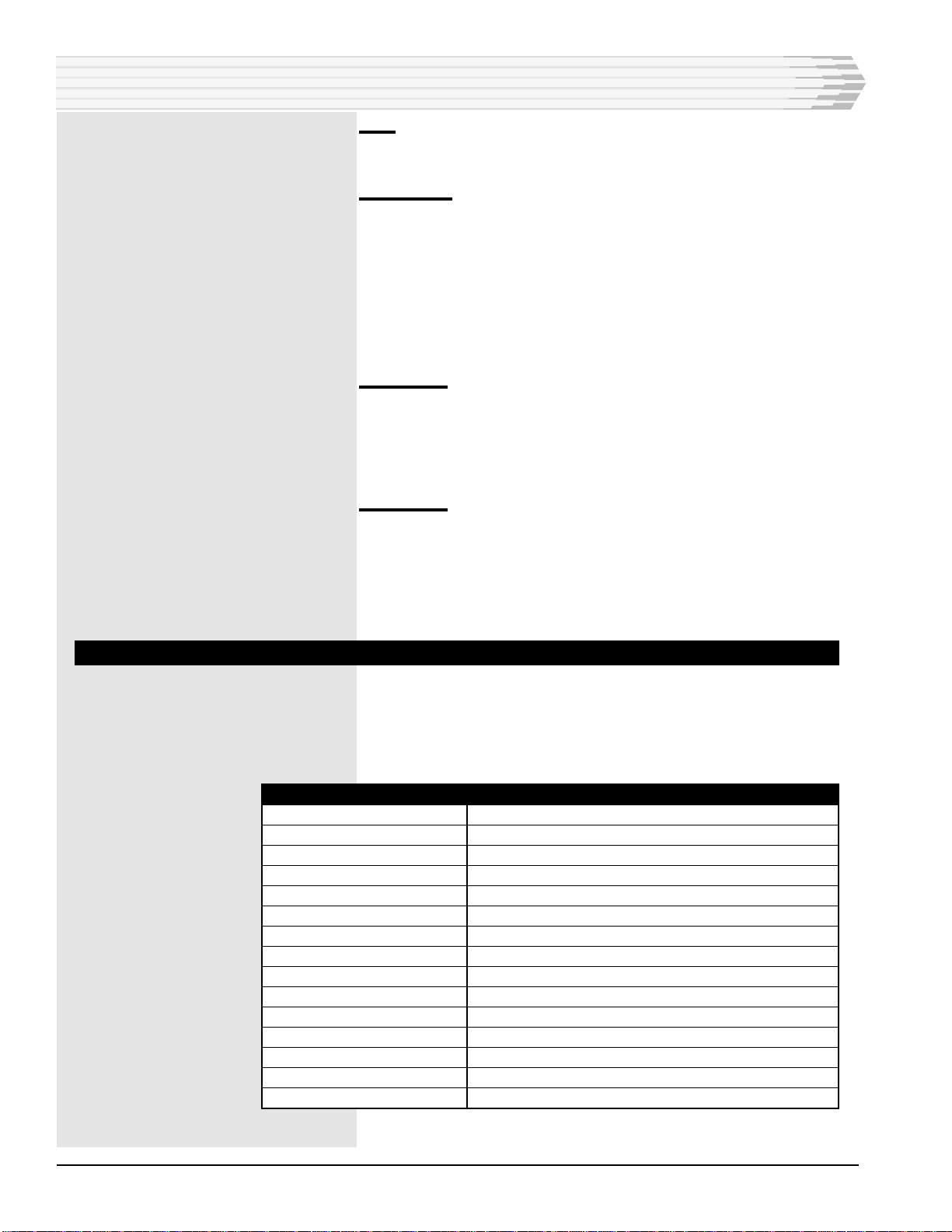
ORDERING INFORMATION
NOTE: This section lists the different options available for this product. To order any of the avail-
able options, contact Dantel Inside Sales through our toll-free number, 1-800-432-6835.
OPTION NUMBER FEATURES
C22-46512-02 41 MAP T/Shell; Version 1.4
INSTALLATION
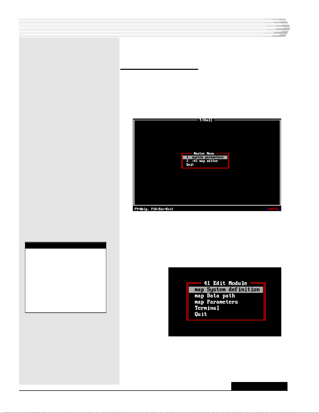
This chapter explains how to install the T/Shell software
program with the 46512 41 MAP Editor on your computer.
The T/Shell program can be installed on an IBMTM-compatible
computer equipped with the following:
♦640K of memory
♦CGA/EGA/VGA color (recommended), monochrome, or LCD
monitor
♦One serial port
♦One 3.5" diskette drive
♦One hard disk drive
♦DOS version 3.0 or later
To install the software program on your computer:
1. Turn on the power to your computer and monitor. Wait for the
DOS (Disk Operating System) prompt to appear.
2. Insert the 46512 software disk from Dantel into the diskette drive.
3. Make sure you are in the hard disk drive (normally C) where you
want to install the program. At the prompt type MD TSHELL to
make a directory called TSHELL.
4. Press Enter.
5. At the prompt type CD TSHELL.
6. Press Enter to change to the TSHELL directory.
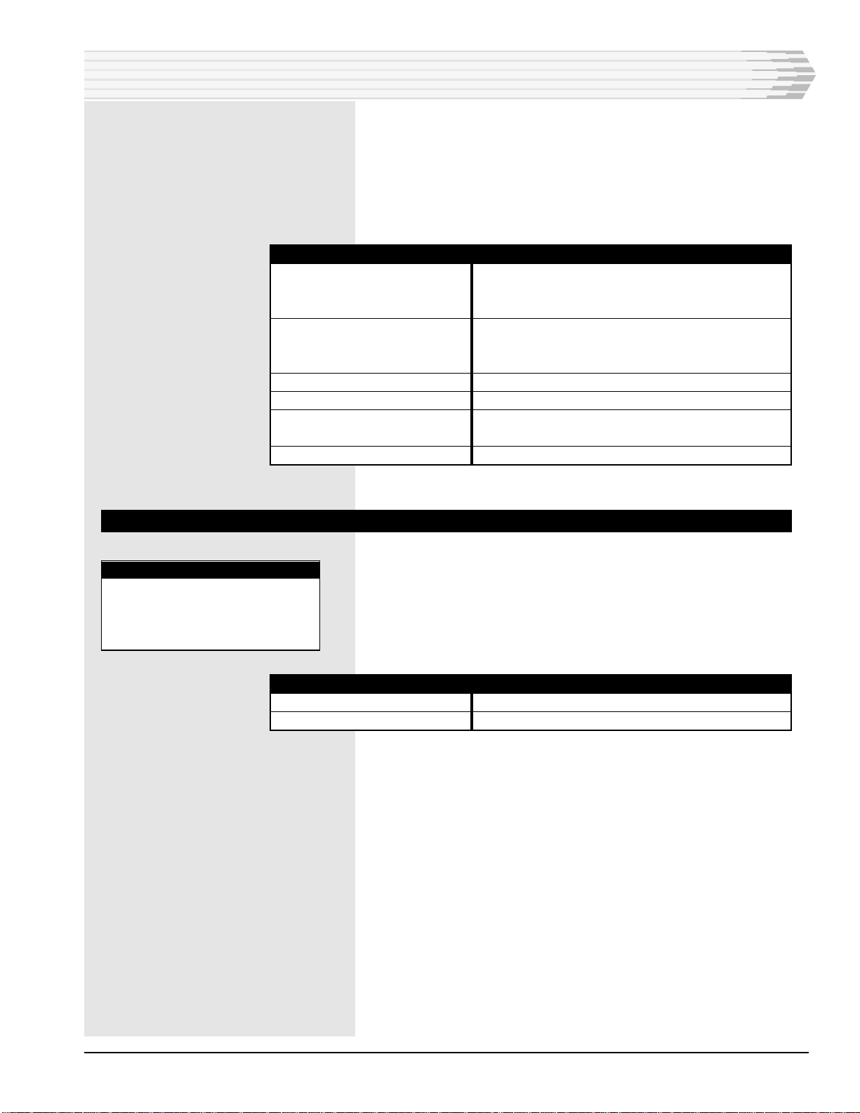
The following T/Shell programs are not copy-protected. Do not copy
them into a directory that has T/Shell programs not listed below or
has the same programs with lower version numbers.
♦Status Monitor GPP Editor B22-46502-XX, Version 2.0
♦ TL1 GPP Editor F22-46504-XX, Version 2.2
♦ 40 MAP Editor C22-46508-XX, Version 1.3
♦41 MAP Editor C22-46512-XX, Version 1.1
CONTINUED . . .
NOTE:
If a TSHELL directory al-
ready exists on your comput-
er, you may not be able to
copy the new T/Shell program
into the same directory. Dan-
tel no longer provides copy
protection with its software.
T/Shell programs that are not
copy-protected must not be
placed in the same directory
with T/Shell programs that
are copy-protected. If you do
not know the version number
of a T/Shell program that is
already installed on your
computer, go to the first
screen of the program. Press
the F1 (Info) key to display
the version number.
NOTE:
You can run T/Shell under
Windows 3.1 or Windows 95.
Refer to your Windows manu-
al for instructions.
UPDATEDUPDATED

46512-0999 <90-00083> PAGE 3
♦X.25 Sync Editor B22-46513-XX, Version 2.1
♦X.25 Cascade Editor A22-46516-XX, Version 1.0
♦TL1/NMA Converter Editor A22-46521-XX, Version 1.0
♦X.25 Cascade Editor A22-46522-XX, Version 1.0
♦Status Monitor GPP Loader A22-46703-XX, Version 1.0
7. Type COPY A:*.* This assumes that the disk is in drive A. If it is
in a different drive, type the letter of that drive.
8. Press Enter to copy all the files into your TSHELL directory from
the disk in your diskette drive.
9. After the software has been copied into the TSHELL directory,
store the disk in a safe place.
10. End of Installation section.
INSTALLATION
STANDARDS
This section describes those commands, key, and standards
common to all Dantel software packages.
SOFTWARE STANDARDS
HIGHLIGHT
A highlighted option in a menu is the currently selected option.
To activate an option, do either of the following:
1. Press Enter if the option is highlighted.
2. Type the letter of the hot key. A hot key is a specific key that can
open an option. With a color monitor, a hot key is indicated by a
yellow letter. With a monochrome monitor, a hot key is indicated by
a capital letter. In the Master Menu, the hot keys are the option
numbers. When you use the hot key method, the option does not
have to be highlighted.
F3
Opens the Terminal Emulation mode in most cases.
F8
Saves the entries that you make to the database configuration.
If there is more than one entry field on a line, the cursor must be
in the first field in order to save the information. See rule 1 of
F10 & Esc.

PAGE 4 46512-0999 <90-00083>
F9
Activates on-line help.
F10 & Esc
In most cases the F10 and Esc keys work interchangeably. The
following rules apply to these keys:
1. When editing a group of fields, returns the cursor to the first field.
When editing the first field, they exit that window.
2. When at a submenu, they return cursor to the previous menu.
3. When at the Master Menu, they exit the program.
Up Arrow
The up arrow usually does one of the following two things:
1. Selects the preceding option from a menu.
2. Selects the previous field within an option.
Dn Arrow
The down arrow usually does one of the following two things:
1. Selects the next option from a menu.
2. Selects the next field within an option.
FIELD EDITING STANDARDS
The software program checks each field for the correct type of
entry. If a valid entry for a certain field is alphabetic and a
numeric key is pressed, the computer beeps.
When editing fields, the following keys are active:
STANDARDS
KEY
Enter
Ctrl-Z
Ctrl-R
Back Arrow
Ctrl-H
Left Arrow
Right Arrow
Ctrl-Home
Ctrl-End
Del
Ins
Ctrl-Left Arrow
Ctrl-Right Arrow
Ctrl-K or Alt-K
Ctrl-D
FUNCTION
Accepts the field.
Erases the current field.
Restores the default value.
Deletes the previous character.
Lists the editing keys that are available.
Moves the cursor left within the field.
Moves the cursor right within the field.
Moves the cursor to the start of the field.
Moves the cursor to the end of the field.
Deletes the current character.
Toggles insert mode.
Moves the cursor left to the previous word.
Moves the cursor right to the previous word.
Deletes to the end of the field.
Calls up the Default Box if there is one.

46512-0999 <90-00083> PAGE 5
There may be times when the screen cannot display all the data.
In such cases, use special keys to scroll different parts of the
data onto the screen.
Usually these special keys are active only when the cursor is at
the first item (far left) in a given line of data. The special keys
and their functions are as follows:
DEFAULT BOX
When defining certain fields, a default box appears to aid in the
selection process. The default box displays the valid selections
for the current field that is being editing. Select from the default
box or type the entry. To select from the default box, use the
keys below, then press Enter.
KEY
Tab
Shift-Tab
FUNCTION
Moves the select bar down one selection.
Moves the select bar up one selection.
STANDARDS
NOTE:
The arrow keys are not active
in these default boxes. Choic-
es can be made only with the
TAB or SHIFT-TAB keys.
KEY
Up Arrow
Down Arrow
Home
End
PgUp
PgDn
FUNCTION
Moves the cursor up one line. When the
cursor is on the top line, the previous line
scrolls into the window.
Moves the cursor down one line. When the
cursor is on the bottom line, the next line
scrolls up into the window.
Brings the first page of data into the window.
Brings the last page of data into the window.
Brings the previous page of data into
the window.
Brings the next page of data into the window

PAGE 6 46512-0999 <90-00083>
GETTING STARTED
The T/Shell software program with the 46512-41 MAP Editor
lets you configure how 46020 Multiple Alarm Processor
(MAP) hardware modules will operate.
To start the T/Shell program:
1. Make sure that you are in the TSHELL directory.
2. Type TSHELL.
3. Press Enter. The Dantel logo appears, followed a few moments
later by the Master Menu. Here is an example of the Master Menu:
4. If you wish to change the system parameters, highlight System
Parameters and press Enter.
The System Parameters window appears. It lets you configure the
system for LCD or color mode, menu verification, and pulse or tone
dialing. Refer to the System Parameters section of this chapter.
When you are finished, the Master Menu appears.
WARNING:
Always exit the program
cleanly. This means that you
must select the Quit option
from the Master Menu when-
ever you want to leave the
T/Shell program. NEVER
turn off the computer without
properly exiting the program.
Doing so could corrupt the
data files.
CONTINUED . . .

46512-0999 <90-00083> PAGE 7
5. At the Master Menu, highlight the -41 MAP Editor option.
6. Press Enter. The 41 Edit Module menu appears. From this menu,
you can fully interact with the T/Shell software. (A brief description
of each option on the 41 Edit Module menu appears below.)
7. Highlight an option.
8. Press Enter.
9. Go the the chapter that explains the option you selected.
MAP System Definition - Does the following:
♦Creates T/Shell configurations that define how 46020 mod-
ules will operate.
♦Uploads and downloads configurations between the computer
and 46020 modules.
♦Generates reports on the configurations.
MAP Data Path - Sets the DOS path where T/Shell configura-
tion files created by the program will be stored.
MAP Parameters - Does the following:
♦Sets the communications parameters for uploading and
downloading T/Shell configurations between the computer
and 46020 modules.
♦Specifies where to store reports on configurations on your
computer.
♦Sets the defaults that the T/Shell software will use to config-
ure alarm levels.
Terminal - Allows you to use a terminal emulator program to
communicate with devices, such as the 46020 module, that have
a terminal interface.
Quit - Returns you to the T/Shell Master Menu.
F1 Command Key - Displays the product name, version, and
product number of the software.
SYSTEM PARAMETERS
After you select the System Parameters option from the Master
Menu, the System Parameters window appears. It lets you
configure the system for the following:
♦LCD or color mode
♦Menu verification
♦Pulse or tone dialing
GETTING STARTED

PAGE 8 46512-0999 <90-00083>
To change the parameters:
1. Use the Tab key to select the desired value.
2. Press Enter.
If you do not want to change a value at a particular field, press
Enter to advance to the next field.
If you have changed some fields and all the remaining fields are
acceptable, press F8 to save the changes.
At the last field (Dial Type), if you change the value, press Enter to
save all changes to the system parameters. If you do not change the
value of the dial type, press Enter or F8 to save any other changes
to the system parameters.
Here are descriptions of the System Parameters options:
LCD Mode - If you are using a monochrome monitor or a laptop
computer with a monochrome LCD display, select YES, use LCD
mode. If you are using a color monitor, select NO, do not use
LCD mode. This field defaults to NO, do not use LCD mode.
Menu Ver - The Menu Ver field allows you to configure the
method of opening menu options when using hot keys. A hot key
is a specific key that can select a menu option. Selecting YES,
use menu verification will force you to press Enter after you
press a hot key. Selecting NO, do not use menu verification
allows you to open an option just by pressing a hot key. This
field defaults to NO, do not use menu verification.
Dial Type - If your computer is connected to a telephone line,
select pulse or tone dialing. If your computer is not connected to
a telephone line, it does not matter whether you select pulse or
tone dialing. This field defaults to Tone Dialing.
3. Procedure complete.
Here is the System Parameters window:
GETTING STARTED
NOTE:
If you change the LCD mode,
you must exit the program to
DOS and restart the T/Shell
program.

46512-0999 <90-00083> PAGE 9
To select an option:
1. Highlight an option. For brief descriptions of the options, refer to
the next section on Menu Overview.
2. Press Enter.
3. Go to the section of this chapter that explains the option that you
selected.
MENU OVERVIEW
Here are brief descriptions of each option in the MAP Menu:
SELECT MAP
Opens a new file so that you can create a configuration or selects
an existing configuration to edit.
Edit Password/Config
Lets you select the following:
♦The address of the 46020 module to which you will download
the configuration.
The MAP System Definition option of the 41 Edit Module
menu lets you do the following:
♦Create T/Shell configurations to operate 46020 modules
equipped with 46641-00 firmware. Each configuration has its
own name.
♦Upload and download configurations between the computer
and 46020 modules.
♦Generate reports about configurations.
Here is the 41 Edit screen with the MAP Menu:
MAP SYSTEM DEFINITION
CONTINUED . . .
NOTE:
In this manual, “definition”
and “configuration” are syn-
onomous.
NOTE:
Whenever you access the
MAP Menu from the 41 Edit
Module menu, you must
choose Select MAP first.

PAGE 10 46512-0999 <90-00083>
♦The password to access the configuration.
♦A description to identify the configuration.
DATA PORT DEFINITION
Configures the devices attached to the data port of the 46020
module.
MAP PORT DEFINITION
Configures the data port to communicate with 46023-12 Smart
Multiple Alarm Combiners or to communicate directly with
other DCP or DCPF devices (such as another MAP).
RESPONDER DEFINITION
Configures the master and printer ports.
EXTENDED PROVISIONING
Configures the following special features:
♦Derived Display - Alarms that occur under a specific set of
conditions.
♦Downloaded MAP Options - Conditions for reporting certain
kinds of alarms, and conditions for polling certain kinds of
devices for alarms.
♦Controls - Special instructions to operate controls.
♦Extended Device Failure - An advanced feature for reporting
alarms.
TRANSFER
Provides utilities for the following:
♦Downloading the configuration to a 46020 module.
♦Uploading a configuration from a 46020 module.
♦Communicating with the 46020 module using Printer Syn-
tax.
REPORTS
Generates reports on the configuration.
MAP SYSTEM DEFINITION
CONTINUED . . .

46512-0999 <90-00083> PAGE 11
UTILITIES
Copies the files associated with the configuration for the follow-
ing purposes:
♦To backup the files.
♦To transfer the files to another computer.
♦To use the files as the basis for creating a new configuration.
♦To delete the configuration from the computer.
QUIT
Exits the MAP Menu and returns to the 41 Edit Module menu.
SELECT MAP
The Select MAP option lets you create a T/Shell configuration or
select an existing one to edit.
Before you can use most of the options in the MAP Menu, you
must either open a file to create a configuration or select an
existing configuration.
Here is the 41 Edit screen with the MAP selection fields:
MAP SYSTEM DEFINITION

PAGE 12 46512-0999 <90-00083>
Below are the instructions for entering a system name.
MAP NAME
A T/Shell configuration must have a name. If there are existing
configurations, a default box appears with their names.
To select an existing name:
1. Use the Tab key to highlight a name.
2. Press Enter.
3. If the configuration has a password, type it and press Enter. If
there is no password, just press Enter. To create a password or to
change an existing one, refer to the next section on Edit Pass-
word/Config.
To create a new system name:
1. Enter a name.
The name can have a maximum of seven characters. The name
must use characters that form a valid DOS file name. You can use
all alphabetic and numeric characters except those that are re-
served by DOS, such as the period and space.
2. Press Enter.
3. The following question appears at the bottom left corner of the
screen:
Not there. Wish to add (Y/N)?
Type Yto add the new name. If Nis typed, you will be prompted
for another name.
4. In the Type field, use the Tab key to choose either 64 or 128 alarm
displays that the MAP will report. This field defaults to 128.
5. Press Enter.
EDIT PASSWORD/CONFIG
The Edit Password/Config option lets you to create or change the
following:
♦A password to access the configuration.
♦The address of the 46020 module.
♦A description to identify the configuration.
MAP SYSTEM DEFINITION

46512-0999 <90-00083> PAGE 13
Below are the instructions for entering a password, an address
for a MAP module, and a description of the system configura-
tion.
EDIT PASSWORD
This option lets you create or change a password to access the
configuration.
To create or change a password:
1. Highlight Edit Password.
2. Press Enter.
3. Type up to eight characters.
4. Press Enter.
5. Retype the password. This is a safety feature to insure that you
typed the password correctly the first time.
6. Press Enter.
EDIT MAP ADDRESS
This is the address of the 46020 module. If the computer is going
to communicate with the MAP through the master port of the
MAP, the address must be the same as the address setting of
switch S1 on the MAP. If the computer is going to communicate
with the MAP through the printer port of the MAP, the address
must be the same as the address setting of switch S2 on the
MAP. The default address is 1.
To change the address:
1. Highlight Edit MAP Address.
2. Press Enter.
3. Type the address. Acceptable values are 1-255.
4. Press Enter.
5. Procedure complete.
Here is the 41 Edit screen with the Edit MAP menu:
WARNING:
If you forget your password,
you cannot recover data from
password encrypted files.
MAP SYSTEM DEFINITION

PAGE 14 46512-0999 <90-00083>
EDIT MAP DESCRIPTION
Entering text in this field is optional. You can enter text to
remind yourself about the purpose or function of the configura-
tion.
To create or change a description:
1. Highlight Edit MAP Description.
2. Press Enter.
3. Type a description.
4. Press Enter.
DATA PORT DEFINITION
This option lets you configure the MAP’s data port for communi-
cations with various devices.
The configurations of the master and printer ports determine
how you can configure the data port:
♦If the MAP uses DCP, DCPF, or TABS protocol on the mas-
ter or printer port, you can configure the data port to process
a maximum of 8,192 alarm and control points (128 dis-
plays). A display is a group of 64 alarms or controls.
♦If the MAP uses TBOS on the master port only, you can
configure the data port to report a maximum of 512 alarms
(8 displays) and to operate a maximum of 512 controls.
♦If the MAP uses TBOS on the master and printer ports, you
can configure the data port to report a maximum of 1,024
alarms (16 displays) and to operate a maximum of 1,024 con-
trols. The MAP routes alarm displays 1-8 to the alarm center
through the master port and displays 9-16 through the
printer port.
The MAP’s data port communicates with devices through
Multiple Alarm Combiners (MACs). A MAC has eight ports.
The MAP can communicate with a maximum of four MACs
(32 ports):
♦You can use all 32 ports with DCP, DCPF, or TABS protocols
on the master and printer ports.
♦You can use a maximum of 8 ports (assuming one display per
port) with TBOS protocol on the master port only.
♦You can use a maximum of 16 ports with TBOS protocol on
the master and printer ports.
A data port configuration contains the port’s address (1 through
32), communications protocol, and each device connected to the
port.
NOTE:
Configure the master and
printer ports before configur-
ing the data port (refer to the
Responder Definition section
of this chapter).
MAP SYSTEM DEFINITION

46512-0999 <90-00083> PAGE 15
SELECT DATA PORT
This option selects a data port. You can select a data port to
configure it for the first time or you can select a port to change
its configuration.
A section on the screen that is titled Data Ports shows all the
port addresses. The port addresses are shown vertically. For
example, a 2 shown above a 6 represents port address 26. Any
number that is highlighted by a vertical bar means that port has
been configured.
To select a new port:
1. Highlight Select Data Port.
2. Press Enter.
3. In the Port ID field, type the port’s address (1 through 32).
4. Press Enter.
5. Use the Tab key to select a protocol.
6. Press Enter. The default settings for parity, stop bits, and word
length appear.
To select a previously configured port:
1. Highlight Select Data Port.
2. Press Enter.
Any ports already configured appear in a default box to the left of
the Data Port Menu.
3. Use the Tab key to highlight the address.
4. Press Enter.
5. Procedure complete.
Here is the Data Port Menu:
NOTE:
You can configure ports
1-32 only. The MAP does not
use ports 33-64.
NOTE:
Do not select the E2 or E236
protocols. These protocols are
no longer supported.
MAP SYSTEM DEFINITION

PAGE 16 46512-0999 <90-00083>
EDIT PORT CONFIGURATION
This option lets you change the protocol, baud, parity, stop bits,
and word length on the data port.
To change a data port’s parameters:
1. Highlight Edit Port Configuration.
2. Press Enter.
EDIT PROTOCOL
This option lets you change the protocol.
To change the protocol:
1. Highlight Edit Protocol.
2. Press Enter.
You cannot change protocols except to toggle between DCP and
DCPF protocols. If you need to change to a different protocol, you
must delete the port and then reselect the port.
3. Use the Tab key to select DCP or DCPF protocol.
4. Press Enter.
EDIT BAUD
This option lets you change the baud.
To change the baud:
1. Highlight Edit Baud.
2. Press Enter.
3. Use the Tab key to select a baud.
4. Press Enter.
EDIT PORT DETAIL
This option lets you change the parity, stop bits, and word
length. To change the parity, stop bits, and word length:
1. Highlight Edit Port Detail.
2. Press Enter.
3. Use the Tab key to select the type of parity.
4. Press Enter.
5. Use the Tab key to select one or two stop bits.
6. Press Enter.
NOTE:
If you are selecting a baud
rate for a MAT or a CPM, do
not use 19,200 baud.
NOTE:
Do not change the default set-
tings if you are configuring
MATs or CPMs.
MAP SYSTEM DEFINITION
CONTINUED . . .

46512-0999 <90-00083> PAGE 17
7. Use the Tab key to select the word length.
8. Press Enter.
DELETE PORT
This option lets you delete the configuration for the data port.
To delete a data port configuration:
1. Highlight Delete Port.
2. Press Enter.
3. The message Delete Port #X (Y/N)? appears in the lower left cor-
ner of the screen. The X is the number of the port. Type Yto delete
the configuration. Type Nif you do not want to delete the configu-
ration.
EDIT DEVICES - DCM PROTOCOL
From the Edit Devices option of the Data Port Menu, you can
configure a data port that communicates with devices that use
DCM protocol. Devices that use DCM protocol are Multiple
Alarm Transmitters (MATs) and Control Point Modules (CPMs).
To configure devices that use DCM protocol:
1. Highlight Edit Devices.
2. Press Enter. The DCM menu appears. Brief descriptions of each
option in the DCM menu appear below.
3. Go to the the Find subsection for instructions on how to configure a
MAT or CPM.
4. Go to the the Edit subsection for instructions on how to edit a MAT
or CPM configuration.
Find - Selects a MAT or CPM to configure or selects an existing
configuration to edit.
Edit - Edits an existing configuration.
Next - Selects the next MAT or CPM configuration to edit.
MATs are shown first, then CPMs.
Previous - Selects the previous MAT or CPM configuration.
Delete - Deletes the configuration of the MAT or CPM. When
you select this option, the message Delete the current ad-
dress? (Y/N) appears. Type Yto delete the configuration. Type
Nif you do not want to delete the configuration.
5. Procedure complete.
MAP SYSTEM DEFINITION

PAGE 18 46512-0999 <90-00083>
FIND
To configure a MAT or CPM:
1. Highlight Find.
2. Press Enter.
3. In the DCM Address field, type the address of the MAT or CPM.
Acceptable values are 1-128.
4. Press Enter.
5. In the Dev Id field, use the Tab key to select MAT or CPM.
6. Press Enter.
7. The following question appears at the bottom left corner of the
screen:
Address not there. Wish to add?
Type Yto add the address. If you type N, the screen prompts you
for another address.
8. In the MAP Dsp field, type the location in the MAP’s memory
where you want to store alarm or control information for the MAT
or CPM. Acceptable memory locations are 1-128.
Here is the Find DCM Screen:
NOTE:
The address setting on the
MAT or CPM must be the
same as the address you type.
MAP SYSTEM DEFINITION
CONTINUED . . .

46512-0999 <90-00083> PAGE 19
The following information will help you to choose a memory
location:
♦The memory location you select determines the order in
which the MAP reports alarms to the alarm center. The
MAP reports the alarms in numerical sequence, starting with
memory location 1 and ending with memory location 128.
♦If the master port uses DCP or DCPF protocol, memory loca-
tions 1-64 are for MAP address 1 and locations 65-128 are for
address 2.
♦If the master port uses TABS protocol, you can use all 128
locations.
♦If the master port uses TBOS protocol, use the locations that
you assigned in the Section Number to Respond field when
you configured the master port. If the printer port uses TBOS
protocol, use the locations that you assigned in the Section
Number to Respond field when you configured the printer
port.
♦Each memory location represents a display. A display is a
group of 64 alarms. Alarms from a maximum of four MAT
addresses can be stored in each memory location. Each MAT
address represents 16 alarms.
♦You also can assign a maximum of four CPM addresses to a
memory location. Each CPM address represents 16 controls.
9. Press Enter.
If the message Memory Conflict - Any key to cont: appears, it
means the display is full. You must type a different display location
in the MAP Dsp field. If you are having difficulty locating unused
memory, see the Reports section of this chapter for viewing a
Memory Available report.
When you press Enter, the MAP Alarm Levels field is set to the
default alarm levels. This field controls the operation of 46017
Summary Audible Alarm Modules (SAAMs) and 46019 Summary
Alarm Modules (SAMs). Unless you use these modules, do not
change the default settings. Refer to the MAP Parameters chap-
ter to change the defaults. The alarm levels do not operate with
CPMs.
You cannot change the Dev Dsp field. If you are configuring a CPM,
the fields for CPM Points, and CPM Periods are not used. If you are
configuring a MAT, refer to the Edit subsection below for changing
the MAT Points field.
10. Repeat steps 1-9 to configure additional MATs or CPMs.
11. Procedure complete.
MAP SYSTEM DEFINITION

PAGE 20 46512-0999 <90-00083>
EDIT
To edit a MAT or CPM configuration:
1. Press the N (Next) or P (Previous) key until you find the MAT or
CPM that you want to edit.
2. Highlight Edit.
3. Press Enter. The Edit MAT or Edit CPM menu appears.
Instructions for editing the device description, and the memory and
alarm levels appear below.
EDIT DESCRIPTION
To edit a MAT or CPM description:
1. Highlight Edit Description.
2. Press Enter.
3. In the DSCR field, type a description of the MAT or CPM. Do not
exceed 20 characters.
4. Press Enter.
EDIT MEMORY AND ALARM LEVELS
To edit the MAP display number or alarm levels:
1. Highlight Edit Memory and Alarm Levels.
2. Press Enter.
3. Change the display number.
4. If you do not want to edit the MAP Alarm Levels, press Enter. Do
not perform the remaining steps.
5. If you want to edit the MAP Alarm Levels, press F4.
6. Change the alarm levels.
The MAP Alarm Levels field controls the operation of the 46017
Summary Audible Alarm Modules (SAAMs) and 46019 Summary
Alarm Modules (SAMs). Unless you use these modules, do not
change the settings. The alarm levels do not operate with CPMs.
The cursor appears beneath the first of the 16 alarm levels in the
field. Move the cursor to the alarm level you want to change (using
the left and right arrow keys) and type a new alarm level (letters A
through D).
All 16 alarm points can be set to the same level by holding down
the Ctrl key and pressing F1 (level A), F2 (level B), F3 (level C), or
F4 (level D). You can substitute the Alt key for the Ctrl key.
7. Press F4 to return the cursor to the MAP Dsp field.
CAUTION:
Do not press F8 (Finish)
CAUTION:
If you changed the number in
the MAP Dsp field in step 3,
the number returns to its
original value. Re-enter the
number that you typed in
step 3.
CAUTION:
Do not press F8 (Finish)
MAP SYSTEM DEFINITION
CONTINUED . . .
This manual suits for next models
1
Table of contents
Other Dantel Industrial Equipment manuals
Popular Industrial Equipment manuals by other brands

RINGSPANN
RINGSPANN RDZ DTO Series Installation and operating instructions

Festo
Festo HGDS B Series operating instructions

HYDAC International
HYDAC International AquaSensor AS2000 Series Additional instructions

Pahlen
Pahlen Maxi-Flo Titanium MFT260 user manual

Grinnell
Grinnell G-FIRE 577 quick start guide

Siemens
Siemens SENTRON VL operating instructions