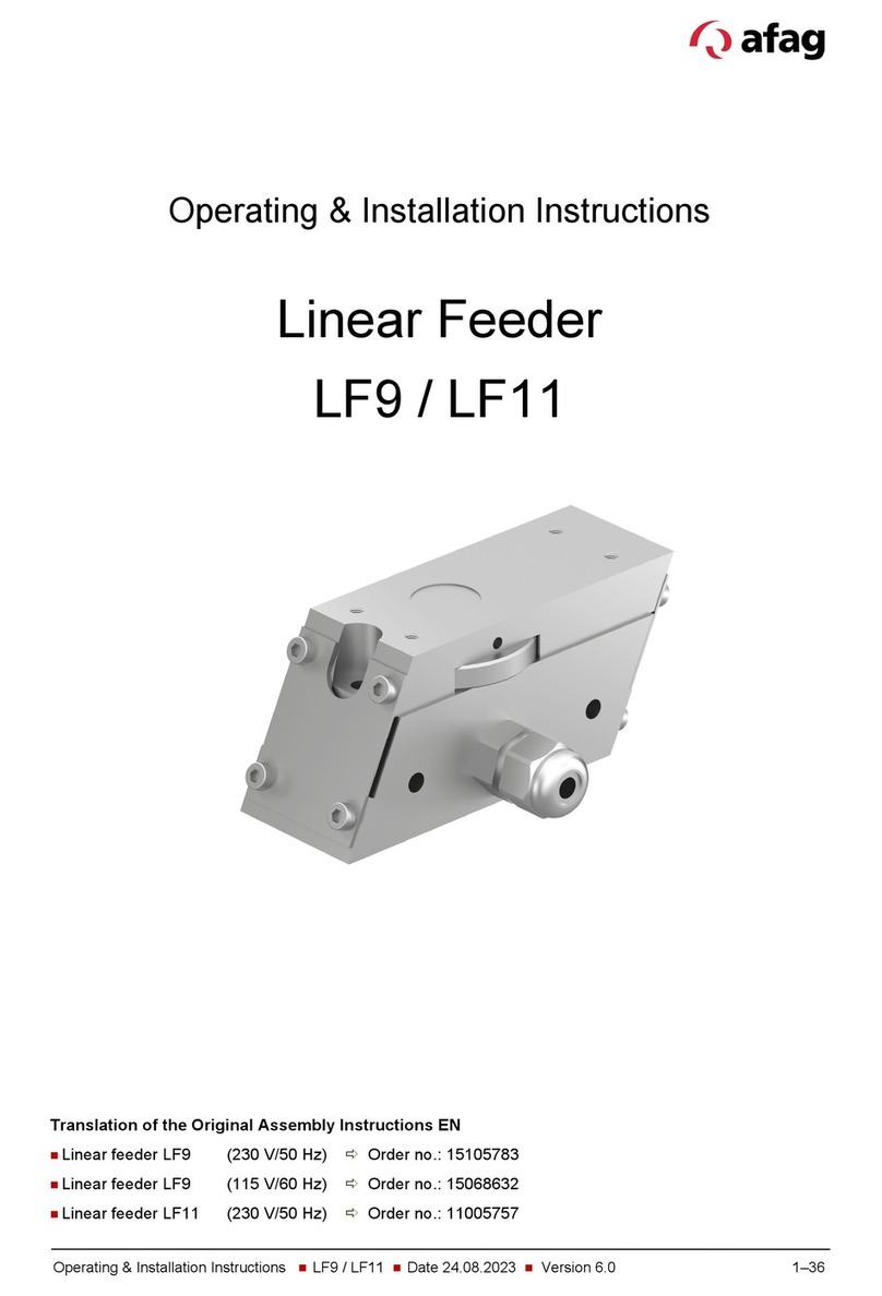
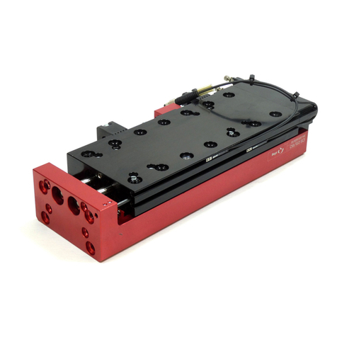
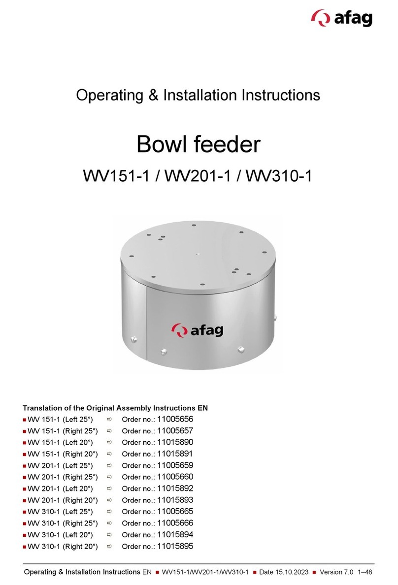
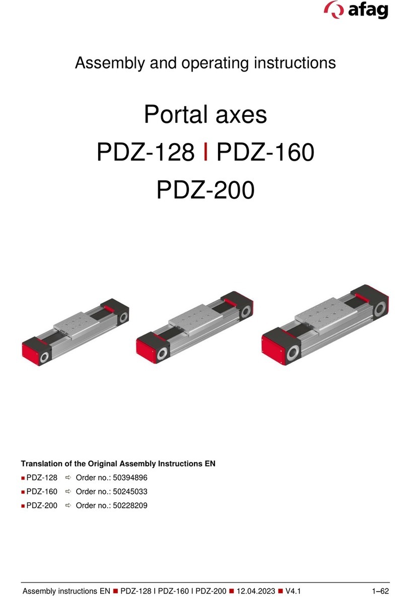
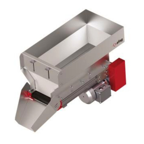
Afag IBB3.5 Product guide

Operating & Installation Instructions EN IBB3.5/IBB6/IBB12/IBB25/IBB50 Date 02.12.2023 Version 2.0 1–40
Operating & Installation Instructions
Conveyor belt hopper
IBB3.5 / IBB6 / IBB12 / IBB25 / IBB50
Translation of the Original Assembly Instructions EN
Conveyor belt hopper IBB3.5 (24VDC) Order no: 50494738
Conveyor belt hopper IBB6 (24VDC) Order no: 50494739
Conveyor belt hopper IBB12 (230 V/50 Hz) Order no: 50494740
Conveyor belt hopper IBB25 (230 V/50 Hz) Order no: 50494741
Conveyor belt hopper IBB50 (230 V/50 Hz) Order no: 50494742
Conveyor belt hopper IBB3.5 - without (24VDC) Order no: 50503689
Conveyor belt hopper IBB6 - without (24VDC) Order no: 50503690
Conveyor belt hopper IBB12 - without (230 V/50 Hz) Order no: 50503691
Conveyor belt hopper IBB25 - without (230 V/50 Hz) Order no: 50503692
Conveyor belt hopper IBB50 - without (230 V/50 Hz) Order no: 50503693
Hinged spout IBB3.5 Order no: 50503695
Hinged spout IBB6 Order no: 50503696
Hinged spout IBB12 Order no: 50503697
Hinged spout IBB25 Order no: 50503698
Hinged spout IBB50 Order no: 50503699

2 – 40 Operating & Installation Instructions EN IBB3.5/IBB6/IBB12/IBB25/IBB50 Date 02.12.2023 Version 2.0
Dear Customer
Thank you for choosing our products and placing your trust and confidence in
our company!
These operating and installation instructions contain all essential information
you need about your product. Our aim is to provide the required information as
concisely and clearly as possible. If, however, you still have any questions on
the contents or suggestions, please do not hesitate to contact us. We are always
grateful for any feedback.
Our team will also be glad to answer any further question you may have
regarding the stroke module or other options.
We wish you every success with our products!
With kind regards
Your Afag team
© Subject to modifications
The modules have been designed by Afag Automation AG according to the state
of the art. Due to the constant technical development and improvement of our
products, we reserve the right to make technical changes at any time.
Updates of our documentations
Unlike the printed documents, our digital instructions manuals, product data
sheets and catalogues are being continuously updated on our website.
Please keep in mind that the digital documents on our website are always the
latest versions.
© Copyright 2023 Afag Automation AG
All contents of the present operating and installation instructions, in particular
the texts, photographs and graphics, are protected by copyright. All rights
reserved. No part of these assembly and operating instructions may be
reproduced, distributed (made available to third parties), or transmitted in any
form or by any means, including photocopying, recording, or other electronic or
mechanical methods, without the prior written permission of Afag Automation
AG.
Afag Automation AG
Wernher-von-Braun Street 1
D-92224 Amberg (Germany)
Tel.: +49 (0) 9621 65 027-0
e-mail: sales@afag.com
Internet: www.afag.com
Afag Automation AG
Luzernstrasse 32
CH-6144 Zell (Switzerland)
Tel.: +41 62 959 86 86
e-mail: sales@afag.com
Internet: www.afag.com

Table of contents
Operating & Installation Instructions EN IBB3.5/IBB6/IBB12/IBB25/IBB50 Date 02.12.2023 Version 2.0 3–40
Table of contents
1General .................................................................................................................... 5
1.1 Contents and purpose of this manual........................................................... 5
1.2 Explanation of symbols................................................................................. 5
1.3 Additional symbols........................................................................................ 6
1.4 Warranty ....................................................................................................... 7
1.5 Liability.......................................................................................................... 7
2Safety instructions................................................................................................. 8
2.1 General ......................................................................................................... 8
2.2 Intended use ................................................................................................. 8
2.3 Foreseeable misuse ..................................................................................... 9
2.4 Obligations of the operator and the personnel ............................................. 9
2.4.1 Follow these instructions ........................................................................ 9
2.4.2 Obligations of the operating company.................................................... 9
2.4.3 Obligations of the personnel ................................................................ 10
2.5 Personnel requirements ............................................................................. 10
2.5.1 Personnel qualification ......................................................................... 10
2.6 Personal protective equipment (PPE) ........................................................ 11
2.7 Changes & Modifications............................................................................ 11
2.8 General hazards / residual risks................................................................. 11
2.8.1 General hazards at the workplace ....................................................... 11
2.8.2 Danger due to electricity ...................................................................... 13
2.8.3 Mechanical hazards ............................................................................. 13
2.8.4 Noise hazards ...................................................................................... 13
3Technical data ...................................................................................................... 14
3.1 Dimensional drawing IBB3.5 / IBB6 ........................................................... 14
3.2 Technical data IBB3.5 / IBB6 ..................................................................... 15
3.3 Dimensional drawing IBB12 / IBB25 / IBB50.............................................. 16
3.4 Technical data IBB12 / IBB25 / IBB50........................................................ 17
3.5 Accessories ................................................................................................ 17
3.5.1 Mounting parts...................................................................................... 17
3.5.2 Controller.............................................................................................. 17
4Transport, packaging and storage ..................................................................... 18
4.1 Safety instructions ...................................................................................... 18
4.2 Scope of supply .......................................................................................... 18
4.3 Transport .................................................................................................... 19
4.4 Packaging ................................................................................................... 19
4.5 Storage ....................................................................................................... 19
5Design and description ....................................................................................... 20
5.1 Structure of the conveyor belt hopper IBB ................................................. 20
Table of contents
4 – 40 Operating & Installation Instructions EN IBB3.5/IBB6/IBB12/IBB25/IBB50 Date 02.12.2023 Version 2.0
5.2 Functional description................................................................................. 20
6Installation, assembly & setting ......................................................................... 21
6.1 Safety instructions ...................................................................................... 21
6.2 Assembly .................................................................................................... 22
6.2.1 Tightening torques................................................................................ 22
6.3 Electrical connection................................................................................... 23
6.3.1 Connection of the module (control unit) ............................................... 23
6.3.2 Concluding activities ............................................................................ 24
7Operation .............................................................................................................. 25
7.1 Safety instructions ...................................................................................... 25
7.2 Commissioning ........................................................................................... 26
7.2.1 Test operation control unit.................................................................... 26
7.2.2 Preparatory activities............................................................................ 26
7.2.3 First commissioning.............................................................................. 27
7.3 Settings....................................................................................................... 27
7.3.1 Side guides........................................................................................... 27
7.3.2 Parts chute ........................................................................................... 27
7.3.3 Front panel ........................................................................................... 28
7.3.4 Belt tension........................................................................................... 28
7.4 Operation .................................................................................................... 29
8Fault elimination................................................................................................... 30
8.1 Safety instructions ...................................................................................... 30
8.2 Fault causes and remedy ........................................................................... 30
9Maintenance and repair ....................................................................................... 31
9.1 General notes ............................................................................................. 31
9.2 Safety instructions ...................................................................................... 31
9.3 Maintenance activities and maintenance intervals ..................................... 32
9.3.1 Overview of the maintenance points .................................................... 32
9.3.2 Notes on cleaning................................................................................. 33
9.3.3 Replace the conveyor belt.................................................................... 34
9.4 Further maintenance .................................................................................. 36
9.5 Spare parts, repairs .................................................................................... 36
10 Decommissioning and disposal ......................................................................... 37
10.1 Safety instructions ...................................................................................... 37
10.2 Decommissioning ....................................................................................... 37
10.3 Disposal...................................................................................................... 37

General
Operating & Installation Instructions EN IBB3.5/IBB6/IBB12/IBB25/IBB50 Date 02.12.2023 Version 2.0 5–40
1 General
1.1 Contents and purpose of this manual
These operating and installation instructions contain valuable information on
assembly, commissioning, functioning and maintenance of the conveyor belt
hopper IBB to ensure safe and efficient handling and operation.
Consistent compliance with these operating instructions will ensure:
permanent operational reliability of the module,
optimal functioning of the module,
timely detection and elimination of defects (thereby reducing maintenance
and repair costs),
prolongation of the module service life.
The illustrations in this manual shall provide you with a basic understanding of
the module and may vary from the actual design of your module.
1.2 Explanation of symbols
The safety notes are marked by a pictogram and a signal word. The safety notes
describe the extent of the hazard.
DANGER
Danger!
This safety note indicates an imminently hazardous situation which, if not
avoided, will result in death or severe injury.
WARNING
Warning!
This safety note points out a potentially hazardous situation which, if not
avoided, could result in death or severe injury.
CAUTION
Caution!
This safety note points out a potentially dangerous situation which, if not
avoided, can result in minor or slight injuries.
NOTICE
This safety note points out a potentially dangerous situation which, if not
avoided, can cause substantial damage to property and the environment.

General
6 – 40 Operating & Installation Instructions EN IBB3.5/IBB6/IBB12/IBB25/IBB50 Date 02.12.2023 Version 2.0
This note contains important additional information as well as useful tips for
safe, efficient and trouble-free operation of the module.
Further warning signs:
Where applicable, the following standardised symbols are used in this manual
to point out the various potential health risks.
Warning
- Dangerous electrical voltage.
Warning
-
Risk of hand and finger injury due to uncontrolled
movements of components.
Warning
- Magnetic field
1.3 Additional symbols
In these assembly instructions the following symbols are used to highlight
instructions, results, references, etc..
Symbol Description
1. Instructions (steps ...)
Results of actions
References to sections
Enumerations not ordered

General
Operating & Installation Instructions EN IBB3.5/IBB6/IBB12/IBB25/IBB50 Date 02.12.2023 Version 2.0 7–40
1.4 Warranty
The warranty terms for Afag handling components and handling systems are
the following:
24 months from initial operation and up to a maximum of 27 months from
delivery.
Wear parts are excluded from the warranty (The customer is entitled to a
product free of defects. This does also apply to defective accessories and
wear parts. Normal wear and tear are excluded from the warranty.
The warranty covers the replacement or repair of defective Afag parts. Further
claims are excluded.
The warranty shall expire in the following cases:
Improper use of the module.
Non-observance of the instructions regarding installation, commissioning,
operation and maintenance.
Improper assembly, commissioning, operation and maintenance.
Repairs and design changes carried out without prior technical instructions of
Afag Automation AG.
Removing the serial number from the product.
Non-observance of the EC Machinery Directive, the Accident Prevention
Regulations, the Standards of the German Electrotechnology Association
(VDE) and these safety and assembly instructions.
1.5 Liability
No changes shall be made to the modules unless described in this manual or
approved in writing by Afag.
Afag accepts no liability for unauthorized changes or improper assembly,
installation, commissioning, operation, maintenance or repair work.

Safety instructions
8 – 40 Operating & Installation Instructions EN IBB3.5/IBB6/IBB12/IBB25/IBB50 Date 02.12.2023 Version 2.0
2 Safety instructions
2.1 General
This chapter provides an overview of all important safety aspects to ensure safe
and proper use of the gripper and optimal protection of personnel.
Safe handling and trouble-free operation of the module requires knowledge of
the basic safety regulations.
Every person carrying out installation, commissioning, maintenance work or
operating the module must have read and understood the complete user
manual, especially the chapter on safety instructions.
Beyond this, there are rules and regulations regarding accident prevention that
are applicable to the place of installation which must be observed.
Failure to follow the directions and safety instructions given in this instructions
manual may result in serious hazards.
2.2 Intended use
The conveyor belt hopper is used exclusively for storing, refilling or conveying
specific product parts. These product parts must have a side length of at least
2 mm. Smaller product parts can get under the belt and lead to damage or failure
of the conveyor belt hopper.
The following uses of the modules are considered as improper use :
Fitting the belt hopper with differently shaped product parts than intended for
the belt hopper.
Equipping the belt hopper with parts that are covered with oil, grease or any
other coating.
The intended use of the module also includes:
observance of all instructions given in this manual.
compliance with the inspection and maintenance work and the
specifications in the data sheets,
using only original spare parts.

Safety instructions
Operating & Installation Instructions EN IBB3.5/IBB6/IBB12/IBB25/IBB50 Date 02.12.2023 Version 2.0 9–40
2.3 Foreseeable misuse
Any use other than or beyond the intended use described above is considered
a misuse of the module.
2.4 Obligations of the operator and the personnel
2.4.1 Follow these instructions
A basic prerequisite for safe and proper handling of modules is a good
knowledge of the basic safety instructions.
This manual, in particular the safety instructions contained therein, must be
observed by all persons working with the module.
2.4.2 Obligations of the operating company
In addition to the safety instructions given in this manual, the operating company
must comply with the safety, accident prevention and environmental protection
regulations valid for the field of application of the module.
The operating company is required to use only personnel who :
have the necessary professional qualifications and experience,
are familiar with the basic rules regarding occupational safety and accident
prevention,
have been instructed in the correct handling of the modules,
the operator of the module must draw up work instructions for handling the
product parts.
have read and understood these operating instructions.
The operating company is also required to:
monitor on an ongoing basis that the personnel work safely considering any
potential hazard involved and the assembly instructions are observed,
ensure that the assembly instructions are always kept at hand at the
installation in which the modules are mounted,
observe and communicate universally applicable laws and regulations
regarding accident prevention and environmental protection,
provide the necessary personal protective equipment (e.g., protective gloves)
and instruct the personnel to wear it.
WARNING
Risk of injury if the module is not used for its intended purpose or if it
is foreseeable used incorrectly!
The improper use of the module poses a potential hazard to the personnel.
The modules may only be used in a technically perfect condition in
accordance with its intended use and the instructions in this manual as well
as in compliance with the safety requirements!

Safety instructions
10 – 40 Operating & Installation Instructions EN IBB3.5/IBB6/IBB12/IBB25/IBB50 Date 02.12.2023 Version 2.0
2.4.3 Obligations of the personnel
All personnel working with the modules are required to:
read and observe these assembly instructions, especially the chapter on
safety,
observe the occupational safety and accident prevention regulations,
observe all safety and warning signs on the modules,
refrain from any activity that might compromise safety and health.
In addition, the personnel must wear the personal protective equipment
required for carrying out their work (chap. 2.6).
2.5 Personnel requirements
2.5.1 Personnel qualification
The activities described in the assembly instructions require specific requisites
at the level of professional qualifications of the personnel.
Personnel not having the required qualification will not be able to asses the risks
that may arise from the use of the module thus exposing himself and others to
the risk of severe injury. Therefore, only qualified personnel may be permitted
to carry out the described activities on the modules.
These operating instructions are intended for skilled personnel (installers,
system integrators, maintenance personnel, technicians), electricians and
operating personnel.
The following is a description of the professional skills (qualifications) required
for carrying out the different activities:
Qualified personnel:
Qualified personnel with appropriate training who are qualified due to their
special knowledge
and fully familiar with the machine and who have been
given instructions on how to carry out the task entrusted to them safely.
Qualified electrician:
Persons who have obtained their electrical qualifications through appropriate
professional training and complementary courses that enables them to identify
risks and prevent hazards resulting from electricity.
Operator (trained personnel):
Authorized persons
who due to their specialized professional training,
expertise and experience can identify risks and preventing hazards arising
from the use of the machine.

Safety instructions
Operating & Installation Instructions EN IBB3.5/IBB6/IBB12/IBB25/IBB50 Date 02.12.2023 Version 2.0 11–40
2.6 Personal protective equipment (PPE)
The personal protective equipment serves to protect the personnel from hazards
affecting their safety and health at work.
When working on/with the module, the personnel must use the protective
equipment assigned by the safety officer of the operating company or as
required by safety regulations. In addition, the personnel are required to:
wear the personal protective equipment provided by the operating company
(employer),
check the personal protective equipment for proper condition, and
immediately notify the person responsible on site of any defects found on the
personal protective equipment.
2.7 Changes and modifications
No changes may be made to the module which have not been described in
these operating instructions or approved in writing Afag Automation AG.
Exceptions to this are the processes described in chap. 6.2 "Assembly" and
chap. 7.3 "Settings".
Afag Automation AG accepts no liability for unauthorised changes or improper
assembly, installation, commissioning, maintenance or repair work.
The modules may not be changed or modified in any way, except with the
prior written consent of Afag.
2.8 General hazards / residual risks
Despite the safe design of the machine and the technical protective measures
taken, there remain residual risks that cannot be avoided, and which present a
non-obvious residual risk when operating the rotary modules.
Observe the safety instructions in this chapter and in the other sections of this
manual to avoid damage to property and dangerous situations for the personnel.
2.8.1 General hazards at the workplace
The modules have been built according to the state-of-the-art and the applicable
health and safety requirements. However, improper use of the module may
cause the following hazards to the personnel:
danger to life and limb of the operator or third parties,
on the modules themselves,
property damage.

Safety instructions
12 – 40 Operating & Installation Instructions EN IBB3.5/IBB6/IBB12/IBB25/IBB50 Date 02.12.2023 Version 2.0
Always keep the operating instructions ready at hand at the workplace!
Please, also observe:
the general and local regulations on accident prevention and environmental
protection,
the safety information sheet for the module.
WARNING
Danger due to missing or illegible safety instructions on the module!
Missing or illegible safety instructions can lead to dangerous situations.
The information and labelling attached to the module must be kept in a
legible condition.
Notices and labelling must not be dismounted.
After replacing cables, lines and components, all labelling on these
components must be reapplied.
WARNING
Danger due to removed or bypassed safety devices!
If safety devices are missing or bypassed, there is a risk of personal injury or
damage to property!
The safety devices on the module must not be removed or bypassed!
WARNING
Danger - Do not use in unsuitable environment !
The modules are designed for use in non-explosive atmospheres.
Do not use the modules in potentially explosive atmospheres!
CAUTION
Risk of injuries due to uncontrolled parts movements!
When operating the module uncontrolled movements may occur which can
cause personal injury or property damage.
Only qualified personnel may work with or on the module.
Read this manual carefully before carrying out any work on or with the
module.

Safety instructions
Operating & Installation Instructions EN IBB3.5/IBB6/IBB12/IBB25/IBB50 Date 02.12.2023 Version 2.0 13–40
2.8.2 Danger due to electricity
2.8.3 Mechanical hazards
2.8.4 Noise hazards
WARNING
Danger! Risk of electric shock!
If work on electrical components is required, ensure that the work is carried
out properly, failure to do so will cause serious or fatal injuries.
Work on the machine's electrical equipment may only be performed by
skilled electrician or trained personnel under the supervision of a skilled
electrician in accordance with all relevant electrical regulations.
CAUTION
Danger of body parts and clothing being pulled in!
Despite the low belt speed, the use of the appliance may pose a risk to
operating personnel due to body parts being drawn in at the points listed
below: Fastening strip conveyor belt, tilting conveyor belt, shaft conveyor belt.
Maintain a sufficient safety distance!
Never reach into the system during normal operation!
CAUTION
Noise hazards!
In certain cases, an impermissible noise level may result (e.g., when opening
the lid of the noise protection hood for filling or refilling the parts).
Wear hearing protection during noise-critical activities!

Technical data
14 – 40 Operating & Installation Instructions EN IBB3.5/IBB6/IBB12/IBB25/IBB50 Date 02.12.2023 Version 2.0
3 Technical data
3.1 Dimensional drawing IBB3.5 / IBB6
Fig. 1 Dimensional drawing IBB3.5 / IBB 6

Technical data
Operating & Installation Instructions EN IBB3.5/IBB6/IBB12/IBB25/IBB50 Date 02.12.2023 Version 2.0 15–40
3.2 Technical data IBB3.5 / IBB6

Technical data
16 – 40 Operating & Installation Instructions EN IBB3.5/IBB6/IBB12/IBB25/IBB50 Date 02.12.2023 Version 2.0
3.3 Dimensional drawing IBB12 / IBB25 / IBB50
Fig. 2 Dimensional drawing - IBB 12/ IBB 12 / IBB 25

Technical data
Operating & Installation Instructions EN IBB3.5/IBB6/IBB12/IBB25/IBB50 Date 02.12.2023 Version 2.0 17–40
3.4 Technical data IBB12 / IBB25 / IBB50
3.5 Accessories
3.5.1 Mounting parts
We do not currently offer any special peripherals for the IBB series belt hoppers.
However, you will find a wide selection of accessories for our product range in
our feeding technology components catalogue.
3.5.2 Controller
Type Power supply Order Number Note
IRG1-MS 230V/50Hz 50391018 Control with timer function via
sensors
The modules are operated in combination with an IRG1-MS control unit. Third-party control
units can also be used, provided they meet the technical conditions.
For more information on the controller, see chap. 6.3.1 and the controller manufacturer's
instructions.

Transport, packaging and storage
18 – 40 Operating & Installation Instructions EN IBB3.5/IBB6/IBB12/IBB25/IBB50 Date 02.12.2023 Version 2.0
4 Transport, packaging and storage
4.1 Safety instructions
The Afag modules are packed in the original packaging (cardboard box).
Carefully remove the module from the original packaging.
4.2 Scope of supply
The corresponding documentation is supplied with each module (e.g.,
operating and installation instructions, etc.).
Fig. 3 Scope of delivery IBB
[Unt] Designation
1 x Conveyor belt hopper IBB
1 x Operating & Installation Instructions
CAUTION
Danger of injury due to improper transport equipment!
Improper use of transport equipment can lead to injuries!
Observe transport and mounting instructions!
Use the means of transport properly!

Transport, packaging and storage
Operating & Installation Instructions EN IBB3.5/IBB6/IBB12/IBB25/IBB50 Date 02.12.2023 Version 2.0 19–40
4.3 Transport
No liability can be assumed for damages caused by improper installation on
the part of the operating company.
Please note the following for transportation:
The focus is on the middle of the module.
Pallet transport using stable transport trolleys.
The weight of the mode depends on the respective version and can be taken
from the transport documents.
4.4 Packaging
The module is transported packed on a pallet. If Afag packaging is not used, the
module must be packed in shock and dust-proof packaging.
4.5 Storage
If the module is stored for an extended period, observe the following:
Store the module in the transport packaging.
Do not store the telescope spindle axes outdoors or expose them to weather
conditions.
The storage space must be dry and dust free.
Room temperature of the storage space: 0-50 °C.
Relative air humidity: < 90% non condensing.
Protect the module from dirt and dust.
NOTICE
Risk to the environment due to incorrect disposal of the packaging
material
Environmental damage can be caused by incorrect disposal of the packaging
material.
Dispose of the packaging material in an environmentally sensitive way in
accordance with the local environmental regulations.

Design and description
20 – 40 Operating & Installation Instructions EN IBB3.5/IBB6/IBB12/IBB25/IBB50 Date 02.12.2023 Version 2.0
5 Design and description
5.1 Structure of the conveyor belt hopper IBB
The belt hopper is used exclusively for storing, refilling or conveying specific
product parts.
Fig. 4 Structure of the conveyor belt hopper IBB
Areas of application:
Parts storage for sorting and feeding devices,
Feeding of packaging systems,
Feeding of scales and counting equipment,
metered parts supply, even at manual workstations,
can be used in the food and pharmaceutical industries.
5.2 Functional description
The basis of the IBB belt hopper is a conveyor belt that transports the parts on
it onto an inclined chute.
To achieve a certain filling volume, a specific parts storage hopper is attached
to this conveyor belt.
In all sizes, the conveyor belt is driven by a DC geared motor. A three-phase
motor is used as an option.
As the DC geared motor has a preferred direction of rotation, reversing
operation of the conveyor belt by reversing the polarity of the drive voltage is
detrimental to motor service life.
However, this reversing operation is not necessary if the belt hopper is used as
intended.
Conveyor belt
Chute
Feeding bowl
Other manuals for IBB3.5
1
This manual suits for next models
19
Table of contents
Other Afag Industrial Equipment manuals

Afag
Afag CR 16-D Quick reference guide

Afag
Afag LF9 User manual

Afag
Afag CS 25/60 User manual

Afag
Afag CS 6 User manual

Afag
Afag PEZ-80 User manual

Afag
Afag RA-40-2F Series User manual

Afag
Afag HLF07-P Product guide

Afag
Afag SG-50 User manual

Afag
Afag aflex 150 qc Product guide

Afag
Afag SA-1 Series User manual
Popular Industrial Equipment manuals by other brands

LumaSense technologies
LumaSense technologies 1303 user manual

ABB
ABB HT612570 Operation manual

Siemens
Siemens MindConnect Nano quick start

Sherline Products
Sherline Products WETTROTH 8100 quick start guide

Abicor Binzel
Abicor Binzel MFS-V3 M-Drive operating instructions

Siemens
Siemens SIRIUS S2 operating instructions