Dantel 44020 User manual

CAUTION
Install or remove modules from the shelf only when the power is off.
If you install a module in the shelf with the power on, the internal
circuitry may suffer damage and the product warranty will be void.
Remove and install circuit boards only in a static-safe environment
(use antistatic wrist straps, smocks, footwear, etc.).
Keep circuit boards in their antistatic bags when they are not in use.
Do not ship or store circuit boards near strong electrostatic, electromag-
netic, magnetic, or radioactive fields.
For more complete information on electrostatic discharge safety
precautions, refer to BellcoreTM Technical Reference #TR-NWT-000870.
Copyright 1998 by Dantel, Inc. • Dantel is a registered trademark of Dantel, Inc. • ISO 9001 Registered
Printed in the U.S.A.
INSTALLATION&OPERATION MANUAL
44020-0998<90-00001>
44020 DTMF
DECODER MODULE
About this Practice:
This document has been reissued to
• Renumber figures.
Issue date: September 1998
Reissued Practices: Updated and
new content can be identified by a
banner in the right margin.
UPDATED
Table of Contents
Ordering Information ........................................................................... 2
General Description.............................................................................. 2
Circuit Description ............................................................................... 3
Application Information ....................................................................... 8
Installation.......................................................................................... 10
Operation ............................................................................................ 16
Technical Specifications ..................................................................... 17
Warranty ............................................................................................. 18

PAGE 2 44020-0998<90-00001>
ORDERING INFORMATION
The 44020 DTMF Decoder Module (Decoder Module) provides
DTMF to BCD decoding for:
♦Remote control
♦Selective signaling systems
♦DTMF to rotary converters
The Decoder Module also provides separate outputs for "*" and
"#" or A and C auxiliary functions.
The Decoder Module is a plug-in printed circuit module that fits
into any 400-type or similar equipment housing. The Decoder
Module normally functions with the following modules in
Dantels 440 Communications Management System (440 CMS):
♦44022 Subscriber Line Interface Module
♦49018 or 49028 Station Selector
♦48020 Ringing Generator
♦49020 Tone Supply
♦Use the Decoder Module with the 44023 PABX/Trunk Inter-
face Module for making a 440 CMS off-net interface assem-
bly.
♦Use the 44021 Address Decoder for 440 CMS multiple station
applications.
♦Other 440 CMS modules include the 44011 Line Interface
and the 44931 and 49031 Relay Modules.
A Decoder Module auxiliary circuit inhibits ringing generator
operation when the 440 CMS answers a station call.
Decoder Module strap options allow:
♦Input termination or bridging
♦Dial tone filter in or out
GENERAL DESCRIPTION
CONTINUED . . .
NOTE: This section lists the different options available for this product. To order any of the avail-
able options, contact Dantel Inside Sales through our toll-free number, 1-800-432-6835.
OPTION NUMBER FEATURES
A11-44020-00 DTMF (Dual Tone Multiple Frequency) Decoder
A12-49018-00 Station Selector Subassembly

44020-0998<90-00001> PAGE 3
♦Input level range setting
♦12- or 16-digit decoding
♦* and "#" or A and C auxiliary output (latching or
momentary).
The front panel includes:
♦A strobe-indicating LED
♦Test points for power supply voltages and input level
♦A subassembly panel opening
The functions of the 44020 Decoder Module can be enhanced
with a number of subassemblies:
♦The 49018 Station Selector Subassembly may be installed to
provide two address decoding for a single-station site pack-
age in the 440 system. The addresses may be used for station
call and all-call or group-call. Refer to the 49018 or 49028
practice for more information.
♦The 49020 Tone Supply Subassembly may be installed to
provide control tones for the 440 system. This subassembly is
normally used on the 44020 in a multi-station package con-
figuration. Refer to the 49020 practice for more information.
♦Other subassemblies are available as the need dictates. Con-
tact Dantel Marketing for specific information.
The 44020 DTMF Decoder Module operates on -21 to -56 VDC
input power.
GENERAL DESCRIPTION
CIRCUIT DESCRIPTION
Fig. 1 shows the 44020 DTMF Decoder Module functional
schematic. The Decoder Module consists of:
♦An input circuit
♦Buffer amplifier
♦Dial tone reject filter
♦High frequency reject filter
♦DTMF receiver and output buffers
♦# and "*" or A and C decoder and latch circuit
♦Power-up clear circuit
♦Ringing generator and control circuit
♦An internal voltage regulator

PAGE 4 44020-0998<90-00001>
FIG. 1 - FUNCTIONAL SCHEMATIC, DTMF DECODER
CIRCUIT DESCRIPTION
55
DTMF
INPUT V1
INPUT CIRCUIT
LINE
T1
DIAL TONE
REJECT
FILTER
0
-10
+10
INPUT
BUFFER AMPLIFIER
600 W
BRIG
HIGH
FREQUENCY
REJECT FILTER
J1-1
J1-2
J1-3
J1-4
DR
DR
DR
DR
DTMF RECEIVER AND OUTPUT BUFFERS
A (1)
B (2)
C (4)
D (8)
STROBE
DR STROBE
19
XTAL
-10V
-10VDC
ANALOG
IN D1
D2
D4
D8
XEN
X IN
DTMF
RECEIVER
1823
IN
X OUT
DISABLE
INPUT
D1
D2
D4
D8
DV
51
46
47
S
C
Q
LATCH
*
/#
OR
A/C
DECODER
*
A
#
C
S
C
Q
LATCH
-10VDC
43
20
18
26
27
DR
DR
DR
POWER
UP
CLEAR
FET
DRIVERS
38
*OR A
*OR A
CLEAR
# OR C
CLEAR
# OR C
POWER
UP
CLEAR
39
S
CQ
LATCH
VOLTAGE
REGULATOR
J1/1 - J1/9
J1/11
J1/10
J1/12
SUBASSEMBLY
J2/1
J2/12
13
TO RING GENERATOR ENABLE
J2
4
3
A
NORM C
B
C
D
E
RVS
4
3
FRONT PANEL
TEST POINTS
35
BCD STROBE LATCHER
AND OUTPUT TO J1
17
- BATT
(-21 to -56 VDC)
GND
14
16
15
22
24
90 SEC
RINGING GEN
CONTROL CKT LATCH
SET 1
SET 2
EXTERNAL
CLEAR
GROUP CALL
ALL CALL
49
J1-5
OUT
IN
-10VDC
DIGITS
12
16
J1-6
J1-7
J1-9
J1-8
EXT CLR
EXT CLR
#/C CLR
*/A CLR
PLS
PLS
-20VDC
-10VDC 12
1
=
GND
-10V
-20V

44020-0998<90-00001> PAGE 5
Here is a brief description of each of the functional parts of the
circuit:
Input Circuit
The DTMF input (pins 49 and 55) is a balanced 600-ohm termi-
nating or bridging port that provides DC isolation and overvolt-
age transient protection.
Transformer T1 is a high impedance bridging transformer that
provides DC isolation from the lines. Capacitor C1 blocks DC
loop current on the transformer primary.
Varistor V1 clamps any high voltage transients over 130 VAC
RMS. Zener diodes (D1 and D2) limit lower voltage transients at
about 10 VAC peak-to-peak.
Resistor R1 is strappable to provide 600-ohm line termination.
Front panel test points connect across the line.
Buffer Amplifier
The buffer amplifier provides a high impedance to the input
stage and gain adjustment for different input signal levels.
The circuit has one integrated circuit dual operational amplifier
and gain adjustment resistors.
The first operational amplifier is a noninverting voltage follower
with a very high input impedance which buffers the output.
The second operational amplifier is an inverting amplifier with
gain adjustment accomplished by strapping in feedback resistors
(10 dB gain, 0 dB gain, or 10 dB loss). The second amplifier
provides a low impedance output to the next stage.
Dial Tone Reject Filter
The dial tone reject filter is an elliptical high pass filter that
provides attenuation of 10 dB at 350 Hz and 20 dB at 440 Hz
(CCITT standard dial tone frequencies).
Dial tone tolerance reaches +20 dB (relative to the lowest DTMF
amplitude tone) in combination with the DTMF receiver IC
input. Talk-off immunity decreases because of the lost energy in
the lower frequencies.
A strap option bypasses the filter when the dial tone is either
not present or its amplitude is less than 0 dB relative to the
lower amplitude DTMF tone. Strap (out) bypasses and strap (in)
inserts the filter.
The filter is an active circuit using two operational amplifiers,
resistors, and capacitors.
CIRCUIT DESCRIPTION

PAGE 6 44020-0998<90-00001>
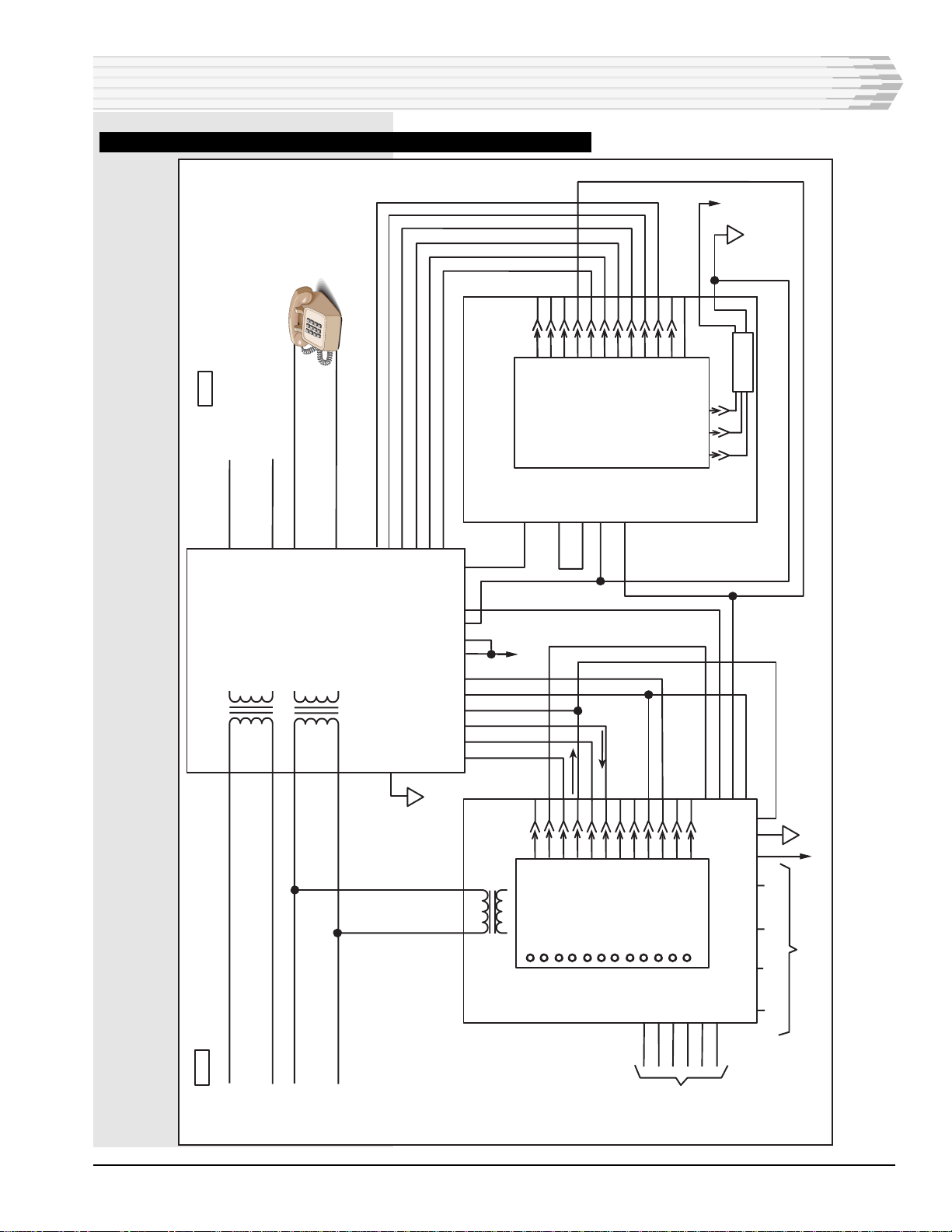
High Frequency Reject Filter
This filter is a simple RC low pass filter that rolls off 6 dB per
octave at approximately 7 kHz. This filter reduces excessive
noise above 28 kHz that could interfere with the 56 kHz internal
sampling frequency of the DTMF receiver IC .
DTMF Receiver and Output Buffers
The DTMF receiver is a monolithic CMOS integrated circuit
that combines precision active filters and analog circuits with
the control logic for decoding DTMF tones.
Upon input of a valid tone pair, the receiver verifies that the
tones are present for a minimum detection time (no greater than
40 ms). The receiver then puts out the corresponding code on the
data outputs (D1, D2, D4, and D8) and pulls the DV output high
which indicates valid data.
The DV remains high until a valid pause in the input occurs (no
greater than 40 ms). When DV goes high, a timer circuit puts a
40 ms positive pulse on the strobe output (pin 38).
The strobe output buffers through FET source followers. The DV
also drives a buffer that operates a front panel LED for visual
decoder monitoring. The data output buffers through FET
source followers to the output pins.
The DTMF receiver can be optioned for fourth-column disable
(1633 Hz). Strap 12 to disable, and strap 16 to enable. A ground
at the disable input (pin 19) inhibits decoder operation.
Auxiliary Output and Latch Circuit
The DTMF tones "*" and "#" or A and C decode separately
from the data outputs for auxiliary functions.
The selected tone pairs route through FET source followers.
When the selected code appears at the data outputs and DV
(strobe) goes high, the selected outputs become true (ground).
The outputs can be latched or remain true as long as DV re-
mains high. Clear latches with an external clear (ground) or an
opposite selected tone pair.
The FET source follower inputs can drive relay coils up to
-56 VDC at 200 mA.
Power-Up Clear
Pin 39 provides a power-up clear output. This output switches to
ground for one second when you apply power to the module. This
output clears associated subassemblies or 440 CMS modules.
Ringing Generator Control Circuit
This circuit enables the ringing generator when a phone rings in
a 440 CMS.
CIRCUIT DESCRIPTION
CONTINUED . . .

44020-0998<90-00001> PAGE 7
The circuit consists of:
♦A latch
♦A 90-second timer
♦An open collector output transistor
A ground at pin 14 or 16 from the station selector subassembly
sets the latch. The latch output at Q turns on the output transis-
tor which provides a ground at pin 13. The ground enables the
ringing generator. The latch resets when the phone answers,
either from:
♦An internal connection to the decoders on-hook off-hook
logic.
♦An external ground at pin 15.
Pin 15 wires to the 44022 Subscriber Line Interface Module
M lead output in single-station packages only.
Use the 90 second timer to sustain ringing for group call and all-
call circuits. A ground at pin 22 or 24 from the group call or all-
call circuit starts the timer. The timer holds the output transis-
tor on for 90 seconds or until you reset the timer.
Internal Voltage Regulator
The internal voltage regulator regulates battery voltage from
-21 to -56 VDC to internal levels of -21 and -10 VDC. These two
voltages apply to an on-board connector that powers the 49018
or 49028 Station Selector.
The regulator consists of simple series pass transistors with
zener voltage regulation.
CIRCUIT DESCRIPTION

PAGE 8 44020-0998<90-00001>
The primary application of the 44020 DTMF Decoder Module
is with the 440 Communication Managment System. The 440
CMS, Decoder Module, associated subassemblies and 440 CMS
modules provide a station-calling facility.
Fig. 2 shows a typical 440 CMS single-station package. Associated
modules include:
♦The 44022 Subscriber Line Interface Module
♦The 48020 Ringing Generator
Subassemblies shown are:
♦The 49018 Station Selector Subassembly
♦The 49020 Tone Supply
You can use the Decoder Module in multi-station packages as
described in the Dantel 440 Communication Management System
documentation. The Decoder Module drives multiple address
modules or other devices up to its 200 mA current capacity.
You can also use the Decoder Module with no subassemblies when
you require a BDC output from decoded dialing tones.
APPLICATION INFORMATION

44020-0998<90-00001> PAGE 9
FIG.2-440COMMUNICATION MANAGEMENT SYSTEMAPPLICATION BLOCK DIAGRAM
41
44022
STATION
INTERFACE
4
600 Ω
600 Ω
XMT
RCV
12
11
10
9
8
7
5
6
4
3
2
1
P2 / J2
35
17 -24 OR -48 VDC
GND
10 11 12
P1 / J1
49020
TONE SUPPLY
SUBASSEMBLY
VDC VDC GND
REGULATOR
48020
RING
GENERATOR
7
13
51
53
38
40
36
34
32
30
4W RCV
4W XMT OR 2W XMT/RCV
2 WIRE
OFF HOOK
#
ON HOOK
*
BUSY TONE
RING BACK TONE
ALERT TONE
RING INTERRUPT
RING
GEN
SUPPLY
31
RING GEN
SUPPLY
23
43
21
19
RING GEN ENABLE
12
11
10
9
8
7
5
6
4
3
2
1
16
15
13
22
16
55 322 39 26 24 35 23 2125 31
RING
START
PWR UP CLR
STATION OUTPUT
GP CALL
DIGIT 0
DIGIT 1
BUSY
RESET
CLR
PWR-UP
BUSY
49
P2
P1
12
11
10
8
7
5
6
4
3
2
1
9
GND
-20
-10
STROBE
D
C
B
A
49018
STATION
SELECTION
44020
DTMF DECODER
20 18 27 26 35 17 39
* OR A * OR A # OR A # OR A
OUTPUT CLR EXT OUTPUT EXT CLR
-21/-56 V
GND
46
19
51
47
43
38
DISABLE
INPUT
A
B
C
D
STROBE
N/A
N/A
47
2
17
M LEAD
-21/-56
VDC
-10 -20
LINE DROP
APPLICATION INFORMATION

PAGE 10 44020-0998<90-00001>
INSTALLATION
I
nstallation consists of setting the straps, wiring the connector,
mounting the module in the shelf and checking out the module.
1. Install the proper strap options.
Refer to Fig. 3 and Table A.
FIG. 3 - 44020 DTMF DECODER STRAP OPTION LOCATIONS
NOTE: The straps depicted in Fig. 2 are examples only. Strap each
module per usage desired. Refer to Table A.
A
B
C
D
E
NORMAL
REVERSE
1
12
J1
1
12
J2
C2
#2
A2
2
C1
#1
A1
1
16
DGT
12
0DB
+10DB
-10DB
IN
DTF
OUT
BRDG
600 OHM
OR A # OR CCLR
EXT
CLR
PLS EXT
CLR

44020-0998<90-00001> PAGE 11
STRAP OPTIONS
Input Termination
Strappable for bridging or 600-ohm termination.
Input Level
Three ranges of input level can be used:
♦High levels of -10 dBm to +10 dBm
♦Medium levels of -20 dBm to 0 dBm
♦Low levels of -30 dBm to -10 dBm
No other level control is provided
Dial Tone Filter
Strapped in when used in systems with CCITT standard tone (350
Hz and 440 Hz). Strap out when dial tone is not used.
Fourth Column Tones
Strap for 16-digit dialing if fourth column tones are used in the
system. Strap for 12-digit dialing otherwise.
Auxiliary Outputs
Two auxiliary outputs are provided for various control applica-
tions. They are used for privacy functions in the 440 system. The
outputs can be strapped to be activated by the "*" and "#" tones or
by the A and C tones.
Latching Mode
The auxiliary outputs can be strapped for three modes of latching:
♦Non-latching.
♦Latching that is cleared by a contact to ground.
♦Latching that is cleared upon receipt of the opposite tone
(* clears "#" and "#" clears "*" or A clears C and C clears
A).
INSTALLATION

PAGE 12 44020-0998<90-00001>
TABLE A - 44020 DTMF DECODER STRAP OPTIONS
OPTION
INPUT
600 Ohms
Bridging
INPUT LEVEL
+10 to -10 dBm
0 to -20 dBm
-10 to -30 dBm
DIAL TONE FILTER
In
Out
DIALING
12-Digit
16-Digit
AUXILIARY OUTPUTS
* and #
A and C
* AND A LATCHING
* or A Nonlatching
* or A externally cleared
* or A cleared by # or C
# AND C LATCHING
# or C Nonlatching
# or C externally cleared
# or C cleared by * or A
INSTALL JUMPER
600 ohms
BRDG
-10
0
+10
DTF IN
DTF OUT
12 DGT
16 DGT
*1, *2, #1, #2
A1, C1, A2, C2
PLS
EXT CLR
# or C CLR
PLS
EXT CLR
* or A CLR
2. Wire the connector.
If you wire the connector, refer to Fig. 4 for the module connector
pin wiring assignments. Normally the shelf slot is prewired.
3. Mount the module in the equipment shelf.
Slide the module along the guide slots then firmly seat the edge
connector in its receptacle.
4. Check out the module.
Refer to Table B for checkout procedures. Refer to Table C for
decoder output logic.
Use the following test equipment for module checkout:
♦AC/DC Multimeter (Weston Model 666 or similar
equipment)
♦DTMF Pad, which can be located anywhere in the
communications system if it can transmit a signal
♦Extender Card, 400 type with 56-pin edge connector (Dantel
Part Number A15-00440-00)
INSTALLATION
44020-00
DTMF
DECODER
-10V GND -20V
INPUT LEVEL
A11-44020-00 REV__
STROBE
CKT 1
CKT 2
O/1
STATION
SELECTOR
49018-00

44020-0998<90-00001> PAGE 13
56 55
54 53
52 51
50 49
48 47
46 45
44 43
42 41
40 39
38 37
36 35
34 33
32 31
30 29
28 27
26 25
24 23
22 21
20 19
18 17
16 15
14 13
12 11
10 9
87
65
43
21
CIRCUIT SIDE
OF PC BOARD
COMPONENT SIDE
OF PC BOARD
DTMF Input
B (2)
DTMF Input
C (4)
A (1)
D (8)
Power-Up Clear Ouput
Strobe Output
-Battery (-21 to -56VDC)
# or C Output
# or C Clear Output
All Call **
Group Call **
Disable Input* or A Output
Ground* or AClear Input
External Clear **Ring Enable 1 **
Ring Start **Ring Enable 2 **
Subassembly Connections
(function depends on
subassembly used)
INSTALLATION
Subassembly Connections
(function depends on
subassembly used)
** Ring Start Control Circuit
FIG. 4 - 44020 DTMF DECODER MODULE PIN DESIGNATIONS

PAGE 14 44020-0998<90-00001>
CONTINUED . . .
ACTION
Plug in module and apply power.
Set a multimeter on DC and connect leads to front
panel GND and -20 V test points.
Move multimeter leads to front panel GND and
-10 V test points.
Set multimeter on AC and connect to front panel
INPUT LEVEL test points.
Apply a DTMF tone to the input by operating a
touch pad somewhere in the system. The touch pad
can be connected at the front panel INPUT LEVEL
test points, but the decoder does not provide talk
battery at these points.
Repeatedly apply DTMF tones.
Make the following check if the decoder output is
connected to a following BCD input device, such
as a 49018 Station Selector Subassembly or a 44021
Address Decoder:
Clear the decoder by applicable means.
(This depends on the system strapping
requirements.)
Dial an address code that is valid for the
BCD input device.
Clear the decoder
Make the following check if the decoder output is
not connected to a following BCD input device, or if
the following device is not functional:
Install the module in an extender card.
Set the multimeter on DC and connect the
ground (+) lead to the front panel GND test
point. Connect a 100Kohm resistor from the
front panel -10V test point to the negative
probe.
Connect the negative probe of the meter to pin
46, of the edge connector.
Dial digit 1, 3 or any digit that produces a 1
at the A output. (Refer to Table C.)
Move the negative probe to pin 51.
Dial digit 2, 3, etc. to check the B output.
Move the negative probe to pin 47.
Dial digit 4, 5, etc. to check the C output.
Move the negative probe to pin 43.
Dial digit 8, 9, etc. to check the D output.
RESULTS
No visible indication.
Read -20 + 3 VDC
Read -10 + 1.5 VDC
Read a level between -30 dBm and
+10 dBm. Verify the proper input
level range strapping per Table A.
Verify operation of STROBE LED.
BCD input device gives valid code
response.
BCD input device returns to normal.
Read -10VDC
Read -10 VDC
Read 0 VDC
Read -10 VDC
Read 0 VDC
Read -10 VDC
Read 0 VDC
Read -10 VDC
Read 0 VDC
STEP
1
2
3
4
5
6
7
8
INSTALLATION
TABLE B - 44020 DTMF DECODER CHECKOUT PROCEDURE

44020-0998<90-00001> PAGE 15
ACTION
Make the following check if it is desired to confirm
the operation of the auxiliary outputs:
Leave the module in the extender card and the
positive lead of the meter in the GND test
point. Leave the resister connected between
the -10V test point and the negative probe.
Clear the decoder (if strapped for latching).
Connect the negative probe to pin 20.
Dial * digit (or A, if so strapped).
Clear the decoder (if strapped for latching).
Move negative probe to pin 27.
Dial # digit (or C, if so strapped).
Clear the decoder (if strapped for latching).
Make the following check if it is desired to confirm
the operation of the power-up clear output:
Leave the module in the extender card and the
positive lead of the meter in the GND test
point.
Connect the negative probe to pin 39.
Remove power from the module and reapply.
End of test. Remove meter and extender card.
RESULTS
Read -10 VDC
Read -10 VDC
Read 0 VDC (remains, if strapped
for latching)
Read -10 VDC
Read 0 VDC (remains, if strapped
for latching)
Read -10 VDC
Read 0 VDC for approximately one
second after power is applied.
STEP
9
10
11
INSTALLATION
TABLE B (CONTINUED) - 44020 DTMF DECODER CHECKOUT PROCEDURE
TABLE C - DTMF FREQUENCIES AND BCD OUTPUT CODES
INPUT DTMF CODE FREQUENCIES (HZ) OUPUTS
LOWER
697
697
697
770
770
770
851
851
851
941
941
941
697
770
851
941
UPPER
1209
1336
1477
1209
1336
1477
1209
1336
1477
1336
1209
1477
1633
1633
1633
1633
D
0
0
0
0
0
0
0
1
1
1
1
1
1
1
1
0
C
0
0
0
1
1
1
1
0
0
0
0
1
1
1
1
0
B
0
1
1
0
0
1
1
0
0
1
1
0
0
1
1
0
A
1
0
1
0
1
0
1
0
1
0
1
0
1
0
1
0
1
2
3
4
5
6
7
8
9
0
*
#
A (4th column)
B (4th column)
C (4th column)
D (4th column)

PAGE 16 44020-0998<90-00001>
The 44020 DTMF Decoder Module operates when you apply
power. Operation of the Decoder Module consists of observ-
ing the STROBE LED on the front panel which flashes when the
Decoder Module decodes a digit.
OPERATION

44020-0998<90-00001> PAGE 17
TECHNICAL SPECIFICATIONS
DESCRIPTION
Input Impedance
Input Type
Input Level Range
Maximum Input Voltage
Input Filter
DTMF Receiver Characteristics
Frequency Detect Bandwidth
Minimum Acceptable Twist
Detection Time
Pause Time
60 Hz Tolerance w/ Filter
60 Hz Tolerance w/o Filter
(referenced to lower level tone)
Noise Tolerance (Mitel Tape CM7290)
(referenced to lower level tone)
BCD Outputs
Logic
BCD Duration
Strobe Pulse Duration
BCD Terminals
Maximum Output Current
Maximum External Source Voltage on Output
Auxiliary Outputs
Auxiliary Terminals
Maximum Output Current
Maximum External Source Voltage on Output
Nonlatching
Latching
Clear
External Clear Input
Power-up Clear Output
Maximum Output Current
Maximum External Source Voltage on Output
Power Output to Piggy-back Subassembly
Input Voltage Range
Input Power Requirements
Idle
Full Load
Heat Dissipation
Idle
Full Load
Physical Dimensions
Weight
Operating Temperature Range
VALUE
600 ohms or Bridging (>10K ohms)
Transformer Coupled, DC Blocked
-30 dBm to +10 dBm
130 VAC
Dial Tone Reject (strap option)
Minimum Typical Maximum
+(1.5%+2Hz) +2% +3%
-8 dB --- +4 dB
20ms 25ms 40ms
25ms 32ms 40ms
--- --- +20 dB
--- --- 0 dB
--- --- -12 dB
A, B, C, D plus Strobe
Modified Hexadecimal 12- or 16-digit BCD
(Compatible w/ 44021 & 49018 Station Selectors)
As long as key is pressed
40ms Nominal
Buffered w/ open emitter driver, switched to GND
200 mA
-56 VDC
* and # or A and C
Buffered w/ open emitter driver, switched to GND
200ms
-56 VDC
Strappable. Outputs operated for duration of tone
Strappable. Outputs operated until cleared
Strappable to clear by external contact or on re-
ceiving opposite auxiliary tone. (* clears #, #
clears * or A clears C, C clears A)
Ground to clear, open normal
Buffered with open emitter driver, switching to
ground for 1 second on power-up
200 mA
-56 VDC
-10 VDC @ 100 mA
-20 VDC @ 30 mA
-21 VDC to -56 VDC
34 mA @ -21 to -56 VDC
38 mA @ -21 to -56 VDC
2.4 to 6.5 BTU/Hr @ -21 to -56 VDC
2.7 to 7.3 BTU/Hr @ -21 to -56 VDC
1.4" x 6.0" x 5.6"
6 oz.
0° C. to 60 ° C.

PAGE 18
18 PAGES 44020-0998<90-00001>
LIMITED WARRANTY
The Seller warrants that the standard hardware products sold will be free from defects in material and
workmanship and perform to the Sellers applicable published specifications for a period of 18 months for
hardware, and 3 months for software, from the date of the original invoice. The liability of the Seller hereunder
shall be limited to replacing or repairing, at its option, any defective products which are returned F.O.B. to the
Sellers plant, (or, at the Sellers option, refunding the purchase price of such products). In no case are products
to be returned without first obtaining permission and a customer return authorization number from the Seller.
In no event shall the Seller be liable for any consequential or incidental damages.
Equipment or parts which have been subject to abuse, misuse, accident, alteration, neglect, unauthorized
repair or installation are not covered by warranty. The Seller shall make the final determination as to the
existence and cause of any alleged defect. No warranty is made with respect to custom equipment or products
produced to the Buyers specifications except as specifically stated in writing by the Seller in the contract for
such custom equipment.
This warranty is the only warranty made by the Seller with respect to the goods delivered hereunder, and may
be modified or amended only by a written instrument signed by a duly authorized officer of the Seller and
accepted by the Buyer.
Warranty and remedies on products not manufactured by the Seller are in accordance with warranty of the
respective manufacturer. THE SELLER MAKES NO OTHER WARRANTY OF ANY KIND WHATSOEVER,
EXPRESSED OR IMPLIED; AND ALL IMPLIED WARRANTY OF FITNESS FOR A PARTICULAR PUR-
POSE WHICH EXCEEDS THE AFORESAID OBLIGATIONS IS HEREBY DISCLAIMED BY THE SELLER.
INCASE OF DIFFICULTY
If you experience difficulty with this equipment, check the following, as appropriate:
1. Switch settings
2. Signal levels
3. Software configuration
4. Connections between Dantel’s equipment and your equipment.
If there is still a problem, substitute equipment that is known to be good. For additional assistance, call
Dantels Technical Field Service Department weekdays, 6 A.M. to 5 P.M. pacific time:
1-800-4DANTEL (1-800-432-6835).
If a thorough checkout shows a piece of equipment has malfunctioned, you may return it to the factory. For
repairs and emergency replacements, obtain a Return Material Authorization (RMA) number from the Cus-
tomer Service Representative at 1-800-4DANTEL (1-800-432-6835).
To ensure expedient processing of your order, provide a purchase order number and shipping and billing
information when requesting an RMA number. Also, when the units are returned to Dantel, include a descrip-
tion of the failure symptoms for each unit returned. Send defective equipment to:
Dantel, Inc. • 2991 North Argyle Avenue • Fresno, California 93727-1388
P.O. Box 55013 • Fresno, CA 93747-5013 Phone (209) 292-1111 Fax (209) 292-9355 http://www.dantel.com
WARRANTY
This manual suits for next models
1
Other Dantel Media Converter manuals
Popular Media Converter manuals by other brands

Crystal Vision
Crystal Vision Indigo DACA214 user manual

RONK
RONK ECONO-PHASE Series Getting started

Tiernan
Tiernan TE3000 Installation and operation guide

Quick
Quick RCV WI RF Manual of use and maintenance

Linear Technology
Linear Technology DC1739B-C Demo Manual

Samlex Europe
Samlex Europe IDC360iM 1224 V 2.0 owner's manual