PAGE 10 46035-01-1297<90-00071>
2. Install a subassembly, if necessary.
To install or change a subassembly, follow these steps:
1. If there is a hole plug in the front panel of the module, remove the
plug.
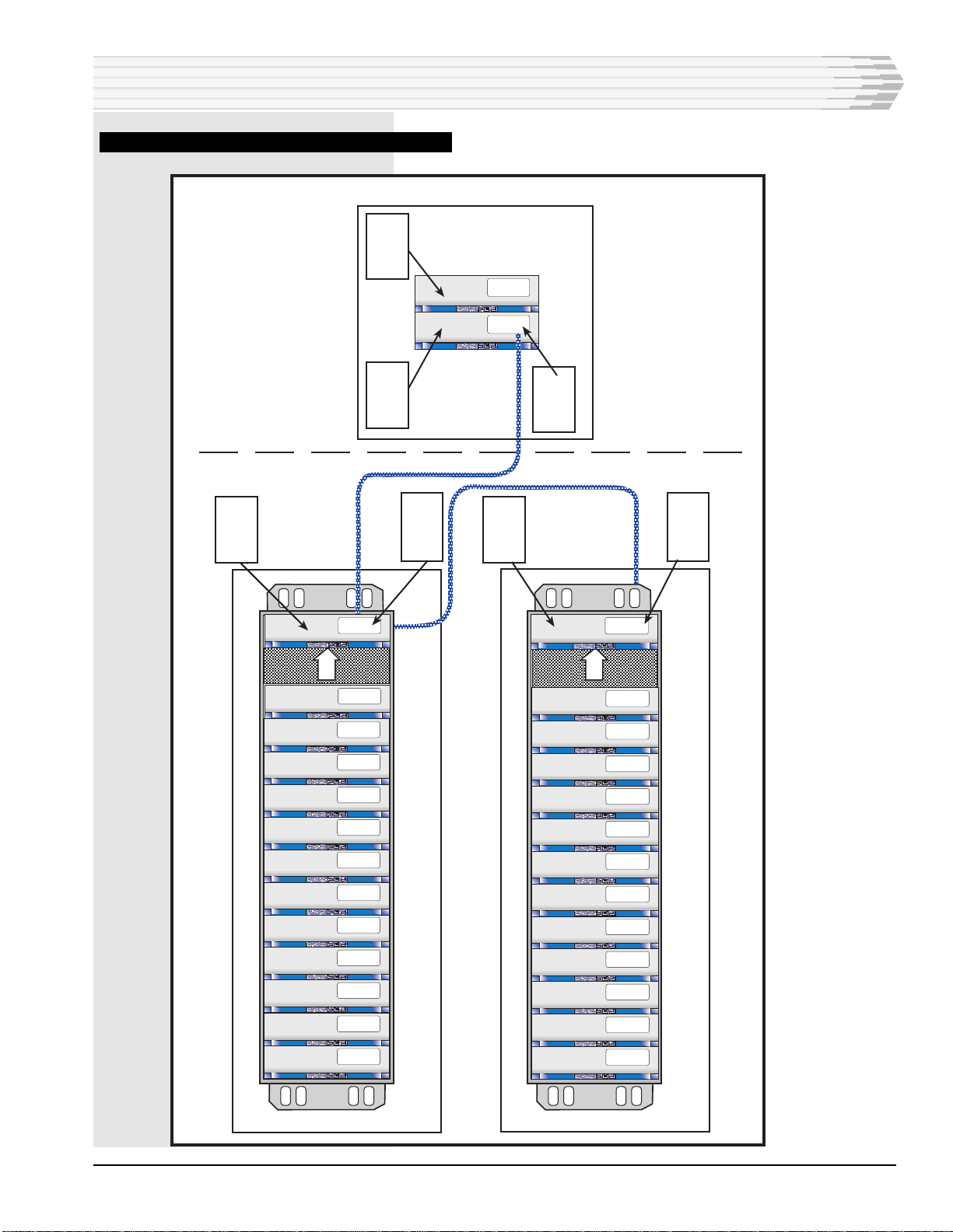
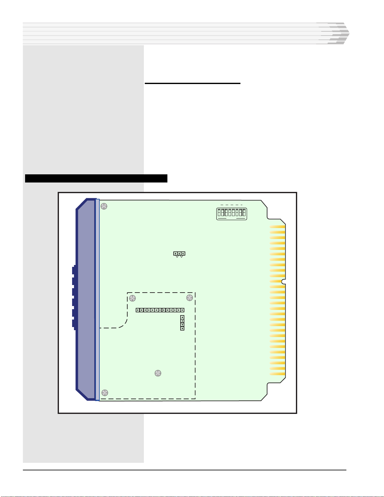
2. Remove the three screws from the subassembly standoffs (refer to
Fig. 6).
3. Take the subassembly off the board.
4. Place the new subassembly on the board:
♦Insert P4 into J4 and P5 into J5.
♦Make sure each connector pin goes straight into the socket.
♦Make sure the subassembly fits closely on the standoffs.
5. The front panel of the subassembly should be straight in the open-
ing in the front panel of the module.
6. Replace the three screws in the standoffs.
Refer to the subassembly manual for strapping information.
3. Install the module in the proper slot in the equipment
shelf.
In most cases, the shelf will be pre-wired for the 46035 Con-
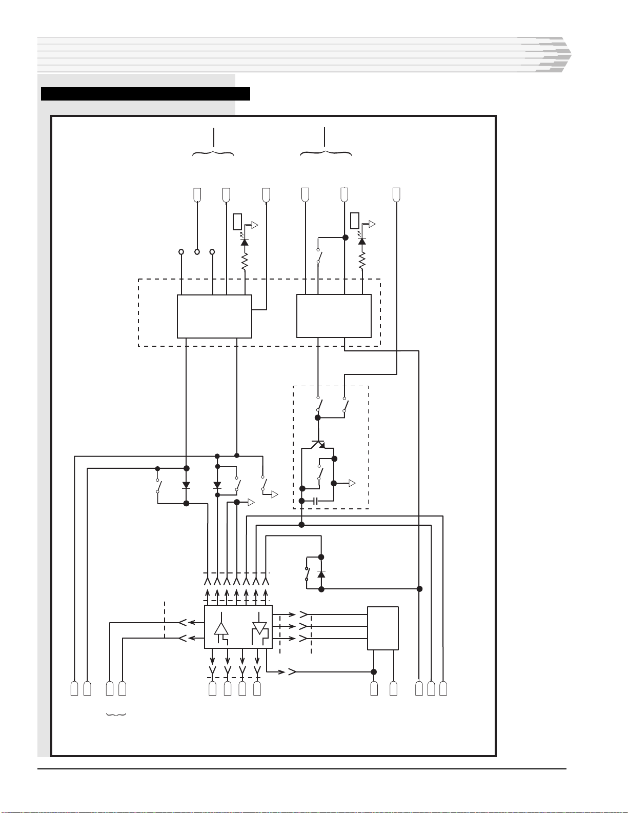
verter Module. If necessary, refer to Fig. 7 for module pin
designations.
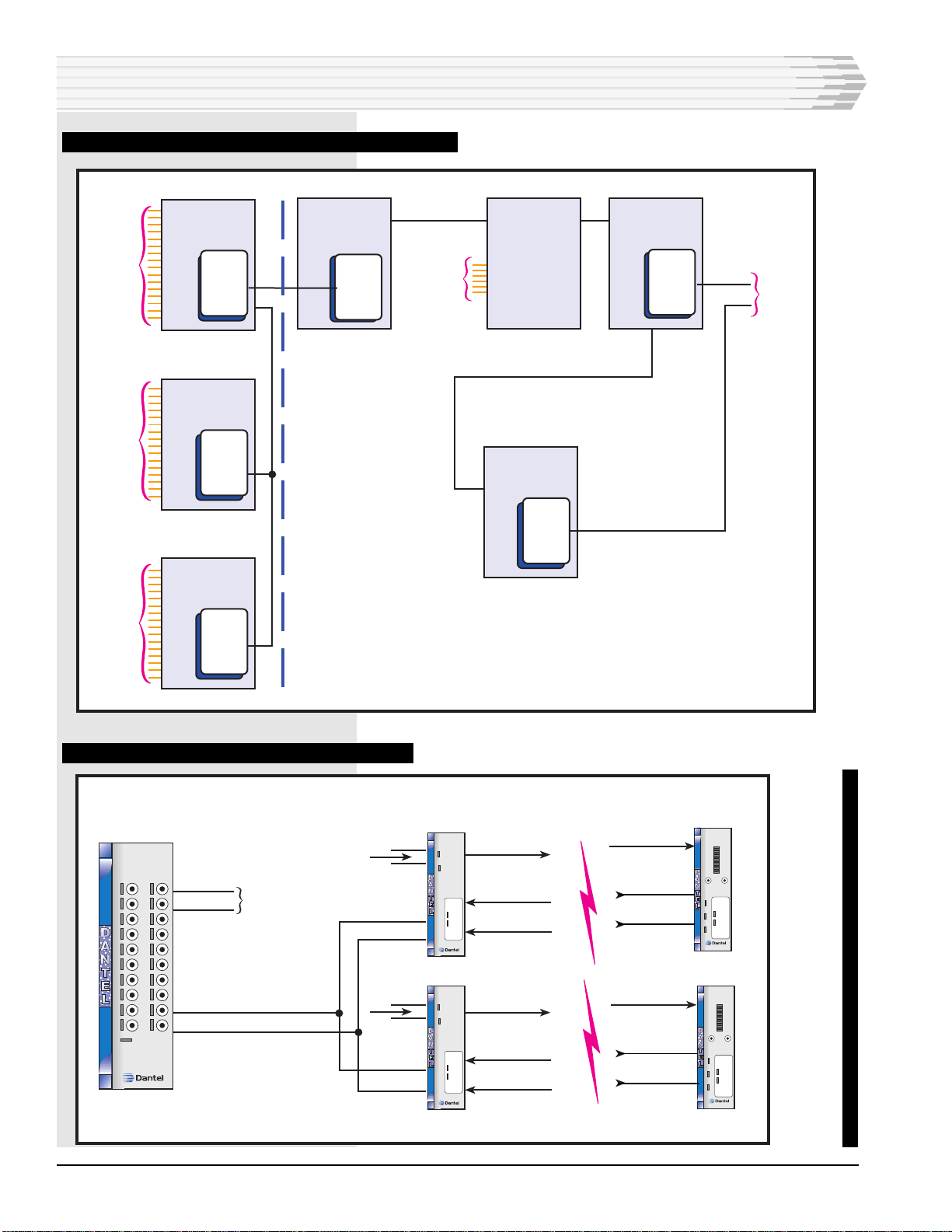
4. Align the modem subassembly, if installed:
The modem must be connected to another modem at the other
end of the communications line.
1. Apply power.
2. Place the front panel switch in the TEST position.
3. Verify that the front panel CD (Carrier Detect) LED at the distant
end indicates data transmisssion activity.
4. With a dB meter (bridging), check the signal level at the XMT test
points. Adjust the XMT LVL to obtain the level required for your
application.
5. With a dB meter (bridging), check the incoming signal level at the
RCV test points. The signal level should be 0 to
-40 dBm, depending on your application. There is no field adjust-
ment for this circuit.
5. Checkout
Checkout consists of monitoring the unit’s front panel LEDs to
verify data is being transmitted and received.
INSTALLATION