Dantel A18-05774 Series User manual

CAUTION
•Install or remove modules from the shelf only when the power is off.
If you install a module in the shelf with the power on, the internal
circuitry may suffer damage and the product warranty will be void.
•Remove and install circuit boards only in a static-safe environment
(use antistatic wrist straps, smocks, footwear, etc.).
•Keep circuit boards in their antistatic bags when they are not in use.
•Do not ship or store circuit boards near strong electrostatic, electromag-
netic, magnetic, or radioactive fields.
•For more complete information on electrostatic discharge safety
precautions, refer to BellcoreTM Technical Reference # TR-NWT-000870.
Copyright 1998 by Dantel, Inc. • Dantel is a registered trademark of Dantel, Inc. • ISO 9001 Registered
Printed in the U.S.A.
INSTALLATION & OPERATION MANUAL
05774-0598 <90-00122>
A18-05774-XX
VNET/ORDER WIRE
INTERFACE SHELF
About this Practice:
This practice has been reissued to:
• This is a new document.
Issue date: May 1998
Reissued Practices: Updated and
new content can be identified by a
banner in the right margin.
UPDATED
Table of Contents
Ordering Information ........................................................................... 2
General Description.............................................................................. 2
Installation............................................................................................ 3
Operation ............................................................................................ 11
Technical Specifications ..................................................................... 13
Warranty ............................................................................................. 14
A11-44020-00 REV__
STROBE
CKT 2
O/1
CKT 2
O/1
A11-44118-00
44118-00
DISTRIBUTION
BRIDGE
LINE RCV
PORT 1
PORT 2
PORT 3
PORT 4
COMBINED
DIST
OUTPUT
PORT 1
PORT 2
PORT 3
PORT 4
LINE XMT
44118-00 REV__
44020-00
DTMF
DECODER
-10V GND -20V
INPUT LEVEL
449018-00
CKT2
CKT 1
O/I
STATION
SELECTOR
A11-44020-00REV__
44931-00
RELAY TIMER
A11-44931-00 REV__
TIMER A
RELAY A
TIMER B
RELAY B
449018-00
Relay C
Timer C
O/C
STATION
SELECTOR

PAGE 2 05774-0598 <90-00122>
NOTE: This section lists the different options available for this product. To order any of the avail-
able options, contact Dantel Inside Sales through our toll-free number, 1-800-432-6835.
OPTION NUMBER FEATURES
A18-05774-00 Wired only. No modules.
A18-05774-01 Equipped VNET Interface Shelf
ORDERING INFORMATION
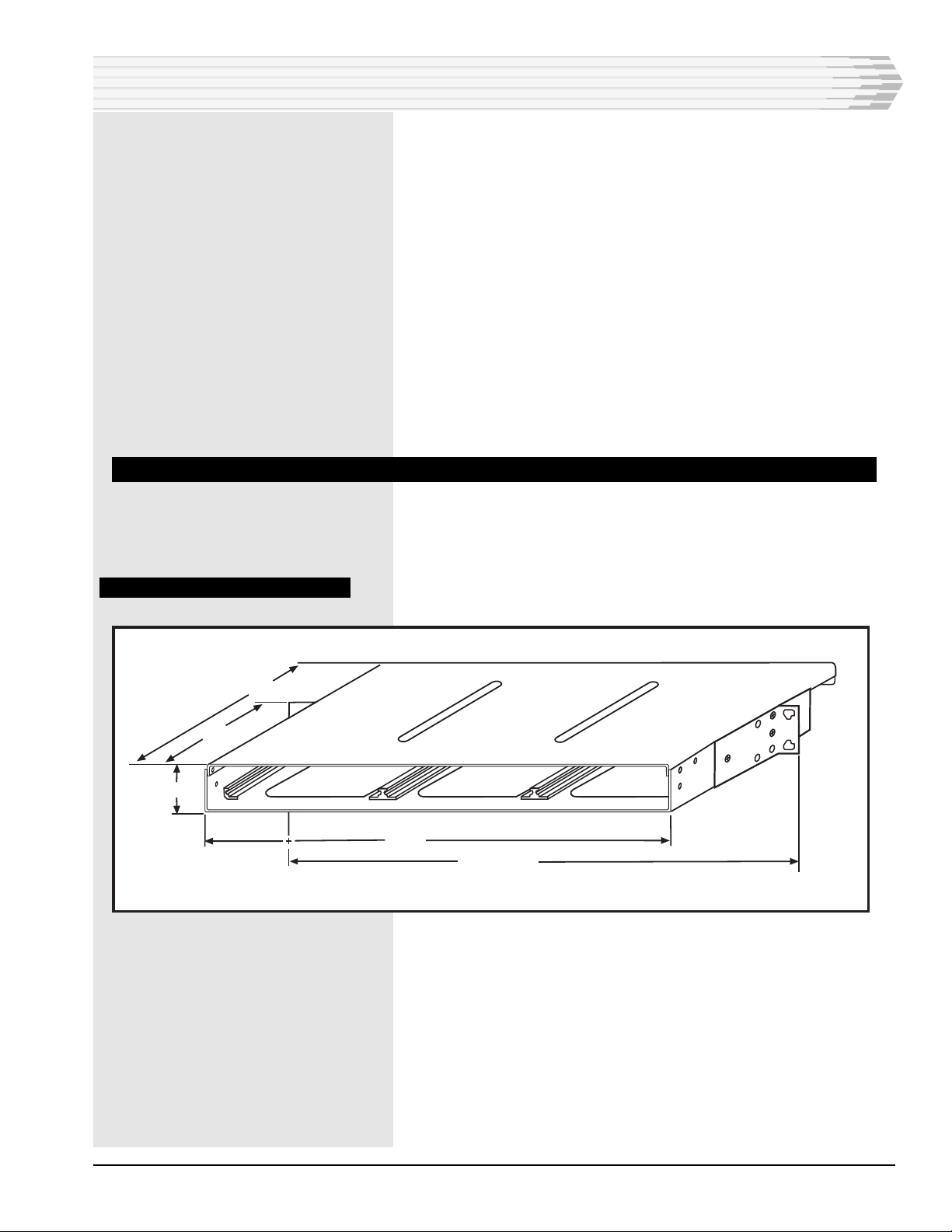
GENERAL DESCRIPTION
This unit is designed to be a 4 wire, DTMF controlled PBX
interface that will output battery or ground on its M lead and
it will accept battery or ground on its E lead depending upon the
user’s requirements.
The unit is designed so that the caller, from the PBX side, will
shout down to the desired remote after the VNET interface has
been accessed. No DTMF signaling to the remote Order Wire
stations will be used. The DTMF signaling is only used to get
access for the order wire to the PBX.
The user calling from the order wire side of the system will dial
3 digits plus “*” to gain access to the order wire. The same 3
digits plus “#” will release the system. Either party hanging up
will release the system. The unit will operate from -21 to -56
volts with levels of +7 to -16 dBm on any port, using the Dantel
44118 VF bridge. In this application, port 4 (which is used for
PBX acces) will be set for -6dBm on the RX input and 0dBm on
the TX output. All other ports will be used for the order wire and
will be +7 dBm on the RX and -16 dBm on the TX.
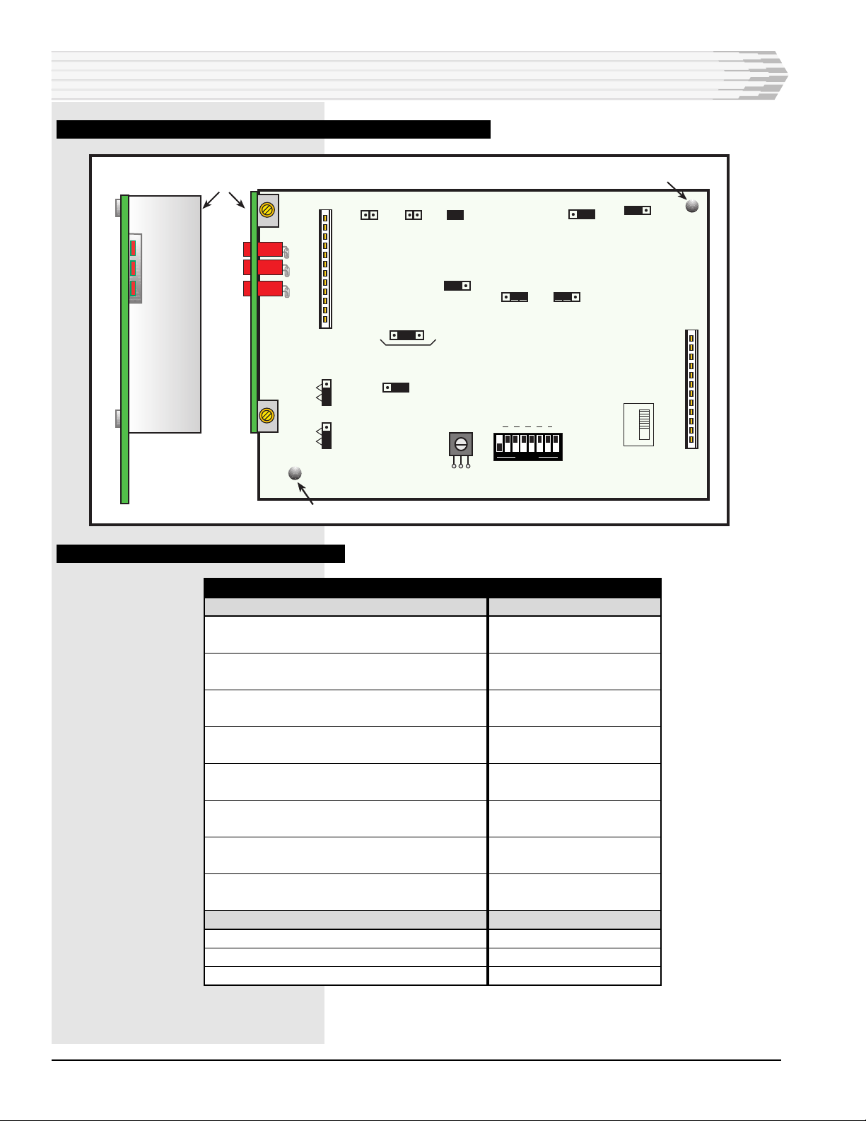
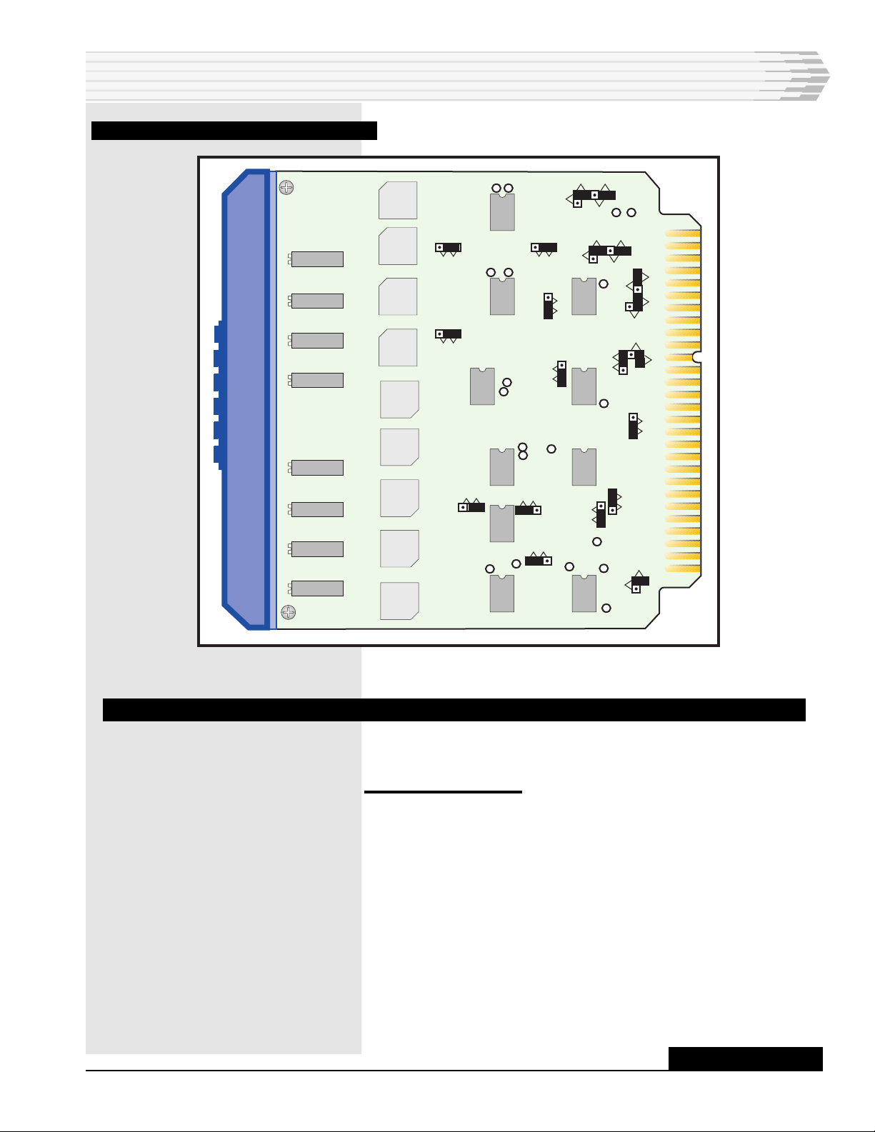
The OW interface will be made up of:
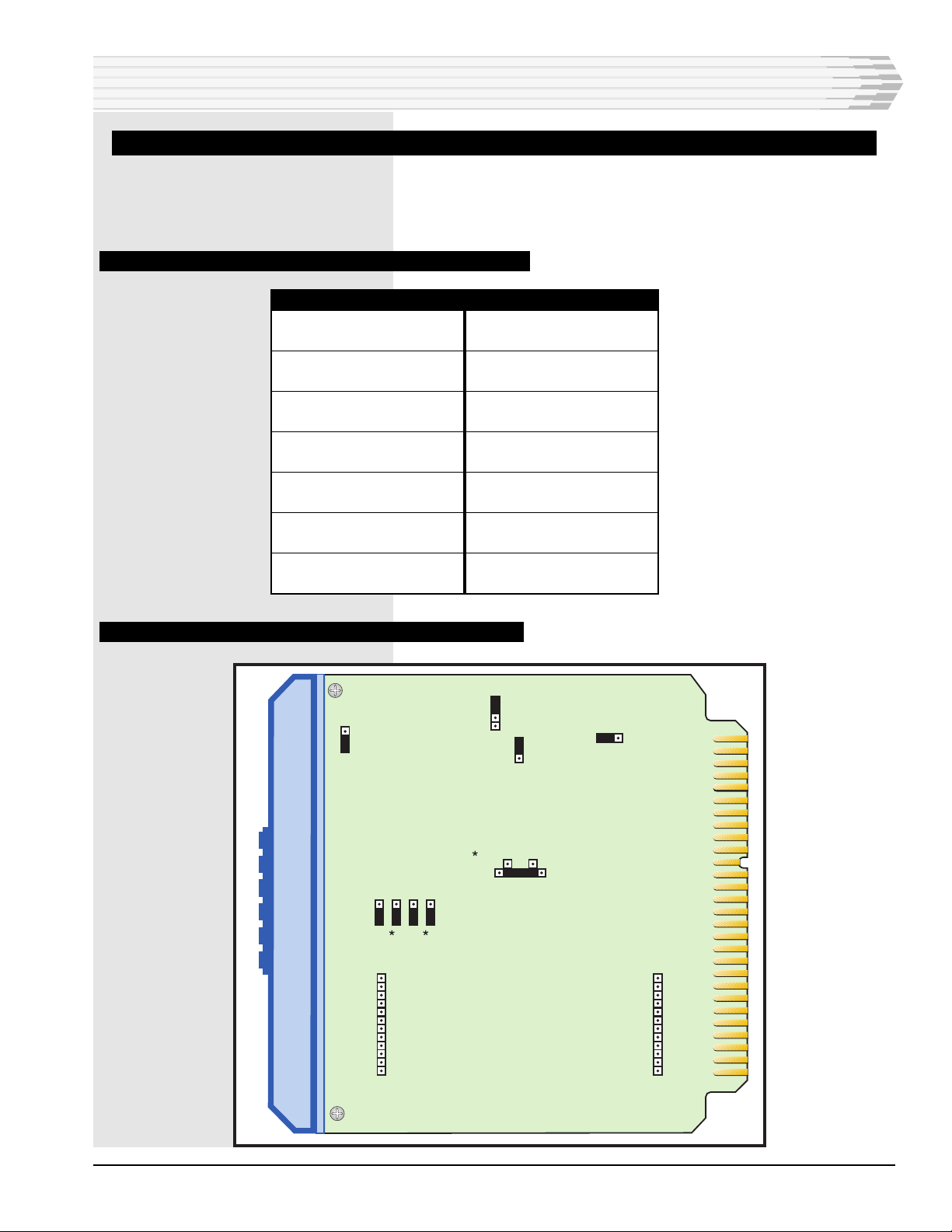
♦An A17-44020-01, comprised of the A12-49018-00 Station
Selector combined with the A11-44020-00 DTMF decoder in
slot 1 (J1).
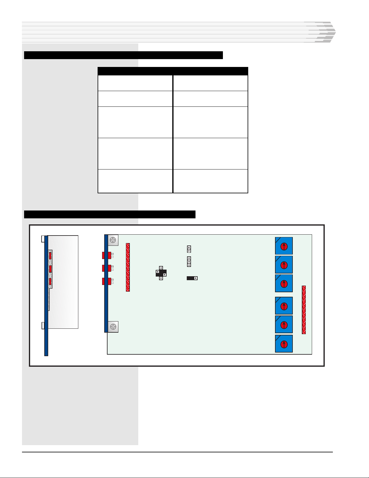
♦An A17-44931-01, comprised of the A11-44931-00 timer com-
bined with the B12-49031-00 sub assembly timer in slot 2
(J2).
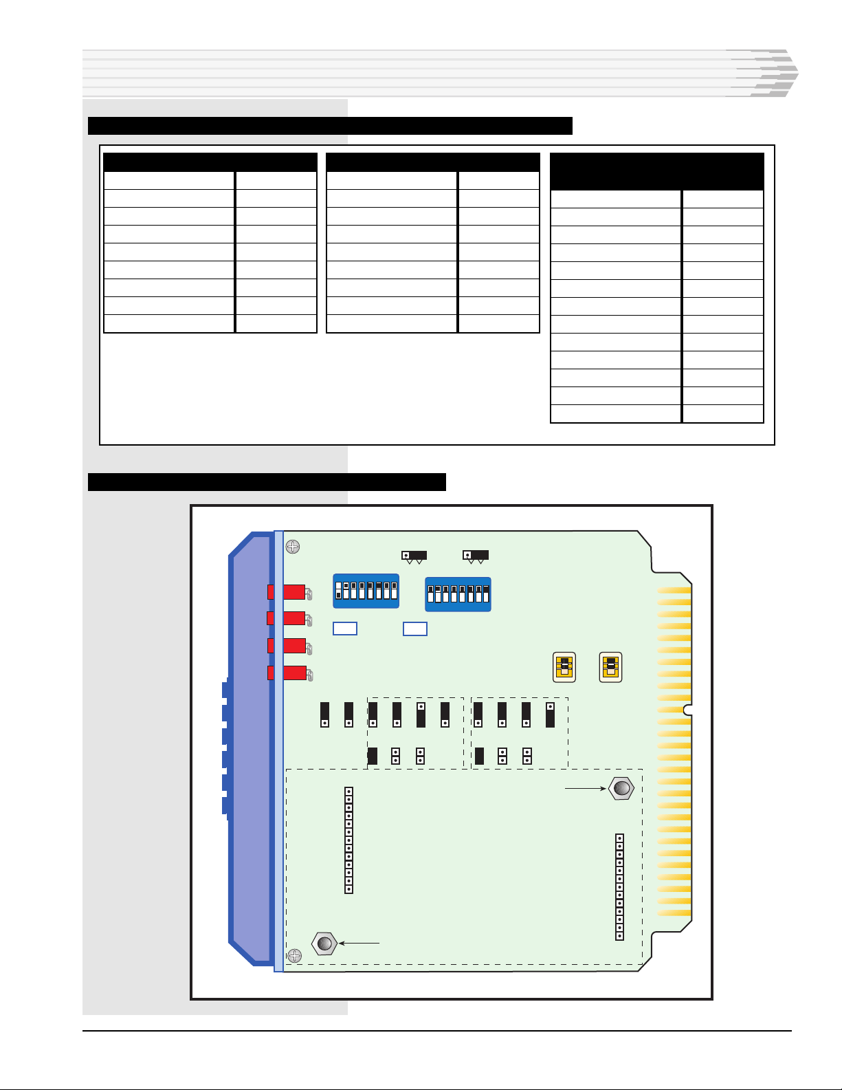
♦The A17-44118-00 4W/4W VF bridge in slot 3 (J3).
With this application, there is no signal tone sent to the PBX
telling the user that he has access to the OW system after he
has dialed the access number for the OW interface. The user will
shout down for the desired station required.

05774-0598 <90-00122> PAGE 3
INSTALLATION
This section consists of:
1. Equipment mounting
2. Wiring
3. Switch and strap settings
♦44020 DTMF Decoder
♦49018 Station Selector subassembly
♦44931 Relay Timer
♦49031 Relay Timer subassembly
♦44118 Bridge
4. Alignment procedure
EQUIPMENT MOUNTING
Install the shelf in an equipment rack using the hardware
provided. Refer to Fig. 1.
FIG. 1 - MOUNTING DIMENSIONS
8.5
4.75
1.72
17.35
19.00 or 23.00

PAGE 4 05774-0598 <90-00122>
WIRING
Wire the shelf as required. Refer to Fig. 2 for a functional
schematic of the unit.
FIG. 2 - FUNCTIONAL SCHEMATIC, 05774 SHELF
INSTALLATION
NOTE: Connect -Battery to B-1. Connect ground to B-2.
1 2 3 4 5 6 7 8 9 10
BC1
J1
J2
J3
C2
Rear View

05774-0598 <90-00122> PAGE 5
SWITCH AND STRAP SETTINGS
Refer to Tables A through D and Figs. 3 through 7 to set the
straps and switches on the modules.
TABLE A - SWITCH AND STRAP SETTINGS, 44020 DTMF DECODER
OPTION
Input Impedance
Bridging
Input Level
0 to -20 dBm
Dial Tone Filter
In
Dialing
12-digit
Auxiliary Output
* and #
* or A
Nonlatching
# or C
Nonlatching
SETTINGS
BRDG
0
DTF IN
12 DGT
#2, *2, #1, *1
PLS
PLS
FIG. 3 - SWITCH AND STRAP LOCATIONS, 44020 DTMF DECODER
INSTALLATION
1
12
J1
1
12
J2
C2
#2
A2
2
C1
#1
A1
1
16
DGT
12
0DB +10DB
-10DB
IN DTF
OUT BRDG
600 OHM
OR A # OR CCLR
EXT
CLR PLS EXT
CLR

PAGE 6 05774-0598 <90-00122>
TABLE B - SWITCH AND STRAP SETTINGS, 49018 STATION SELECTOR SUBASSEMBLY
OPTION
Reset
3 second reset
Number of Digits
3-digit Codes
Address Code 1
First Digit
Second Digit
Third Digit
Address Code 2
First Digit
Second Digit
Third Digit
Busy
SET
CLEAR
SETTINGS
IN
Digit 3
S1 = 1 (or as required)
S2 = 2 (or as required)
S3 = 3 (or as required)
S4 = 0 (any unused code)
S5 = 0 (any unused code)
S6 = 0 (any unused code)
SET A
CLR C
FIG. 4 - STRAP LOCATIONS, 49018 STATION SELECTOR SUBASSEMBLY
INSTALLATION
*
A
C
*
CKT 2
X2
X1
X6
12
P1
P2
1
12
S1
S2
S3
S4
S5
S6
IN
OUT
1 DIGIT
2 DIGIT
3 DIGIT
RESET
CLR (X5)
#
SET(X4)
1
CKT 1
0/1
49018-00
STATION
SELECTOR
CKT 1
CKT 2
0/1
#

05774-0598 <90-00122> PAGE 7
TABLE C - SWITCH AND STRAP SETTINGS, 44931 RELAY TIMER AND 49031 SUBASSEMBLY
FIG. 5 - SWITCH AND STRAP LOCATIONS, 44931 RELAY TIMER
TIMER A
RO/NO
RTI/RTO
TC/IC
NI/RI
IG/IB
C1, C2, C3
GO/BO (S1)
DIP Switches (S2)
Relay A
RO
RTI
TC
RI
IG
C1
GO
0111 1111
48V
TIMER B
RO/NO
RTI/RTO
TC/IC
NI/RI
IG/IB
C1, C2, C3
GO/BO (S3)
DIP Switches (S4)
Relay B
RO
RTI
TC
NI
IB
C1
GO
1111 1111
48V
TIMER C
(SUBASSEMBLY
RO/NO
RTI/RTO
TC/IC
NI/RI
IG/IB
C1, C2, C3
GO/BO (S1)
DIP Switches (S2)
Relay
DC-HI/AC/DC-LO
C8 IN/OUT
K1-2 IN/OUT
K1-5 IN/OUT
NO
RTO
IC
RI
IG
C1
GO
0111 1111
48V
AC
OUT
IN
IN
S2 S4
S1 S3 GO
BO
GO
BO
12
1J1
12
1J2
RO
NO
RO
NO
RTI
RT0
TC
IC
NI
RI
IG
IB
RTI
RTO
TC
IC
NI
RI
IG
IB
C1 C2 C3 C1 C2 C3
-24V -48V
RELAY A RELAY B
-24V -48V RESISTORS OUT
RESISTORS IN
R52
R20
MOUNTING STAND-OFF
MOUNTING STAND-OFF
SUBASSEMBLY
MOUNTING
AREA
TIMER
A B TIMER A TIMER B
12345678
OPEN OPEN
12345678
INSTALLATION

PAGE 8 05774-0598 <90-00122>
FIG. 6 - SWITCH AND STRAP LOCATIONS, 49031 RELAY TIMER SUBASSEMBLY
TABLE D - STRAP SETTINGS, 44118 BRIDGE
OPTION
GAIN STRAPS
Receive Port 1
0 to +7 dB
Receive Port 2
0 to +7 dB
Receive Port 3
0 to +7 dB
Receive Port 4
0 to -16 dB
Transmit Port 1
0 to -16 dB
Transmit Port 2
0 to -16 dB
Transmit Port 3
0 to -16 dB
Transmit Port 4
0 to +7 dB
FOUR-WAY BRIDGE
Summing Bus IN
Transmit Distribution Networks OUT
Receive Distribution Networks OUT
STRAP IN
1R LO
2R LO
3R LO
4R HI
1X LO
2X LO
3X LO
4X HI
B1X, B2X, B3X, B4X
D1H, D2H, D3H, D4H
H1R, H2R, H3R, H4R
INSTALLATION
12
P1
1
18
S2 REGISTER
OUT
REGISTER
IN
R32
OPEN
12
P2
1
DC HI DC LOW
OPTICAL COUPLER
24V 48V
RELAY
OUT
IN
OUT
IN
K1 2
K1 5
GO
BO
S1
C3 C2 C1
NI RI IG IB
NO RO
TC IC
RTO RTI
AC
MOUNTING HOLEMOUNTING HOLE
MOUNTING HOLE
SUBASSEMBLY
FRONT PANEL
49031-00
RELAY
TIMER
TIMER C
RELAY C
OC

05774-0598 <90-00122> PAGE 9
FIG. 7 - STRAP LOCATIONS, 44118 BRIDGE
INSTALLATION
ALIGNMENT
All straps and levels are factory-set. If necessary, refer to Fig. 8
and the section below to align the 44118 Bridge.
Equipment Required
♦Signal Generator sending a 1kHz, 600 ohm signal at various
levels.
♦600-ohm Level Meter (with and without 600-ohm termina-
tion).
1. Verify that the straps are set per Table D. Remove power from the
shelf. Insert 44118 module into slot 3. Reapply power.
2. Connect a 600-ohm terminated dB meter across the 600-ohm out-
put from the signal generator. Set the generator frequency to 1kHz.
Adjust generator level for a reading equal to system line receive
test tone level of +7dBm.
CONTINUED . . .
HI LO
1R
HI LO
3R
HI LO
2X
+ +
+
+
+
+
HI LO
2R
LO HI
HI LO
4X
+
+
+
+
+
+
H1R
D1R
D3X
H3R D3R
H2R
D2R
H4R D4R
G3X B3X
D3H
HI
LO
1X
+
++
+
+
+
+
B2X D2H
D2X
G2X
G1X
B1X D1H
D1X
D4X
D4H
B4X
G4X
HI LO
4R
3X

PAGE 10 05774-0598 <90-00122>
FIG. 8 - FRONT PANEL, 44118
3. Connect the 600-ohm terminated dB meter to the COMBINED
DIST OUTPUT jack (J9) on the 44118 front panel. The meter will
remain here for steps 4 through 7.
4. Connect the signal generator to the LINE RCV PORT 1 jack (J1) on
the 44118 front panel. Adjust LINE RCV PORT 1 level control (R7)
for a reading of -10dBm. (This is the distribution level.)
5. Move the generator to the LINE RCV PORT 2 jack (J3). Adjust
LINE RCV PORT 2 level control (R24) for a reading of -10dBm.
6. Move the generator to the LINE RCV PORT 3 jack (J5). Adjust
LINE RCV PORT 3 level control (R38) for a reading of -10dBm.
7. Remove the generator from port 3 and readjust the output from
+7dBm to -6dBm. Move the generator to the LINE RCV PORT 4
jack (J7). Adjust LINE RCV PORT 4 level control (R54) for a read-
ing of -10dBm.
8. For steps 9 through 11, leave the generator connected to J7. Do not
change the generator level or any of the receive level controls.
9. Move the 600-ohm terminated dB meter to the LINE XMT PORT 1
jack (J2). Adjust the LINE XMT PORT 1 level control (R16) for a
reading of -16dBm.
10. Move the 600-ohm terminated dB meter to the LINE XMT PORT 2
jack (J4). Adjust the LINE XMT PORT 2 level control (R31) for a
reading of -16dBm.
11. Move the 600-ohm terminated dB meter to the LINE XMT PORT 3
jack (J6). Adjust the LINE XMT PORT 3 level control (R46) for a
reading of -16dBm.
12. Remove the generator from port 4 and readjust the output from -
6dBm to +7dBm. Move the generator to the LINE RCV PORT 1
jack (J1). Do not readjust any receive level controls. Move the 600-
ohm termianted dB meter to the COMBINED DIST OUTPUT jack
(J9). Verify a reading of -10dBm.
13. Move the 600-ohm terminated meter to the LINE XMT PORT 4
jack (J8). Adjust the LINE XMT PORT 4 level control (R62) for a
level of 0dBm.
14. Calibration of the 44118 is complete. Remove the signal generator
and the dB meter.
INSTALLATION
A11-44118-
44118-00
DISTRIBUTION
BRIDGE
LINE RCV
PORT 1
PORT 2
PORT 3
PORT 4
COMBINED
DIST
OUTPUT
PORT 1
PORT 2
PORT 3
PORT 4
LINE XMT
44118-00 REV__
J1
J3
J5
J7
J9
J2
J4
J6J6
J8
R7
R24
R38
R54
R16
R31
R46
R62

05774-0598 <90-00122> PAGE 11
OPERATION
Refer to Fig 2. In the idle condition, relays KA, KB and KC
are released and timers TA, TB and TC are not active. The
relays and the timers are located in slot J2. Relay KB, being
released, cut and terminate the input to the VF bridge (J3) and
it will also cut and terminate the PBX output pair. (B-5 and B-
6). This will prevent the placing of any VF coming from the PBX
on the ORDER WIRE side of the system. The PBX is connected
to port 4 of the bridge. The port 4 TX output of the bridge will go
to the input of the 44020/49018 DTMF decoder and to the input
of the PBX. (B-3 and B-4)
SEIZURE OF THE INTERFACE.
Seizure from the Order Wire
The 44020/49018 decoder will reset itself every 3 seconds, after
each digit is detected.
Assume the decoder is set for address 1, 2, 3, “*” for the VNET
access code. When the user dials the 3 digit code 1, 2 , 3 the
output of the decoder detecting the correct code will operate
relay KA for 3 seconds. When the user dials the “*” after 1, 2, 3
has been detected and relay KA has operated, a ground from the
detected “*” will appear on pin 12 of the 49018 assembly.
This ground will create a latch on the 49018 that will place a
ground on pin 7 of the 49018. This latched ground is placed on
relay KB and timer TA. Timer TA is used to seize the PBX and it
can be strapped to have battery or ground as an output depend-
ing on the user’s requirement. Relay KB will operate and re-
move the shunt on the input pair from the PBX and dial tone
will be heard by the order wire user when the PBX is seized.
The PBX seizing, will place battery or ground on its M lead
which will go to timer TB. TB can be strapped for either battery
or ground as an input. TB turning on will place an additional
holding ground on timer TA and relay KB. This ground will also
operate timer TC which is a 1/2 second 1 shot timer . When TC
turns on, it will reset the 49018 latch. The ground that was
coming out of the 49018 latch, on pin. 7, will be removed. The
holding path for KB and TA is order wire timer TB which is
being held by the E lead being active. (M lead of the PBX turned
on)
The diode between TA and TB assures that the TC timer can
only be activated by timer TB turning on. The interface is now
under control of the M lead from the PBX. TC cannot retrigger
until after the ground on its input has been removed and is
reapplied.
Seizure from the PBX
When the PBX number for the interface is dialed, the M lead
from the PBX will place a battery or ground on TB of the inter-
face depending on the user’s requirement. TB will be optioned so
NOTE:
The 05774 Interface M Lead
(pin 34) connects to the PBX
E Lead.
The 05774 Interface E Lead
(pin 9) connects to the PBX
M Lead.

PAGE 12 05774-0598 <90-00122>
OPERATION
that it is a slow to operate relay. (50 msec) After the slow to
operate period, TB will output a ground which will turn on relay
KB. This will remove the VF shunt and it will also turn on timer
TA which will place either a ground or battery on the E lead of
the PBX. The PBX will now be seized and the release of the
interface will be as described below.
RELEASE OF THE INTERFACE.
From the Order Wire
The user will dial the 3 digit code (1, 2, 3 for this example) plus
“#” and relay KA will turn on for 3 seconds when the 3 digits are
detected. When the “#” is dialed, the decoder will output a
ground on pin 27 through the operated KA contacts. Relay KC
will turn on and lock to the ground from the output of timer TB
which is being held by the E lead input on its input. (M lead
from the PBX)
Relay KC turning on will open the M lead from TA to the PBX E
lead. The PBX will have its E lead removed and relay KC will
not be able to release until the PBX removes its M lead to the E
lead of the VNET interface which will restore TB. When the
PBX removes its M lead (E lead on the VNET interface) TB will
release and the ground to KB and KC will be removed releasing
them.
KB releasing will replace its terminations on the VF bridge and
the PBX. KC releasing will reclose the TA output path to the
PBX E lead. TA is inactive and the PBX will not reseize. KA will
release after 3 seconds when the decoder resets itself. The ‘#”
detection is only on for as long as the tone is present. The
system is back to normal.
From the PBX side
The user of the PBX will hang up his phone and the PBX M lead
(E lead on the interface) will be restored. This will cause TB to
release and TB releasing will release TA and KB. The E lead
from the interface to the PBX M lead will be restored and the
PBX will be dropped.
KB releasing will replace the terminations on the VF bridge so
the order wire users will not hear any VF from the PBX.

05774-0598 <90-00122> PAGE 13
TECHNICAL SPECIFICATIONS
DESCRIPTION
Input Voltage Range
Input Power Requirement @ -48VDC *
Idle
Full Load
Heat Dissipation @ -48VDC
Idle
Full Load
Physical Dimensions
19"
23"
Weight
Operating Temperature Range
VALUE
-21 to -56 VDC
110 mA
271 mA
24.73 Btu/Hr
44.72 Btu/Hr
19" x 8.25" x 1.72"
23" x 8.25" x 1.72"
6.75 lbs
0° to 60° C.
NOTE: There is no appreciable difference between the power requirements at
-24 VDC and those at -48 VDC.

PAGE 14
14 PAGES 05774-0598 <90-00122>
LIMITED WARRANTY
The Seller warrants that the standard hardware products sold will be free from defects in material and work-
manship and perform to the Seller’s applicable published specifications for a period of 18 months for hardware,
and 3 months for software, from the date of the original invoice. The liability of the Seller hereunder shall be
limited to replacing or repairing, at its option, any defective products which are returned F.O.B. to the Seller’s
plant, (or, at the Seller’s option, refunding the purchase price of such products). In no case are products to be
returned without first obtaining permission and a customer return authorization number from the Seller. In
no event shall the Seller be liable for any consequential or incidental damages.
Equipment or parts which have been subject to abuse, misuse, accident, alteration, neglect, unauthorized
repair or installation are not covered by warranty. The Seller shall make the final determination as to the
existence and cause of any alleged defect. No warranty is made with respect to custom equipment or products
produced to the Buyer’s specifications except as specifically stated in writing by the Seller in the contract for
such custom equipment.
This warranty is the only warranty made by the Seller with respect to the goods delivered hereunder, and may
be modified or amended only by a written instrument signed by a duly authorized officer of the Seller and
accepted by the Buyer.
Warranty and remedies on products not manufactured by the Seller are in accordance with warranty of the
respective manufacturer. THE SELLER MAKES NO OTHER WARRANTY OF ANY KIND WHATSOEVER,
EXPRESSED OR IMPLIED; AND ALL IMPLIED WARRANTY OF FITNESS FOR A PARTICULAR PUR-
POSE WHICH EXCEEDS THE AFORESAID OBLIGATIONS IS HEREBY DISCLAIMED BY THE SELLER.
INCASE OF DIFFICULTY
If you experience difficulty with this equipment, check the following, as appropriate:
1. Switch settings
2. Signal levels
3. Software configuration
4. Connections between Dantel’s equipment and your equipment.
If there is still a problem, substitute equipment that is known to be good. For additional assistance, call
Dantel’s Technical Field Service Department weekdays, 6 A.M. to 5 P.M. pacific time:
1-800-4DANTEL(1-800-432-6835).
If a thorough checkout shows a piece of equipment has malfunctioned, you may return it to the factory. For
repairs and emergency replacements, obtain a Return Material Authorization (RMA) number from the Cus-
tomer Service Representative at 1-800-4DANTEL (1-800-432-6835).
To ensure expedient processing of your order, provide a purchase order number and shipping and billing
information when requesting an RMA number. Also, when the units are returned to Dantel, include a descrip-
tion of the failure symptoms for each unit returned. Send defective equipment to:
Dantel, Inc. • 2991 North Argyle Avenue • Fresno, California 93727-1388
P.O. Box 55013 • Fresno, CA 93747-5013 Phone (209) 292-1111 Fax (209) 292-9355 http://www.dantel.com
WARRANTY
This manual suits for next models
2
Table of contents
Other Dantel Recording Equipment manuals