Dantel 44023 User manual

CAUTION
Install or remove modules from the shelf only when the power is off.
If you install a module in the shelf with the power on, the internal
circuitry may suffer damage and the product warranty will be void.
Remove and install circuit boards only in a static-safe environment
(use antistatic wrist straps, smocks, footwear, etc.).
Keep circuit boards in their antistatic bags when they are not in use.
Do not ship or store circuit boards near strong electrostatic, electromag-
netic, magnetic, or radioactive fields.
For more complete information on electrostatic discharge safety
precautions, refer to BellcoreTM Technical Reference #TR-NWT-000870.
Copyright 1997 by Dantel, Inc. • Dantel is a registered trademark of Dantel, Inc. • ISO 9001 Registered
Printed in the U.S.A.
INSTALLATION&OPERATION MANUAL
44023-1297<90-00058>
44023
PABX/TRUNK
INTERFACE MODULE
About this Practice:
• This document has been
reformated to meet ISO 9001
requirements.
Issue date: December 1997
Reissued Practices: Updated and
new content can be identified by a
banner in the right margin.
UPDATED
Table of Contents
Ordering Information ........................................................................... 2
General Description.............................................................................. 2
Circuit Description ............................................................................... 3
Application Information ..................................................................... 10
Installation.......................................................................................... 13
Operation ............................................................................................ 20
Technical Specifications ..................................................................... 21
Warranty ............................................................................................. 22

PAGE 2 44023-1297<90-00058>
ORDERING INFORMATION
NOTE: This section lists the different options available for this product. To order any of the avail-
able options, contact Dantel Inside Sales through our toll-free number, 1-800-432-6835.
OPTION NUMBER FEATURES
A11-44023-00 PABX/Trunk Interface Module
GENERAL DESCRIPTION
The 44023 PABX/Trunk Interface Module (44023) pro-
vides:
♦A four-wire trunk interface for a 440 Communications Man-
agement System (440 CMS).
♦An two-wire line interface for a 44443 Four-Wire Termina-
tion Set.
The 44023 is a plug-in printed circuit module that fits into any
400-type or similar equipment housing. The 44023 does not
accept subassemblies.
Strap options lets you:
♦Select level range
♦Configure E and M leads
♦Select ground or loop start
♦Select privacy and busy mode
♦Select the conference delay feature
The 44023 functions in a 440 CMS trunk interface circuit with
the following modules:
♦44020 DTMF Decoder Module
♦44021/49021 Address Decoder Module
♦49020 Tone Supply Subassembly
The 44023 converts any subscriber station to a trunk interface
by directly replacing a 44022 Subscriber Line Interface Module
in the 440 CMS Multi-Station Package. Convert the trunk
interface to two-wire by installing a 44443 Four-Wire Termina-
tion Set to the right of the 44023.
The front panel includes:
♦Operational status indicating LEDs
♦Calibration test points
♦Monitor jacks
♦A test/reset switch
The 44023 operates on -21 to -56 VDC input power.

44023-1297<90-00058> PAGE 3
CIRCUIT DESCRIPTION
The PABX/Trunk Interface Module circuitry consists of three
sections: audio, signaling/control and power regulator.
AUDIO SECTION
The audio section consists of a receive circuit and a transmit
circuit. Refer to Fig. 1.
Here is a brief description of each of the functional parts of the
circuit:
Receive Circuit
The receive circuit consists of:
♦A line input (receive) transformer (T1)
♦Input pad
♦Summing circuit
♦Mute FET
♦Busy and alert tone FETs
♦Level Control (R5)
♦Amplifier
♦Drop output (receive) transformer (T2)
♦Drop receive/monitor jacks
LINE RCV signals (pins 2 and 4) feed through T1 to the pad.
This pad provides 23 dB of attenuation which prevents
overdriving the mute FET. You can strap the attenuation out in
cases of low line levels (below -5 dBm). Use the summing inputs
in the 440 CMS multi-station package.
External 49020 Tone Supply Subassembly busy and alert tones
connect to pins 36 and 32 respectively. The circuits signaling/
control section operates control FETs for these tones and the
mute. Set the amplifier gain with R5. The drop output feeds
through T2 and the jacks to pins 13 and 7.
Transmit Circuit
The transmit circuit consists of:
♦Drop transmit/monitor jacks
♦A drop input (transmit) transformer (T4)
♦Transmit pad
♦Mute FET
♦Off-hook and on-hook tone FETs
♦Level control (R24)
CONTINUED . . .

PAGE 4 44023-1297<90-00058>
FIG. 1 - FUNCTIONAL SCHEMATIC, 44023 PABX/TRUNK INTERFACE MODULE, AUDIO SECTION
CIRCUIT DESCRIPTION
2T1
4
LINE RCV
-8VDC
OUT
IN
T2 TEST
JACKS
DROP/
MON 7
13
DROP RCV
XMT
PAD
23dB
-8VDC
9
10
11
8
36
32
38
40
41 T3
47
42
35
17
XMT LEVEL ADJ
R24 OUT
RCV
PAD
23dB
IN
-8VDC
T4
51
53
TEST
JACKS
DROP/
MON
-8VDC
-20/-18
POWER
SUPPLY
REGULATOR
-10/-8
POWER
SUPPLY
REGULATOR
-18 VDC
TP 10
-10 VDC
-8 VDC
TP 9
PINS
MON
RCV OR
XMT
TO
MODULE
CIRCUIT
JACK
DETAIL
DROP
XMT
-8VDC
RCV LEVEL ADJ
R5
LINE
RCV
SUMMING
INPUTS
MUTE
BUSY TONE
BUSY TONE
ENABLE
ALERT TONE
OFF-HOOK
TONE ENABLE
OFF-HOOK
OK TONE
ON-HOOK
OK TONE
ON-HOOK
TONE ENABLE
GND
RCV DIST
XMT DIST
DISTRIBUTION
OUT
LINE XMT
LINE XMT
-20 VDC
-8VDC
-BATT
(-21 TO -56 VDC)

44023-1297<90-00058> PAGE 5
♦Amplifier
♦Distribution circuit
♦Line output (transmit) transformer (T3)
DROP XMT signals (pins 53 and 51) feed through T4 to the pad.
This pad provides 23 dB of attenuation which prevents
overdriving the mute FET. You can strap the attenuation out in
cases of low line levels (below -5 dBm).
49020 Tone Supply Subassembly off-hook and on-hook tones
connect to pins 38 and 40 respectively. The circuits signaling/
control section operates control FETs for these tones and the
mute. Set the amplifier gain with R4. The output signal splits
between the distribution circuit and the LINE XMT output.
The distribution circuit feeds the 440 CMS Multi-Station Pack-
age at pin 42. The line output feeds through T3 to pins 41 and
47.
SIGNALING/CONTROL SECTION
The signaling/control section processes incoming calls and
outgoing calls. Refer to Fig. 2.
Incoming Calls
The 44023 processes incoming call signaling in one of two ways:
with a two-wire outside facility or a four-wire E and M trunk.
When an incoming call initiates from a two-wire outside facility,
the ring signal (66 Hz to 16 Hz) applies to the 44023 through
two-wire tip and ring leads (pins 44 and 50) to the OC2 detector.
A loop control strap option determines whether the calling
party or only the called party can terminate the call. A wink or
ground removal on the tip terminates a call. Relay K1 closes the
A-B lead contacts (pins 48 and 54) when the 44023 answers the
call.
When an incoming call initiates from an E and M trunk, the
E Lead ring signal applies to pin 1. A E control strap option
determines whether the calling party or only the called party
can terminate the call. The M lead output (pin 21) switches
when the 44023 answers the call.
The OC2 outputs and the E lead circuit apply through a control
timer to:
♦A 10 to 80-second no answer disconnect timer.
♦Through the line seize logic to relay K1, control transistor
Q12, and M lead relay K2.
CONTINUED . . .
CIRCUIT DESCRIPTION

PAGE 6 44023-1297<90-00058>
FIG. 2 - FUNCTIONAL SCHEMATIC, 44023 PABX/TRUNK INTERFACE MODULE, SIGNALING/CONTROL SECTION
CIRCUIT DESCRIPTION
-DC
20
INPUT
OUTPUT
CONTROL
LOGIC
SECTION
22 DELAY ON
AND OFF
CONFERENCE
IN OUT
PRIVACY
OUT IN
BUSY
CONTROL
STRAP OPT.
E-LEAD
CONTROL
STRAP OPT.
24
26
Q5
-BATT
-DC K3
29
K3
46
GND START IN
OUT
44
48 K1 A B
-10VDC
54
50
56 OUT
IN
LOOP
START
200Ω
OC 2
OC 1
52
1
18
14
39
TEST RESET
CC1
MANUAL CLR
PWR-UP CLR
E LEAD
OUT
IN
A
C
B
IN
OUT
ECHO SUPPR
CALL GROUP
STATION CALL
BUSY CONTROL
BUSY
* Regroup "To Analog Section"
*BUSY TONE
ENABLE
*MUTE
*OFF HOOK
TONE ENABLE
OFF HOOK
-DC
INC CALL
-DC
Q11
19
*ON HOOK
TONE ENABLE
CCO
-DC
Q12
Q13
K1
K2
6M N C
M BATT
OUT IN
21 M LEAD
M N O
OUT IN
M GND
M LEAD
33
K2
"M"
CLR
2W T
2W R
DELAY ON
20 MS
DELAY TIMER
1 SEC. ON
1 SEC. OFF
60 SEC. FADE
DELAY TIMER
Q9
-DC

44023-1297<90-00058> PAGE 7
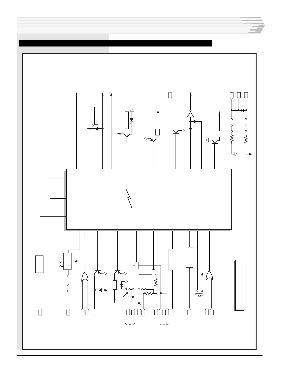
The radio controls are switched on with Q9 (open collector). A
one-second delay network delays the radio control switch off.
The control timer provides a transmission delay of the drop and
line off-hook tones when you include radios or satellites in the
440 CMS. This delay turns on radios before you transmit the
tones.
The control timer provides two delay periods. The first delay
period (100 milliseconds) occurs at the end of a one-half second
charge period. The output of the inverter switches to a logic zero
(-10 VDC). Transistor Q12 switches on and starts the drop and
line off-hook tone burst timer (100 milliseconds) charge periods.
The on-hook tone burst timer also charges.
When Q12 switches on, relay K1 energizes. Contacts K1A close,
which:
♦Connects a 200 ohm load across the two-wire tip and ring
inputs (through the A and B leads of a term set).
♦Answers the call.
♦Terminates the ring signal input to OC2.
When the ringing stops, the control timer tank circuit starts a
200 millisecond discharge delay period. At the end of the delay
period, the output of the control timer inverter switches to a
logic one (0 VDC). This causes the off-hook tone burst timers to
discharge, closing off-hook and alert-tone FETs and applying a
burst of tone to the LINE XMT and DROP RCV, respectively.
The off-hook LED also comes on.
The duration of the alert tone burst (proceed-to-dial signal) to
the drop is 0.12 seconds. This is to ensure that the system is
normalized before additional DTMF tones (address codes) are
sent. When the alert tone burst ceases, it indicates that the two-
or three-digit code for the desired 440 system station can be
dialed. The duration of the off-hook tone burst to the line is also
0.12 seconds. This is used to busy out the 440 system.
The no answer disconnect timer is also started when Q12 and
Q13 are turned on. If the incoming call is not answered within
the set time (10 to 80 seconds) the call is automatically discon-
nected. The timer activates an on-hook tone burst through the
line seize logic to unbusy the 440 system.
When the incoming call is answered at the 440 system remote
site, a ground is applied to the busy input (pin 22) from the
44021 Address Decoder in response to the off-hook tone. This
off-hook tone is generated at the remote site by a 49020 Tone
Supply Subassembly, activated through the remote 44022
Station Interface Module and applied to the 44021. The 44023
control circuit input (CCI) lead (pin 18) is grounded, either
permanently or through a switch.
The receipt of the busy input and CCI lead ground puts the
44023 under the control of the 440 system site and disables the
no answer disconnect timer. This allows the call to proceed
indefinitely or until the 440 system site goes on hook.
CIRCUIT DESCRIPTION

PAGE 8 44023-1297<90-00058>
When the 440 system site phone goes on hook, an on-hook tone
is decoded by the 44021. This causes the ground at pin 22 to be
removed, releasing the 44023 line seize logic to unbusy the 440
system. The 440 system is not busied by placing the outside
facility telephone on hook, unless the 44023 is strapped for
outside party control (Loop Control in)
The CCI circuit includes a 60-second fade delay timer. This
timer prevents a call from being disconnected should the radio
signal strength fade or a momentary interruption occur. The
44023 will disconnect from the outside call after one second if
the E lead ground is removed.
If an incoming ring signal is applied to the 44023 when the 440
system is internally busy, the 44023 will answer the incoming
call with a seven-second busy tone timer. The circuit will then
automatically disconnect the incoming call. The 44023 INC
CALL LED will come on for the duration of the seven-second
busy tone.
The transmit and receive mute FETs are unmuted when Q9 and
Q12 are switched on. This allows communications to proceed
when the 440 system phone is answered.
Outgoing Calls
An outgoing call from a system facility is initiated when a 440
system station telephone is lifted off hook. This transmits an
off-hook tone which causes the 44021 Address Decoder to ground
pin 22. The CCI (pin 18) must also be ground.
When the 440 system station telephone is taken off hook, the
440 system is busied out and the 44023 CKT BUSY LED
comes on. The calling party then dials the appropriate two- or
three-digit code to access the 44023 for the desired outside line.
When the last digit is dialed, the 44021 Address Decoder
grounds station call (pin 24) or group call (pin 26). The selected
call input (pin 24 or 26) is applied through a 400ms line seize
delay circuit. This delay prevents the last digit of the code dialed
from being tranmitted over the outside facility as the first digit
of an outgoing number.
When the call input is processed through the line seize logic Q12
turns on. This closes relay K1 and seizes the line. A ground
start strap option allows a momentary ground to be applied to
the tip (pins 44 and 46) to originate a call. Relay K2 switches the
M lead. The OFF HK LED comes on, the CKT BUSY LED goes
off, and the calling party receives a dial tone from the outside
facility. The calling party can now dial any desired outside
number.
When the outside call is terminated, a 0.2 second on-hook tone
burst from the 440 system is decoded by the 44021 Address
Decoder. This removes the ground from pin 22, which releases
the line seize logic and unbusies the 440 system.
CIRCUIT DESCRIPTION

44023-1297<90-00058> PAGE 9
For both incoming and outgoing calls, release of the CCO lead
through Q9 is delayed one second by a delay to release timer.
This makes sure the on-hook tone is transmitted before the CCO
lead releases the radio transmitter.
Clear Circuit
The clear function occurs when:
♦The phone hangs up.
♦90 seconds elapse during off-hook.
♦The call terminates before the phone answers.
When the phone hangs up, a pulse at the reset output (pin 3)
resets the 44020 DTMF Decoder Module and returns the circuit
to its normal condition.
Terminate a call before the phone answers by applying a ground
to the clear input (pin 16). Application of ground returns all
functions to normal and outputs a reset pulse at pin 3. The tone
decoder normally applies the clear input upon receipt of an
on-hook tone.
You can use the front panel TEST/RST switch for card align-
ment. Pressing the button once causes an off-hook condition.
Pressing the button again resets the 44022 SLIM.
POWER REGULATOR SECTION
The power regulator consists of two voltage regulators. One
provides -20 VDC to the 44023 circuitry and -22 VDC to the next
regulator. The second regulator provides -10 VDC and -8 VDC to
the 44023 circuitry. Input power can range from -21 VDC to
-56 VDC.
CIRCUIT DESCRIPTION

PAGE 10 44023-1297<90-00058>
APPLICATION INFORMATION
The 44023s primary application is to interface a four-wire
trunk or two-wire outside line to Dantels 440 Communica-
tion Management System. The module also interfaces control
functions between the outside facilities and the 440 system.
The 44023 can be used in custom package applications of the
440 System. Modules necessary to provide the signaling and
control interface for the 44023 include:
♦44020 DTMF Decoder
♦49020 Tone Supply Subassembly
♦49018 Address Decoder (or 44021/49021 Address Decoder
with subassemblies)
Fig. 3 shows an E and M trunk application diagram. Fig. 4
shows a two-wire line application diagram.
440 System Functions
For an outgoing call, the 44023:
♦Seizes the trunk or line when a station or group call input is
applied from a decoder,
♦Sends an off-hook tone to the caller,
♦Passes dial tone from the trunk to the caller, and
♦Passes signaling tones from the caller to the trunk.
The call is terminated when the station call or group call input
is removed by the decoding of an on-hook tone from the caller.
For an incoming call from the trunk or line, the 44023 answers
the ring by seizing the line. It sends an:
♦Off-hook tone to the 440 system, and
♦An alert tone to the trunk.
If the 44023 does not receive an off-hook tone from the 440
system within 10 to 80 seconds (adjustable), it will terminate the
call (Loop Control in). If the 440 system is busy when the incom-
ing call is placed, the 44023 will:
♦Answer the call,
♦Provide a seven second busy tone to the caller, and
♦Terminate the call.

44023-1297<90-00058> PAGE 11
FIG. 3 - E AND M TRUNK APPLICATION DIAGRAM
APPLICATION INFORMATION
T
CD
RCV
CCI
17
-21/-56VDC
*
-21/-56 VDC
35
{
35
R
T
R
2
4
41
47
7
13
51
53
T
R
T
R
RCV
DROP
XMT
E LEAD
M LEAD
LINE
XMT
17
35
14
18
19
MANUAL
CLEAR
PITT
49 55
44020
DTMF DECODER
39
-21/-56 VDC
POWER-UP CLEAR
49018
STATION SELECT
12
11
10
9
8
7
6
5
4
3
2
1
BUSY
GROUP CALL
STATION CALL
39
24
26
22
E CONTROL
**
-BATT
CCO
1
6
21
33
38
40
36
32
MN.C.
MN.O.
OFF-HOOK TONE
ON-HOOK TONE
BUSY TONE
ALERT TONE
6
5
4
3
17
REGULATOR
* TO RADIO, IF APPLICABLE. IF RADIO NOT USED, GROUND PIN 18.
** STRAP E CONTROL FOR CALLER CONTROL.
49020
TONE SUPPLY
-10VDC
-20VDC
GND

PAGE 12 44023-1297<90-00058>
APPLICATION INFORMATION
FIG. 4 - TWO-WIRE LINE APPLICATION DIAGRAM
18
T
17
14
K3
17
35
-DC
** K1
44023
PABX/TRUNK
INTERFACE ECHO
SUP. 44443
TERM SET
25
29
49
55
15
5
ECHO SUPPRESSION
35
17
47
41
4
2
29
53
51
13
7
-21/-56VDC
MANUAL
CLEAR
19
CD
PTT
R
T
R
RCV
LINE
XMT
{
*OC2
GND
START
OC1
LOOP
CONT.
54
50
52
44
46
48
38
40
36
32
(USE ONLY IF NEEDED)
ALERT TONE
BUSY TONE
ON-HOOK TONE
OFF-HOOK TONE
R
47
45
43
41
B
A
T
R
T2W
DROP
6
5
4
3
44099
OR OTHER HOST
MODULE
49020
TONE SUPPLY
-10 VDC
-20 VDC
GND
REGULATOR
-21/-56 VDC
RADIO, IF APPLICABLE. IF RADIO NOT USED, GROUND PIN 18
STRAP LP CONTROL FOR CALLER CONTROL
*
**
49 55
12
11
10
9
8
7
6
5
4
3
2
1
BUSY
GROUP CALL
STATION CALL
49018
STATION SELECT
44020
DTMF DECODER
35 17 39 POWER-UP CLEAR
-21/-56 VDC
22 26 24 39

44023-1297<90-00058> PAGE 13
INSTALLATION
I
nstallation consists of setting the straps, wiring the connector,
mounting the module in the shelf and checking out the
module.
1. INSTALL THE PROPER STRAP OPTIONS.
Refer to Fig. 5 and Table A
FIG. 5 - 44023 PABX/TRUNK INTERFACE MODULE STRAP OPTION LOCATIONS.
44023-00
PABX/TRUNK
INTERFACE
BUSY
INC CALL
OFF HOOK
TRANSMIT
LINE
DROP MON
TEST RST
LINE
DROP MON
RECEIVE
DIST
DIST
GND
GND
A11-44023-00 REV__
INC CALL LED
OFF HOOK LED
XMT LEVEL
ADJUST
RCV LEVEL
ADJUST
GND
START
LP
CONT
M LEAD
BATTERY
CONF
E CONT
IN
OUT
IN
OUT
IN
OUT
OUT
IN
IN OUT
IN OUT
BUSY LED
M LEAD GROUND
IN
OUT
PRIVACY
BUSY CONTROL
IN
OUT
RCV PAD
IN OUT
XMT PAD
IN OUT
R73
R24
R5
STRAP OPTIONS
Receiving and Transmit Pads
It is recommended that the pads be strapped in unless the
calibration levels desired cannot be reached. Both pads attenu-
ate the signal by 23 dB. A mini-jumper must be installed in
either the IN or the OUT position for the module to function
properly.
CONTINUED . . .

PAGE 14 44023-1297<90-00058>
OPTION
LINE RCV LEVEL
-3 dBm to +7 dBm
-16 dBm to -3 dBm
DROP XMT LEVEL
-3 dBm to +7 dBm
-16 dBm to -3 dBm
PRIVACY
Automatic or Manual Privacy
No Privacy
M LEAD
Dry Contact
Ground Normal; -Batt. Operated
Ground Normal; Open Operated
Open Normal; -Batt. Operated
E LEAD
Interfacing E & M Trunk
Other Interfaces
LOOP START
PABX under own control (wink off)
Other
GROUND START
PABX using ground start
Other
CONFERANCE CALLING 10 SEC. DELAY
When using automatic privacy
No delay
BUSY CONTROL
Common decoder for subscriber
module and PABX module
Dedicated decoder
INSTALL STRAP
RCV PAD IN
RCV PAD OUT
XMT PAD OUT
XMT PAD IN
PVT IN
PVT OUT
M BATT OUT
M GND OUT
M BATT IN
M GND IN
M BATT OUT
M GND IN
M BATT IN
M GND OUT
E CONT IN
E CONT OUT
LP CONT IN
LP CONT OUT
GND ST IN
GND ST OUT
CONF IN
CONF OUT
B CONT IN
B CONT OUT
INSTALLATION
TABLE A - 44023 PABX/TRUNK INTERFACE MODULE STRAP OPTIONS

44023-1297<90-00058> PAGE 15
Privacy
This strap option allows the normal privacy function to be
defeated so that a caller will not receive a busy signal when the
system is in use. Incoming calls will be announced by an
off-hook tone and the caller will be connected to the system
immediately.
Busy Control
Place this strap IN when the 44023 is used in a 440 System
multi-station package.
Conference
Place this strap IN when off-net conferencing will be used.
E Lead Control
Place this strap IN when the outside trunk uses E and M
signaling, and when it is desired to allow the calling party to
have control.
Ground Start
Place this strap IN when the outside line uses ground start.
Even if the loop control strap is OUT, this strap must be IN
to allow seizing the line in a ground start situation.
M Lead
Two straps are provided for the M Lead. One is used to connect
the normally closed side of the relay to ground. The other is used
to connect the normally open side of the relay to battery. Both
straps have 4700 ohms in series (1 watt).
Normal relay position is when no call is in progress (module
on-hook). The M Lead contacts are also accessible at pins 6 (N/C)
and 33 (N/O).
Timer
The no answer disconnect timer can be adjusted with R73. Turn
clockwise to increase timer. Refer to Fig. 5.
2. WIRE THE CONNECTOR.
If you wire the connector, refer to Fig. 6 for the module connec-
tor pin wiring assignments.
INSTALLATION

PAGE 16 44023-1297<90-00058>
FIG. 6 - 44023 PABX/TRUNK INTERFACE PIN DESIGNATIONS
INSTALLATION
56 55
54 53
52 51
50 49
48 47
46 45
44 43
42 41
40 39
38 37
36 35
34 33
32 31
30 29
28 27
26 25
24 23
22 21
20 19
18 17
16 15
14 13
12 11
10 9
87
65
43
21
CIRCUIT SIDE
OF PC BOARD
COMPONENT SIDE
OF PC BOARD
C LEAD
DROP XMT, RA LEAD
DROP XMT, T2W RING, OUT
2W RING, IN
LINE XMT,RB LEAD
2W TIP, OUT
2 W TIP, IN
LINE XMT, TDISTRIBUTION OUT
POWER-UP CLEARON-HOOK TONE INPUT
OFF-HOOK TONE INPUT
- BATTERYBUSY TONE INPUT
M LEAD, NORMALLY OPEN
ALERT TONE INPUT
ECHO SUPPRESSION
GROUP CALL
STATION CALL
M LEADBUSY
CIRCUIT CONTROL OUTPUTBUSY CONTROL
GROUNDCIRCUIT CONTROL INPUT
DROP RCV, RMANUAL CLEAR
SUMMING INPUT
SUMMING INPUTSUMMING INPUT
DROP RCV, TSUMMING INPUT
M LEAD, NORMALLY CLOSED
LINE RCV, R
E LEADLINE RCV, T

44023-1297<90-00058> PAGE 17
3. MOUNT THE MODULE IN THE EQUIPMENT SHELF.
Slide the module along the guide slots then firmly seat the edge
connector in its receptacle.
4. CHECK OUT THE MODULE.
Refer to Table B for checkout procedures. Refer to Fig. 7 for a
front panel view.
Use the following test equipment for module checkout:
♦Level Meter (Weston Model 666, Hewlett-Packard 440EL or
similar equipment, or you can use a Dantel 8002 Test Set)
♦Test oscillator (Dantel 8002 Test Set or any 600 ohm audio
oscillator)
NOTE: You only need a test oscillator when you test the 44023 in an
assembly that does not have a 44011 Line Interface Module.
You can normally use the test oscillator built into the 44011
Line Interface Module.
NOTE:
The 44023 drop side always in-
terfaces to the outside world,
central office or PABX trunk. The
line side interfaces the 440 CMS
or other private network.
INSTALLATION
If you install the 44023 in a 440 CMS Multi-Station
Package, check out the 44010/11, 49020, 44020, 44021
and 49018 modules before checking out the 44023.
Test the following outputs with the appropriate equip-
ment:
♦ Monitor output
♦ Buzzer lead
♦ Lamp lead
♦ Busy-circuit light output
The system test procedure tests the all-call and group-
call functions.
FIG. 7 - 44023 PABX/TRUNK INTERFACE FRONT PANEL VIEW
STATUS
LED
INDICATORS
XMT LEVEL
ADJUST
(R24)
TEST/RESET
SWITCH
XMT LINE TP
XMT
DISTRIBUTION
OUTPUT TP
XMT DROP
2W/4W
TEST JACKS
RCV LINE TP
RCV
DISTRIBUTION
INPUT TP
RCV DROP
4W TEST
JACKS
FRONT PANEL VIEW
44023-00
PABX/TRUNK
INTERFACE
A11-44023-00
BUSY
INC CALL
OFF HOOK
TRANSMIT
LINE
DROP MON
TEST RST
LINE
DROP MON
RECEIVE
DIST
DIST
GND
GND
{
RCV LEVEL
ADJUST
(R5)

PAGE 18 44023-1297<90-00058>
INSTALLATION
STEP
1
2
3
4
5
6
ACTION
Remove power from module receptacle.
Plug in 44023 module.
Apply power
For 440 system single-station packages
and other applications: Insert a test tone
at the 4W RCV input (pins 2 and 4) or at
the LINE RECEIVE test points. Insert
bridged level meter at the LINE
RECEIVE test points.
Note: Any source device that loads the input
will have to be disconnected.
For Multi-station packages: At the 44011
patch from the EXT OSC jack to the
LINE RCV jack (on the 44011). Insert a
bridged level meter at the RECEIVE
DIST and GND test points on the 44023
to be tested.
Move level meter (600 ohm terminated)
to the RCV DROP jack.
Press TEST/RST switch.
Remove meter and oscillator connections.
Insert test oscillator at the TRANSMIT
DROP jack
Connect bridged level meter across
generator terminals.
For 440 system single-station package
and other applications: Move terminated
level meter to the LINE TRANSMIT test
points.
Note: Any source device that loads the input
will have to be disconnected.
For multi-station packages: Move the
bridged level meter to the TRANSMIT
DIST and GND test points on the 44023
under test.
RESULTS
No LEDs should light. If OFF HOOK LED
is on, reset it by pressing the TEST/RST
switch once or twice.
Set frequency to approximately 1 KHz.
Set level to system test-tone level (0dBmO)
Set level to -10 dBm by adjusting the EXT
ADJ knob on the 44011 front panel.
Read no signal.
OFF HOOK LED comes on. Read system
test-tone level (0 dBmO). Adjust RECEIVE
level control as required. Strap out the
input pad only if necessary to obtain level
(has no effect in multi-station packages).
OFF HOOK LED remains on,
Set level for system test-tone level.
(0dBmO).
Read system test-tone level (0 dBmo).
Adjust TRANSMIT level control as
required. Strap the output pad in or out as
needed to reach required level.
Read -10 dBm. Adjust TRANSMIT level
control as required.
CONTINUED . . .
TABLE B - 44023 PABX/TRUNK INTERFACE CHECK-OUT PROCEDURE

44023-1297<90-00058> PAGE 19
INSTALLATION
STEP
7
8
9
10
11
12
13
14
15
16
17
18
19
20
ACTION
Remove meter and oscillator connections.
Press TEST/RST switch.
Restore outside system connections.
Note: For the remainder of this procedure,
the 44023 module will have to be able to
communicate between the outside line and
another site in the 440 system. That site
must be equipped with a 44022 station
module. If the 44023 is installed in a 440
system multi-station package, any 44022
station module in the same package may be
used as a test signal source, providing it
has been checked out.
Place a call to the 44023 from an outside
phone.
From the outside phone, dial the code for
the 440 system station.
Answer station phone.
Hang up station phone.
Lift receiver on station phone.
Dial code for 44023 off-net line.
Dial number for an off-net phone.
Answer off-net phone.
Hang up outside phone.
Hang up station phone.
Lift receiver on station phone.
RESULTS
OFF HOOK LED goes off.
K1 operates, seizing the line.
OFF HOOK LED comes on.
Caller hears alert tone.
Caller hears ring-back tone.
Station phone rings.
Caller hears off-hook tone.
Parties converse.
Caller hears on-hook tone.
Caller is disconnected and hears dial tone.
(if appropriate
BUSY LED on 44023 comes on.
Hear off-hook tone.
BUSY LED on 44023 goes off.
OFF HOOK LED on 44023 comes on.
Hear dial tone from outside line.
Hear ring-back from outside facility.
Ring-back stops.
Parties converse.
If the module is strapped for calling party
control, an off-hook tone is heard and the
OFF HOOK LED goes off.
If the module is not strapped for calling
party control, the 44023 remains in the
off-hook mode until the station phone
hangs up.
440 system unbusies.
BUSY LED on 44023 comes on.
(440 System busied.)
CONTINUED . . .
TABLE B (CONTINUED) - 44023 PABX/TRUNK INTERFACE CHECK-OUT PROCEDURE

PAGE 20 44023-1297<90-00058>
TABLE B (CONTINUED) - 44023 PABX/TRUNK INTERFACE CHECK-OUT PROCEDURE
INSTALLATION
STEP
21
22
23
24
25
26
27
ACTION
Place a call to the 44023 from an outside
phone.
Hang up station phone.
Repeat steps 10 and 11, but do not answer
station phone.
If the 44023 is wired for group call, dial the
group call code from a station phone.
Hang up station station phone.
If a UHF or VHF radio is interfaced to the
44023, the fade delay feature should be
tested as follows:
Establish a call from outside phone, as in
steps 10 through 12.
Disconnect line from radio carrier detect
(CD) to pin 18 (CCI).
Wait approximately 60 seconds.
Test procedure complete.
RESULTS
INC CALL LED comes on.
Caller hears busy tone.
Seven seconds pass.
Caller disconnected.
INC CALL LED goes off.
After 10 to 80 seconds, the call is automa-
tically terminated.
OFF HOOK LED comes on.
Caller hears off-hook tone, dial tone and
ringback tones from other stations in
group call.
440 system normalized.
Parties converse
Call not interrupted.
Call automatically terminated.
OPERATION
The 44023 PABX/Trunk Interface Module operates when you
apply power. Operation of the unit consists of observing the
front panel LEDs:
♦The BUSY LED indicates the system is busy.
♦The INC CALL LED indicates an incoming call. The LED
pulsates with the ringing signal.
♦The OFF HOOK LED lights up when the subscriber phone is
off hook.
The front panel TEST/RST switch tests and aligns the 44023.
Clear the off-hook condition by pressing the TEST/RST switch.
The OFF HOOK LED goes dark.
Refer to Fig. 7 for a front panel view.
Refer to the 440 CMS documentation for operating the 44023 in
a 440 CMS.
This manual suits for next models
1
Table of contents
Other Dantel Recording Equipment manuals
Popular Recording Equipment manuals by other brands

GRP Synthesizer
GRP Synthesizer R24 Owner's manual supplement

Greenlee Communications
Greenlee Communications 77M-G instruction manual

Tigertronics
Tigertronics SignaLink SL-1+ Installation & operation

Cochlear
Cochlear Baha 6 Max Getting started

Alpine
Alpine EZi-DAB-ONE user manual

Microchip Technology
Microchip Technology ay-3-8910 Data manual