Dantel D18-05547 Series User manual

CAUTION
Install or remove modules from the shelf only when the power is off.
If you install a module in the shelf with the power on, the internal
circuitry may suffer damage and the product warranty will be void.
Remove and install circuit boards only in a static-safe environment
(use antistatic wrist straps, smocks, footwear, etc.).
Keep circuit boards in their antistatic bags when they are not in use.
Do not ship or store circuit boards near strong electrostatic, electromag-
netic, magnetic, or radioactive fields.
For more complete information on electrostatic discharge safety
precautions, refer to BellcoreTM Technical Reference #TR-NWT-000870.
Copyright 1998 by Dantel, Inc. • Dantel is a registered trademark of Dantel, Inc. • ISO 9001 Registered
Printed in the U.S.A.
INSTALLATION&OPERATION MANUAL
05547-0798<90-00047>
D18-05547-XX
DTSS3A ORDER
WIRE/DATA
INTERFACE
About this Practice:
This practice has been reissued to:
• Update Figs. 2, 4-6, 16, & 20.
Issue date: July 1998
Reissued Practices: Updated and
new content can be identified by a
banner in the right margin.
UPDATED
Table of Contents
Ordering Information ........................................................................... 2
General Description.............................................................................. 2
Application Information ....................................................................... 3
Installation............................................................................................ 5
Operation ............................................................................................ 23
Warranty ............................................................................................. 26

PAGE 2 05547-0798<90-00047>
NOTE: This section lists the different options available for this product. To order any of the avail-
able options, contact Dantel Inside Sales through our toll-free number, 1-800-432-6835.
OPTION NUMBER FEATURES
D18-05547-01 Wired assembly with 41096 Order-Wire Panel, one DTSS3A, 3-digit dialing, one 46105 64Kb
Interface, one 44214 9600 BPS Modem
D18-05547-02 Wired assembly with 41096 Order-Wire Panel, one DTSS3A, 3-digit dialing, one 46105 64Kb
Interface
D18-05547-03 Wired assembly with 41096 Order-Wire Panel, one DTSS3A, 3-digit dialing, one 46105 64Kb
Interface, one 44214 9600 BPS Modem, one B15-00331-00 Off-Net package.
D18-05547-04 Wired assembly with 41096 Order-Wire Panel, one DTSS3A, 3-digit dialing, one 46105 64Kb
Interface, one 44214 9600 BPS Modem, one A18-05723-01 Network Interface package.
B15-00331-00 DTSS3ON Order-Wire/PABX Interface (Off-Net Assembly)
A18-05723-01 Network Interface Shelf
A17-49017-00 Spare components for 41096
A11-44020-00 DTMF Decoder
A12-49018-00 Station Selector Subassembly
B11-44022-00 Subscriber Line Interface
C11-49920-00 Common Interrupt Supply
B11-46105-00 64 KB Interface Supply
B11-46105-01 64 KB Interface Supply with companders
A11-44214-00 4-Wire 9600 Baud Modem
A11-44093-00 RJ-11 Interface
Glossary Utility Disk Defines the terms used in Dantel's product documentation.
ORDERING INFORMATION
GENERAL DESCRIPTION
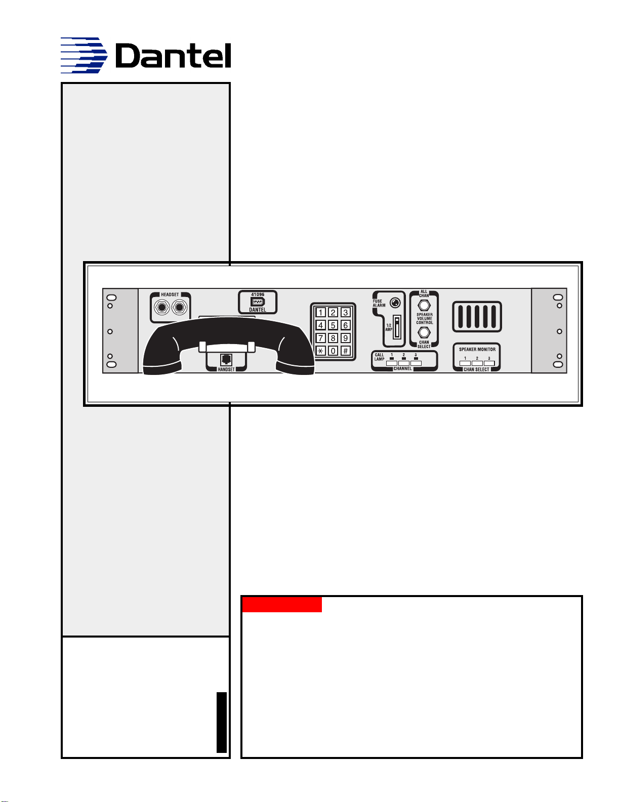
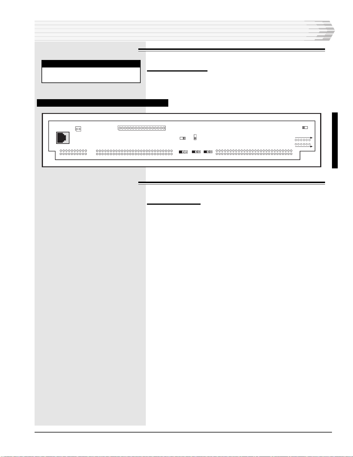
The 05547 Equipment Assembly is an order-wire system for
either voice or data communications.
The system consists of a 41096 Order-Wire Control and Speaker
Monitor Panel, 00330-02 Selective Signaling Order-Wire Termi-
nal, 46105 Dual VF 64-Kilobit Channel module, 44214 9600 BPS
Modem, a backplane with an M-lead driver, an optical coupler
circuit, and a clock-phase correction circuit to correct phase
problems between the 46105 and external equipment.

05547-0798<90-00047> PAGE 3
APPLICATION INFORMATION
Refer to Fig. 1 for an application drawing of the system.
FIG. 1 - 05547 APPLICATION
VOICE APPLICATION
The system operates as a standard order-wire when you pick up
the handset on the front of the 41096 panel and call someone at
a remote terminal. The voice circuit uses channel 1 of the
system.
44214
46105
MASTER (CALLED) TERMINAL
FIBER
TERMINAL
44214-00
or Other
External
9600 Baud
4-Wire Modem
05547-xx
REMOTE (CALLED) TERMINAL
05547-xx
00331-00 05723-01
DTSS3ON Order Wire
Off-Net Assembly
Network
Internet Shelf
Public
Switched
Telephone
Network
FIBER
OPTIC
TERM
FIBER
OPTIC
TERM
46105

PAGE 4 05547-0798<90-00047>
DATA APPLICATION
When you use the order wire system as a voice circuit, you dial a
preset number (station 1 code) to call someone at a remote
terminal. When you use the system as a data circuit, you dial a
different number (station 2 code) to call the same remote termi-
nal to set up a data communications path.
Here is how the data circuit works:
1. Select channel 1 on the 41096 panel, then pick up the handset and
call the remote terminal (station 2 code). At the remote end, the
00330 order-wire terminal answers your call and operates an
M lead driver that opens a communications channel through the
44214 9600 BPS Modem.
2. Select both channels 1 and 2 on the 41096 panel. This connects
your computer and external modem to the system. At the same
time the optical coupler (O.C.) circuit disables the sidetone in the
00330 order wire terminal so that the modem does not receive its
own data.
3. Hang up the handset and start sending or receiving digital data.
4. When you finish, press the # key to disconnect the modem at the
remote terminal. Release the channel 2 push button. You can ei-
ther release the channel 1 push button or leave it pushed in since it
is used for both voice and data communications.
OFF-NET APPLICATION
The 05547-03 option includes the B15-00331-00 DTSS3ON
Order Wire/PABX Interface (Off-Net) Assembly. This option
allows world-wide off-net access to virtually any telephone in the
world. The DTSS3ON allows any station in the order wire
system to dial an access line direct to a central office or through
a PABX, then dial out through the public-switched telephone
network (PSTN). In the same manner, an outside party can dial
into the order wire system and selectively dial any station
desired.
NETWORK INTERFACE APPLICATION
The 05547-04 option includes the A18-05723-01 Network Inter-
face shelf. Used in conjunction with the Off-Net shelf described
in the previous paragraph, the Network Interface Shelf allows
the user to access their network from a remote location on the
order wire system.
APPLICATION INFORMATION

05547-0798<90-00047> PAGE 5
INSTALLATION
This chapter consists of five sections which install and set up
the 05547-01. These sections are: Equipment Mounting,
Wiring, Switch and Strap Settings, Turn-Up Procedure, and
Troubleshooting. Follow these sections in order. Following those
are sections on the 00331 Off-Net Interface and the 05723
Network Interface Shelf.
All switch, strap, and level settings are factory-set.
EQUIPMENT MOUNTING
TOOLS REQUIRED:
Ohmmeter
Phillips screwdriver
To install the equipment assembly:
1. Set the assembly on a flat surface.
2. On the left side of the front panel of the assembly is a Phillips
screw. Turn the screw counterclockwise 90 degrees and open the
panel.
3. Carefully remove the 46105, 44214, 44020, 44022, and 49920 mod-
ules. All options and levels have been factory-set.
4. Visually inspect the shelf and modules for obvious damage.
5. Close the front panel of the assembly.
6. Use the ohmmeter to check for a short across the power input at
TB1-1 (negative battery) and TB1-3 (ground) on the rear of the top
(33337-00) equipment shelf. Refer to Fig. 2 for the location of TB1.
7. Refer to Fig. 3 and install the unit in your equipment rack. Hard-
ware is supplied in a bag attached to the side of the assembly.
Fasten the assembly in the rack with three Phillips screws
and lockwashers - two on the right side, and one on the lower
left side.
Fasten the upper left corner of the assembly with one ESD
stud and lockwasher. Make sure the stud is properly
grounded to the frame rail.
Place an ESD label next to the ESD stud.
From the rear of the rack, install the other ESD stud and
lockwasher in the frame rail, ensuring proper grounding of
the stud.
Place an ESD label next to the ESD stud.

PAGE 6 05547-0798<90-00047>
INSTALLATION
FIG. 3 - MOUNTING DIAGRAM
FIG. 2 - TB1 LOCATION
SIDE VIEW
FRONT
TOP
VIEW
FRONT "19 STANDARD MOUNT
SIDE VIEW
FRONT
"19 FLUSH MOUNT
TOP
VIEW
FRONT
"23 STANDARD MOUNT
TOP
VIEW
FRONT
SIDE
VIEW
FRONT
"23 FLUSH MOUNT
TOP
VIEW
FRONT
SIDE
VIEW
FRONT
UPDATED
J7
IN OUT
J5
J6
IN OUT
IN OUT
CAUTION: Do not reverse power
SYSTEM REAR VIEW
06
3
2
1
7
C5 U3 C6 U5
C4
C3
JP1
R6
R8
J6
155
256
55
F1
P2 16
7
19 1
20 2
J1
S2 12
PORT 2
TERMINATION
S3
OUT
IN
PORT 4
TERMINATION
P3
PHONE
JACK
J4
P1
J3
S1
BY-PASS
BRIDGE
IN
FB1 TB1
J3
T1
P3
R7
1
256
55
1
256
P4
R3
4
R2
3
2
1
R1
R4
6
7
R10
R11
15
81
25
13
14
19
4
1
J4 J5
J1
J2
2
1117
R9
01
02
R5
C1 C2
JP2
JP4
JP3
JP2
116 04
111
51
31
11
41
6
9
8
K2 15
8
9
1
1
2
3
(TB1)
FUSE
-BATT
ALM
GND
J2
1
256
55

05547-0798<90-00047> PAGE 7
WIRING
To wire the equipment assembly:
1. Wire the 46105 Dual VF 64-Kilobit Channel module to the fiber optic
terminal. Refer to the D18-05547-XX Block Diagram. Channel 1 is
labeled J6. Channel 2 is labeled J5. J1 can be used instead of J5 and
J6 if wire-wrap connections are preferred.
2. To use the assembly as a master data terminal, connect an external
202 modem (you must supply the modem) either to J3 (RJ-45 phone
jack) or to the wire-wrap pins at P4.
3. To use the assembly as a remote data terminal, connect the 25-pin
DB connector (C; also labeled J4) to a computer.
4. Wire the power as follows:
Wire ground to connection 3 of TB1.
Wire a visual or audible device to connection 2 of TB1. The
device will indicate when the fuse has blown. When the fuse
blows, connection 2 will have negative battery on it.
Wire negative battery (-21 to -56 VDC) to connection 1 of TB1.
5. End of this section.
FIG. 4 - EQUIPMENT WIRING
NOTE:
Do all wiring at the rear
of the assembly on the top
(33337-00) equipment
shelf. Refer to Fig. 4 and
the D18-05547-XX Block
Diagram.
INSTALLATION
UPDATED
Channel 2 Channel 1
1
2
3
(TB1)
SYSTEM REAR VIEW
06
3
2
1
(J1)
(C)
(P4)
1
8
9
1
1
8
9
1
JP1
J6
J2
P2
J1 S2
PORT 2
TERMINATION
S3
PORT 4
TERMINATION
P3
PHONE
JACK
J4
P1
J3
S1
J3
P3
J7
P4
(J3)
J5
J1
4
1
J2
1
256
55
J5J6
7
C3 C4 C5 U3 C6 U5
R6
R8
155
256
55
F1
16
7
19 1
20 2
12
OUT
OUT
IN
BY-PASS
BRIDGE
IN
FB1 TB1 T1
R7
1
256
R3
4R2
3
2
1
R1
R4
67
R10
R11
8
9
1
15
1
2
55
56
25
13
14
1
4
1
IN OUT
J4
25
1
14
1
1
56
55
IN OUT
IN OUT
2
1117
R9
01
02
R5
C1 C2
JP2
JP4
JP3
JP2
116 04
111
51
31
11
41
6
9
8
K2
15
8
9
1
FUSE
-BATT
ALM
GND

PAGE 8 05547-0798<90-00047>
SWITCH AND STRAP SETTINGS
33337-00 EQUIPMENT SHELF
To set the straps:
Refer to Fig. 5 for the location of the straps.
♦Set JP1 in the 1-2 position if the battery is -48 VDC.
♦Set JP1 in the 2-3 position if battery is -24 VDC.
Set JP2-JP5 to the 1-2 position to engage the Clock Phase Correc-
tion Circuit. This will correct clocking problems between the Data
Interface Shelf (05547) and the external device that the shelf
connects to. Set JP2-JP5 to the 2-3 position to bypass this circuit.
FIG.5 -STRAP LOCATION
NOTE:
All switch, strap, and level set-
tings are factory-set.
INSTALLATION
J7
IN OUT
JP4
JP3
JP2
JP5
JP5
J5J6
IN OUT
IN OUT
SYSTEM REAR VIEW
C3 C4 C5 U3 C6 U5
06
R6
R8
3
2
1
15
8
9
1
JP1
(C)
7
JP1
J6
155
256
55
F1
J2
P2
16
7
19 1
20 2
J1 S2
12
OUT
PORT 2
TERMINATION
S3
OUT
IN
PORT 4
TERMINATION
P3
PHONE JACK
J4
P1
J3
S1
BY-PASS
BRIDGE
IN
FB1 TB1
J3
T1
P3
R7
56
P4
R3
4
R2
3
2
1
R1
R4
6
7
R10
R11
15
8
9
1
15
8
9
1
1
3
1
3
2
1
2
J4 J5
J1
2
1117
R9
01
02
R5
C1 C2
116 04
1010 12
5
14
3
16
1
13
4
11
6
9
8
K2
1
256
55
25
13
14
1
4
1
JP4
JP3
JP2
3
2
1
J2
1
256
55
UPDATED

05547-0798<90-00047> PAGE 9
00330-02ORDER-WIRE TERMINAL SHELF
To set the switches:
Remove the back panel cover plate to verify that the switches are
set according to Fig. 6.
FIG. 6 - 00330-02 ORDER-WIRE SWITCH LOCATIONS
NOTE:
All switch, strap, and level set-
tings are factory-set.
INSTALLATION
41096 ORDER-WIRE CONTROL AND SPEAKER MONITOR PANEL
To set the straps:
Refer to Fig. 7 for the location of the straps.
1. Open the front panel of the unit.
2. Place the CTL LMT A strap in the IN position to prevent the ALL
CHAN volume control knob from turning off the speaker. Place the
strap in the OUT position to allow the volume control knob to turn
off the speaker.
3. Place the CTL LMT B strap in the IN position to prevent the CHAN
SELECT volume control knob from turning off the speaker. Place the
strap in the OUT position to allow the volume control knob to turn
off the speaker.
4. End of this section.
UPDATED
P2 16
7
19 1
20 2
J1 J2 S2 12
OUT
PORT 2
TERMINATION
S3
OUT
IN
PORT 4
TERMINATION
P3
PHONE
JACK
J4
P1
J3
S1
BY-PASS
BRIDGE
IN
1
256
55
2
1117
J7
IN OUT
J5
IN OUT
J6
IN OUT
1
256
55

PAGE 10 05547-0798<90-00047>
INSTALLATION
FIG. 7 - 41096 PANEL STRAP LOCATIONS
46105 DUAL VF 64-KILOBIT CHANNEL MODULE
To set the switches:
Refer to Fig. 8 for the locations of the switches.
1. Set S1 (BRDG) in RPTR.
2. Set S2 (LPBK 1) in OFF.
3. S101 (LPBK 2) in OFF.
To set the straps:
Refer to Fig. 8 for the locations of the straps.
1. Set the XMT CLK 1 and XMT CLK 2 straps in TERM.
2. Set the RCV CLK 1 and RCV CLK 2 straps in TERM.
3. Set the RCV DATA 1 and RCV DATA 2 straps in TERM.
4. Set the M LEAD 1 and M LEAD 2 straps in YES.
5. Set the MODE strap in RPTR.
6. Reinstall the module in the left slot in the top equipment shelf.
7. End of this section.
NOTE:
All switch, strap, and level
settings are factory-set.
NOTE:
If an external clock is not
used, strap XMT CLK 1
and XMT CLK 2 to TTL+.
NOTE:
To strap the module for
terminal mode, set switch
S1 to TERM and place the
MODE strap in TERM.
IN

05547-0798<90-00047> PAGE 11
FIG. 8 - 46105 SWITCH AND STRAP LOCATIONS
MODE
E LEAD
TERM RPTR
NO YES
LPBK 1
OFF ON
LPBK 2
BRDG
CHANNEL
2
CHANNEL 1
M LEAD 2
OFF ON
DATA
CLK
CLK
RCV
RCV
XMT
NO
NC
DATA
RCV
TM
T-
T+
TM
T-
T+
TERM
RPTR
S101
S2
S1
T
T
L
T
E
R
M
RCV
DATA
T
T
L
-
T
T
L
+
T
E
R
M
RCV CLK
T
T
L
-
T
T
L
+
T
E
R
M
XMT CLK
Y
E
SN
O
M LEAD
N
CN
D
E LEAD
INSTALLATION

PAGE 12 05547-0798<90-00047>
44214 9600 BPS MODEM
To set the switches and straps:
Refer to Fig. 9 for the locations of the switches and straps.
1. On the front panel of the module, set the ALB and DLB switches (S3
and S5) in the DOWN positions.
2. On the circuit board, set the 2W/4W switch (S7) for 4W.
3. Set S2 and S6 on the circuit board as follows:
S2-1 off, rest on (9600 baud operation)
S6-1 off, rest on (TTL/CMOS I/O port enabled)
4. Set JP1-JP3 to the O (OUT) position. Set JP4 and JP5 to the ACT
position.
5. Reinstall the module in the middle slot in the top equipment shelf.
6. End of this section.
NOTE:
The 44214 communicates
with a second 44214 at the
other end. One of these two
modules must have its ORG/
ANS switch set for ORG and
the other module must be
set for ANS.
NOTE:
Switches 1, 3, 4, 5, and Level
Controls R44 and R53 are ac-
cessible through the front
panel.
INSTALLATION
FIG. 9 - 44214 SWITCH AND STRAP LOCATIONS
NOTE:
All switch, strap, and level
settings are factory-set.
S7
R53
S3
S5
S1
S4
OUT
IN
JP1
OUT
IN
JP2
OUT
IN
JP3
ACT
N/A
JP4
ACT
N/A
JP5
4W
2W
ON
R44
S6
1234
OFF
S2
1234
OFF
ON
44214-00
4-WIRE MODEM
A11-44214-00 REV. _
LINE
MON
LINE
MON
TD RD
RTS CD
DTR CTS
2W
XMT
4W
XMT
RCV
LEVEL
GND
ON
OFF
ON
OFF
ORG
ANS
RCV
ALB
DLB
RST

05547-0798<90-00047> PAGE 13
44020 DTMF DECODER WITH 49018 STATION SELECTOR
SUBASSEMBLY
To set the switches and straps:
1. Verify that the switches and straps are set according to Figs. 10 and
11.
2. On the 49018 subassembly, set the station 1 code with S1, S2, and
S3. S1 is the first digit. Use this code to call this order wire terminal
for voice communications.
3. On the 49018 subassembly, set the station 2 code with S4, S5, and
S6. S4 is the first digit. Use this code to call this order wire terminal
when it is a remote data terminal.
4. Reinstall the module in the left slot of the bottom equipment shelf.
5. End of this section.
FIG. 10 - 44020 STRAP LOCATIONS
INSTALLATION
A
B
C
D
E
NORMAL
REVERSE
1
12
J1
1
12
J2
C2
#2
A2
2
C1
#1
A1
1
16
DGT
12
0DB +10DB
-10DB
IN DTF
OUT BRDG
600 OHM
OR A # OR CCLR
EXT
CLR PLS EXT
CLR

PAGE 14 05547-0798<90-00047>
FIG. 11 - 49018 SWITCH AND STRAP LOCATIONS
44022 STATION INTERFACE MODULE
To set the straps:
1. Verify that the straps are set according to Fig. 12.
2. Reinstall the module in the middle slot of the bottom equipment shelf.
3. End of this section.
FIG. 12 - 44022 STRAP LOCATIONS
SIDE TONE
IN OUT
IN OUT
10dB XMT
PRIVACY
REMOTE
M LEAD
OUT
IN
OUT
IN
OUT
IN
ALL
GRP
RCV PAD
OUT
IN
RG
600 OHM
600 OHM
0 OHM
0 OHM
4W
4W 2W2W
INSTALLATION
*
A
C
*
CKT 2
X2
X1
X6
12
P1
P2
1
12
S1
S2
S3
S4
S5
S6
IN
OUT
1 DIGIT
2 DIGIT
3 DIGIT
RESET
CLR (X5)
#
SET(X4)
1
CKT 1
0/1
49018-00
STATION
SELECTOR
CKT 1
CKT 2
0/1
OPTIONAL
SETTING
#

05547-0798<90-00047> PAGE 15
49920 INTERRUPT-SUPPLY MODULE
To set the switches and straps:
1. Verify that the switches and straps are set according to Fig. 13.
2. Reinstall the module in the right slot of the bottom equipment
shelf.
FIG. 13 - 49920 SWITCH AND STRAP LOCATIONS
S2
ON
OFF
OFF
TEST
ON
EXT
SPK
AUTO
S1
Access
S1
from
Front INTERRUPT
STRAPS
NORM
REV
RING-BACK
TONE STRAPS BUZZER
TURN-UPPROCEDURE
Check the tone levels of the external modem:
1. Apply power to the order wire system.
2. Push in the CHANNEL 1 and 2 buttons on the front of the 41096.
3. Connect a 600-ohm dB meter (bridging) to the XMT MON jack on the
front panel of the 44022 Station Interface module.
4. Turn on the carrier signal on the external modem.
5. Adjust the transmit level on the modem until the dB meter reads
-13 dB.
6. Turn off the carrier signal on the modem.
7. Remove the dB meter.
8. Release the CHANNEL 1 and 2 buttons on the front of the 41096.
9. Set up the external modem to receive a signal of -26 dB.
10. End of this section.
INSTALLATION

PAGE 16 05547-0798<90-00047>
Check the system.
The order wire system is aligned at the factory. Once installed, it
is ready to operate.
Follow the procedures in the Operation chapter to check the
system as a voice circuit and as a data circuit.
Adjusting Signal Levels
Follow the procedures below if you have to check signal levels or, if
you install replacement equipment, to set the levels.
ORDER-WIREALIGNMENT
To check or set signal levels:
1. Remove power from the order wire system.
2. Remove the 46105 module and place switch S2 (LPBK 1) in the ON
position. Refer to Fig. 8 in the Installation chapter for the location of
the switch. Reinstall the module.
3. Apply power to the order wire system.
4. Connect a 600-ohm load across the signal output of a 600-ohm signal
generator. Set the generator for 1004 Hz and a level of 0 dB. Remove
the 600-ohm load and connect the generator to the XMT DROP jack
on the 44022 module.
5. Connect a 600-ohm dB meter (bridging) to the channel 1 XMT MON
jack on the front panel of the 46105 module.
6. Adjust the transmit level on the front of the 44022 module for a read-
ing of -16 dB.
7. Move the dB meter (bridging) to the channel 1 XMT LVL pin jacks on
the front of the 46105 module.
8. Adjust the channel 1 transmit level on the front of the 46105 module
for a reading of 0 dB.
9. Move the dB meter (bridging) to the channel 1 RCV MON jack on the
front panel of the 46105 module.
10. Adjust the channel 1 receive level on the front of the 46105 module for
a reading of +7 dB.
11. Terminate the dB meter with 600 ohms and move it to the RCV
DROP jack on the 44022 module.
12. Adjust the receive level on the front of the 44022 module for a reading
of -13 dB.
13. Remove the signal generator and dB meter.
14. Remove power from the order-wire system.
15. Remove the 46105 module and place switch S2 (LPBK 1) in the OFF
position. Reinstall the module.
INSTALLATION
NOTE:
All switch, strap, and level
settings are factory-set.
CONTINUED . . .

05547-0798<90-00047> PAGE 17
16. Proceed to the next section to align the 44214 modem, or apply power
to the system and follow the procedures in the Operation chapter to
check the system.
44214 MODEM ALIGNMENT
Set modem to Originate Mode
Set Switch 4, accessible through the front panel, to ORG.
Adjust transmit level
1. Connect a 600 ohm terminated dB meter to the module. Connection
can be made at either of two places. A mini-plug can be inserted into
the front panel jack labeled 4W MON or the meter can be connected
to the 44214s edge connector at pins 40 and 39.
2. Adjust the XMT LEVEL, at the bottom of the front panel, until the
meter reads -6dBm.
Adjust the receive level
1. Connect a 600 ohm load across the output of a signal generator. With
a 600 dB meter across those same outputs, adjust the output level of
the generator until the meter reads -29 dBm, at 1004 Hz.
2. Remove the meter and the 600 ohm load from the generator. Connect
the generator to the 44214. Connection can be made at either of two
places. A mini-plug can be inserted into the front panel jack labeled
2W LINE or the meter can be connected to the 44214s edge connector
at pins 41 and 42.
3. Connect the dB meter, unterminated, to the pinjacks on the front
panel. These are labeled RCV and GND.
4. Adjust the RCV LEVEL, at the bottom of the front panel, until the
meter reads -20 dBm.
5. Remove the meter and the generator.
00331-00 OFF-NET INTERFACE
This shelf is part of the D18-05547-03. Fig. 14 shows the front
view of this shelf.
INSTALLATION
FIG. 14 - 00331 FRONT VIEW

PAGE 18 05547-0798<90-00047>
Verify that the switches and straps are set as shown in Figs. 15-18
and Table A.
Wiring
Connect the 00331 Off-Net Interface to the 05547 Assembly. Refer
to page 3 of 6 of the D18-05547-XX Block Diagram.
INSTALLATION
FIG. 15 - 44020 DTMF DECODER STRAP SETTINGS
FIG. 16 - 49018 STATION SELECTOR SUBASSEMBLY SWITCH AND STRAP SETTINGS
*
A
C
*
CKT 2
X2
X1
X6
12
P1
P2
1
12
S1
S2
S3
S4
S5
S6
IN
OUT
1 DIGIT
2 DIGIT
3 DIGIT
RESET
CLR (X5)
#
SET(X4)
1
CKT 1
0/1
49018-00
STATION
SELECTOR
CKT 1
CKT 2
0/1
OPTIONAL
SETTING
#
UPDATED
A
B
C
D
E
NORMAL
REVERSE
1
12
J1
1
12
J2
C2
#2
A2
2
C1
#1
A1
1
16
DGT
12
0DB +10DB
-10DB
IN DTF
OUT BRDG
600 OHM
OR A # OR CCLR
EXT
CLR PLS EXT
CLR

05547-0798<90-00047> PAGE 19
INSTALLATION
FIG. 17 - 44023 PABX/TRUNK INTERFACE STRAP SETTINGS
44023-00
PABX/TRUNK
INTERFACE
BUSY
INC CALL
OFF HOOK
TRANSMIT
LINE
DROP MON
TEST RST
LINE
DROP MON
RECEIVE
DIST
DIST
GND
GND
A11-44023-00 REV__
INC CALL LED
OFF HOOK LED
XMT LEVEL
ADJUST
RCV LEVEL
ADJUST
GND
START
LP
CONT
M LEAD
BATTERY
CONF
E CONT
IN
OUT
IN
OUT
IN
OUT
OUT
IN
IN OUT
IN OUT
BUSY LED
M LEAD GROUND
IN
OUT
PRIVACY
BUSY CONTROL
IN
OUT
RCV PAD
IN OUT
XMT PAD
IN OUT
R73
R24
R5

PAGE 20 05547-0798<90-00047>
FIG. 18 - 44443 FOUR-WIRE TERM SET SWITCH AND STRAP SETTINGS
INSTALLATION
A11-44443-00
44443-XX
TERM SET
RCV ATTEN (dB)
OUT IN OUT IN
4 WIRE LINE
XMT RCV
2 WIRE DROP
XMT RCV
XMT ATTEN (dB)
OUT IN OUT IN 18
ON
OPEN
600
900
S2
600
900
S1
S3
AB CAP B INT
BYPASS
A INT
BYPASS
IN
OUT
IN
OUT
IN
OUT
This manual suits for next models
4
Table of contents
Other Dantel Recording Equipment manuals
Popular Recording Equipment manuals by other brands

Black Lion Audio
Black Lion Audio Revolution 2x2 quick start guide

QSC
QSC ATTERO TECH AXON D2i user manual

Advantech
Advantech ADAM 4100 user manual

White Rodgers
White Rodgers 1F98EZ-1621 Homeowner user guide

360 Systems
360 Systems Short/cut 2000 Audio Editor owner's manual

Mackie
Mackie MDR 24/96 Service manual