Dark Matter DMP0144 User manual

dark matter composites ltd
t+44 (0)1582 791001 www.darkmattercomposites.com
Unit 8 Redbourn Industrial Estate, High Street, Redbourn, Hertfordshire, AL3 7LG, UK
Registered in England & Wales No: 5395870
‘Large Air Router’
Product Code - DMP0144
USER MANUAL
Contents
User & Warranty Information..............................................................................2
Dynabrade ‘EC Machinery Directive, Declaration of Conformity’........................3
Dynabrade ‘Technical Data Sheet Tool E8816’..................................................4
Dynabrade PD09.56 ‘Air Tool Manual - Safety, Operation and Maintenance’....5
1. Zero Adjustment of Routing Bits..................................................................13
2. Depth Adjustment of Routing Bits................................................................14
Depth Adjustment.......................................................................................15
3. Using the Standard Router Base.................................................................15
Special Notes.............................................................................................16
Using the Standard Router Base................................................................17
4. Cleaning & Maintenance..............................................................................18
5. Compatible Portable Extraction ...................................................................20
Advice for Dust Free Operations................................................................20

DMP0144, Large Air Router
USER MANUAL
© Dark Matter Composites Ltd
Page 2 of 21
t+44 (0)1582 791001 www.darkmattercomposites.com
Unit 8 Redbourn Industrial Estate, High Street, Redbourn, Hertfordshire, AL3 7LG, UK
Registered in England & Wales No: 5395870
User & Warranty Information
IMPORTANT USER &
WARRANTY INFORMATION
PLEASE READ IN FULL PRIOR TO USE
The Dark Matter Composites ‘Step Sanding Tool Kit’ has been designed as a repair solution
and comprises of a modified Dynabrade Air Router and a Tool Kit designed specifically for
preparing step sanded repair surfaces in composite materials/parts and preparation of cured
composite surfaces for co-bonding and secondary bonding operations.
Prior to use, please read all ‘Dynabrade’ and ‘Dark Matter Composites’ documentation
provided with this ‘Step Sanding Tool Kit’ and within this User Manual in full. No part of
this kit can be considered ‘typical’ or ‘independent’ from the tool kit as a whole. The
following documents are provided in the document holder in the lid of the case:
Dynabrade, Pneumatic Tool Safety Operating Guidelines
Dynabrade, Industrial Pneumatic Tools Lifetime Warranty
Dynabrade, Required Tool Maintenance
Dynabrade, Operating, Maintenance and Safety Instructions
Dark Matter Composites Ltd, Step Sanding Tool Kit User Manual (this document)
Dark Matter Composites Ltd, Step Sanding Tool Kit Price List (includes spares)
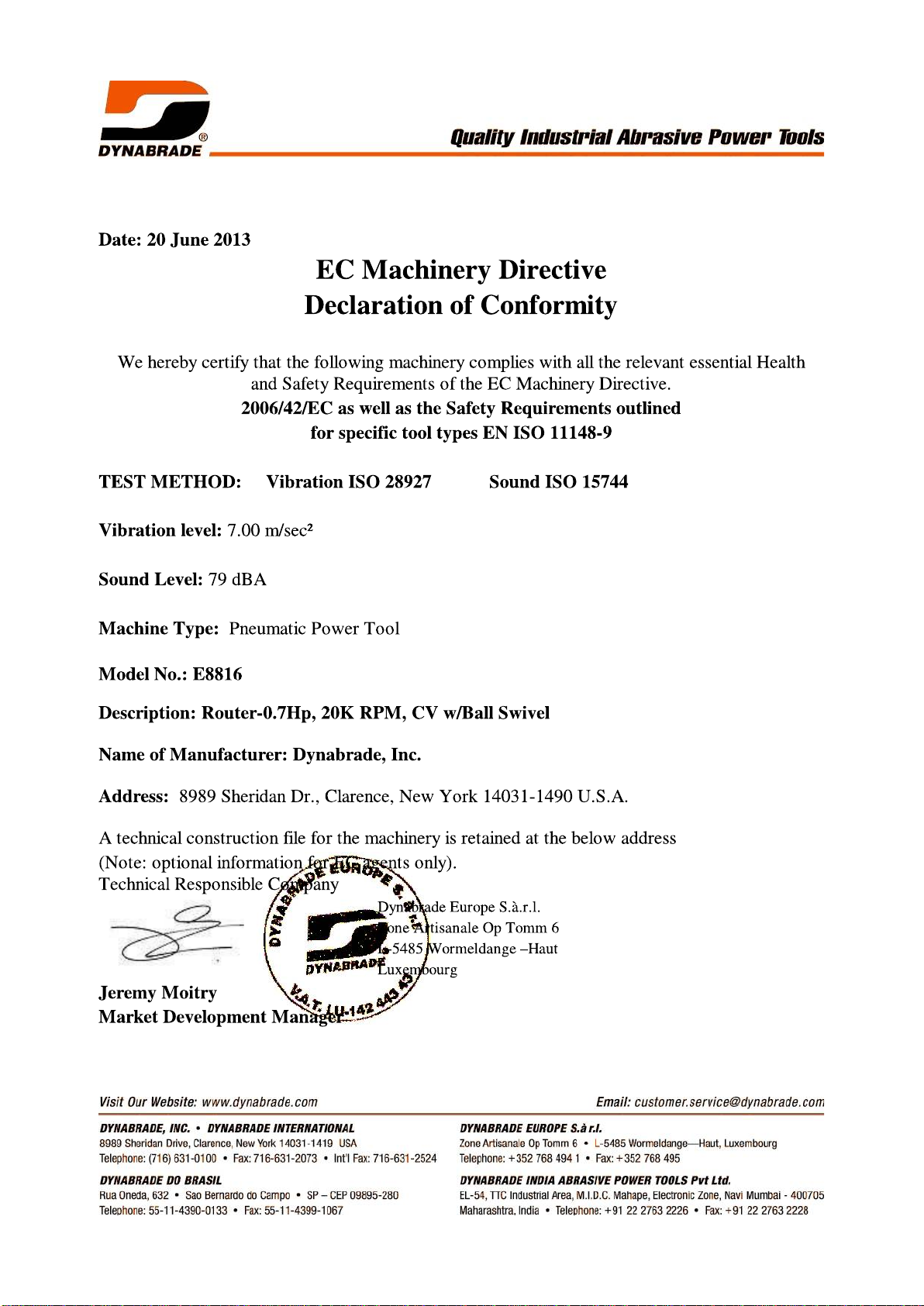
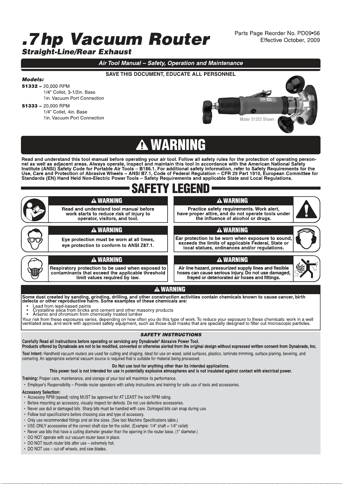
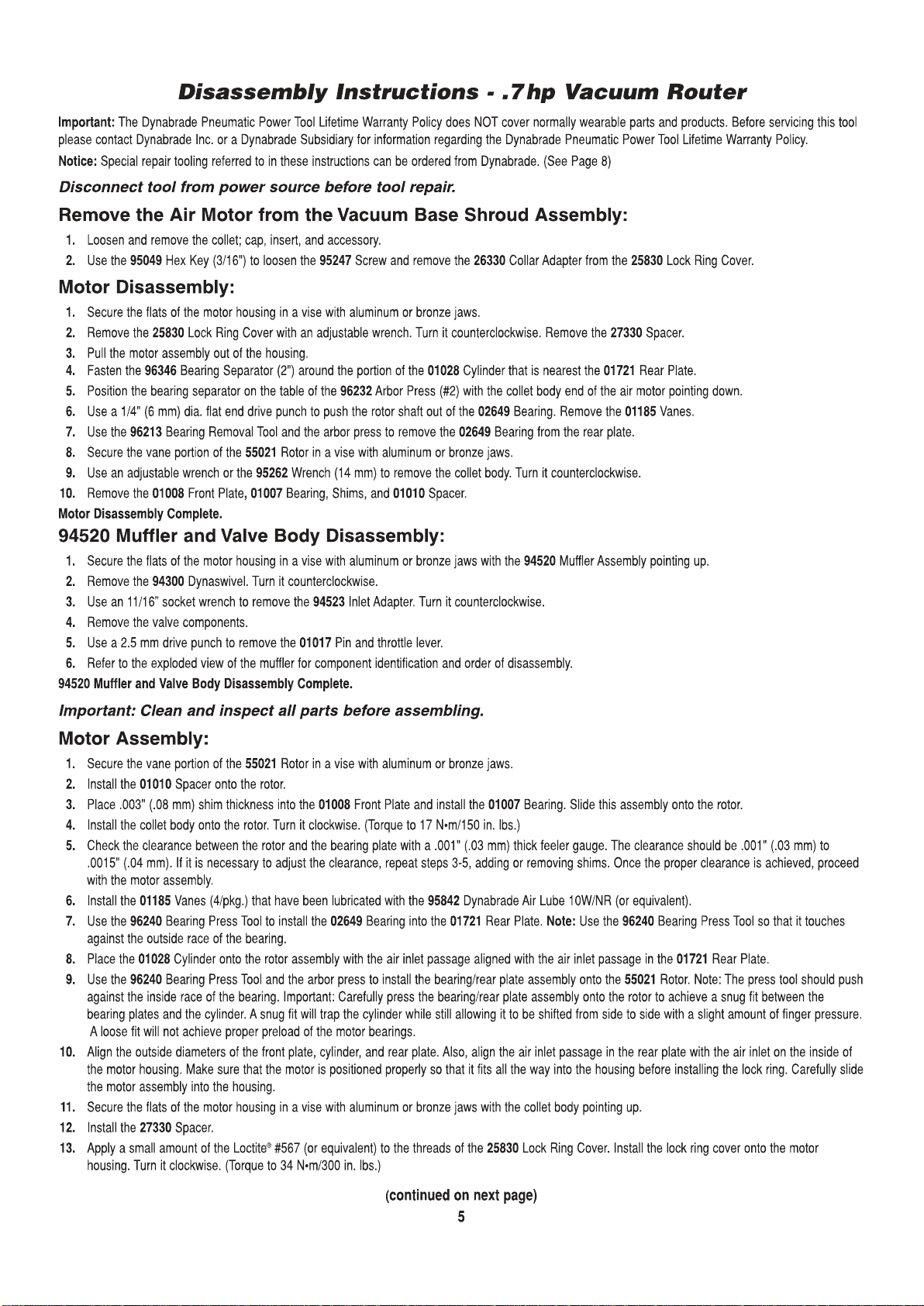
The Dynabrade Air Router supplied as part of the kit is specified uniquely to Dark Matter
Composites Ltd as Model No. E8816. The Dynabrade manual PD0956 ‘Air Tool Manual -
Safety, Operation and Maintenance’ for the Model 51333 is applicable to the model supplied as
part of this kit as well as the instructions related directly to the ‘Step Sanding Tool Kit’ in this
manual.
The instructions provided within this ‘User Manual’ are in addition to the Dynabrade
documentation included within the ‘Step Sanding Tool Kit’ and this ‘User Manual’.
Note that the E8816 model can be used as the 51333 model using the parts identified in green
on the parts list on Page 3 of this manual to make up the vacuum base shown on Page 4 of the
Dynabrade manual PD0956.
This tool kit has also been designed to be used in conjunction with a suitable portable/mobile
dust extraction unit suitable for use with ‘on-tool’ dust extraction. Dark Matter Composites
provides a range of dust extraction units that are compatible with this tool kit. Assessment of
the suitability and end use of third party extraction units is the sole responsibility of the
purchaser.
Use of this tool kit outside of the applications identified or the instructions provided within this
user manual are not covered by the warranty.
In order to provide a full product support service, Dark Matter Composites offers training
courses on how to use and get the best from the tool kit as well as a full range of
recommended electric and air driven portable dust extraction units.


DMP0144, Large Air Router
USER MANUAL
© Dark Matter Composites Ltd
Page 13 of 21
t+44 (0)1582 791001 www.darkmattercomposites.com
Unit 8 Redbourn Industrial Estate, High Street, Redbourn, Hertfordshire, AL3 7LG, UK
Registered in England & Wales No: 5395870
1. Zero Adjustment of Routing Bits
SAFETY NOTICE - Always disconnect the air supply to the air router prior to fitting or
adjusting any part of the air router/jig assembly.
Whenever the cutting head or jig is changed, the zero must be
reset on the router/jig assembly as follows:
1. Fit the required routing bit as detailed on page 6 of this
manual.
2. Remove the three screws from the vacuum base.
3. Fit the required jig/router base and secure with the three
screws.
4. Hand tighten the screws with the screwdriver provided. Do
NOT over tighten the screws as this may lead to the threads
being damaged.
5. Disconnect the top of the vacuum flexible hose.
6. Loosen the locknut with the 1½” spanner provided.
7. Stand the router/jig assembly face
down on a flat surface and press the
vacuum base firmly against the flat
surface.
8. Rotate the router body clockwise until
the cutter makes contact with the flat
surface. A slight resistance in the
rotation of the router body should be
felt at this point.
9. Without moving the router/jig assembly, tighten the locknut
with the 1½” spanner provided.

DMP0144, Large Air Router
USER MANUAL
© Dark Matter Composites Ltd
Page 14 of 21
t+44 (0)1582 791001 www.darkmattercomposites.com
Unit 8 Redbourn Industrial Estate, High Street, Redbourn, Hertfordshire, AL3 7LG, UK
Registered in England & Wales No: 5395870
10. Lift the router/jig assembly and check the routing bit is level
with the jig base using a straight edge.
11. If required, loosen the locknut, make any fine adjustments
necessary and tighten the locknut.
12. Hold the exhaust assembly
(not the vacuum connection)
and air router firmly and rotate
the exhaust assembly to align
the vacuum connection with
the vacuum flexible hose.
13. Reconnect the vacuum flexible
hose.
14. Using a fine permanent marker, mark a vertical line on the
collar adaptor in line with the scaled edge of the pointer.
15. Using a fine permanent
marker, mark a horizontal line
on the scale pointer in line with
the central scale line on the
collar adaptor.
2. Depth Adjustment of Routing Bits
SAFETY NOTICE - Always disconnect the air supply to the air router prior to fitting or
adjusting any part of the air router/jig assembly.
The collar adaptor is engraved with two laser engraved scales:
The upper scale is in small increments of 0.05mm (≈ 0.002”)
The lower scale is in larger increments of 0.25mm (≈ 0.010”)
Depth adjustment is achieved using a 1.5mm metric thread pitch (≈ 0.059”) on the router
collar adaptor. Note that 0.001” of depth is lost per full thread due to conversion from metric
to imperial. If required, make allowance for this when depth cutting in imperial.

DMP0144, Large Air Router
USER MANUAL
© Dark Matter Composites Ltd
Page 15 of 21
t+44 (0)1582 791001 www.darkmattercomposites.com
Unit 8 Redbourn Industrial Estate, High Street, Redbourn, Hertfordshire, AL3 7LG, UK
Registered in England & Wales No: 5395870
Depth Adjustment
1. Stand the router/jig assembly face down on a flat
surface.
2. Disconnect the top of the vacuum flexible hose.
3. Loosen the locknut with the 1½” spanner provided.
4. Rotate the collar adaptor/router assembly:
Clockwise to increase the cutter depth
Anti-clockwise to reduce the cutter depth
Use the laser engraved scales and zero marks for
reference.
5. Tighten the lock nut with the 1½” spanner.
6. If required, the air router trigger position can be
adjusted as follows:
Loosen the collar adaptor grub screw using the 1/8” allen key
Rotate the router body to the desired position
Ensure the router body is firmly seated in the collar adaptor and tighten the collar
adaptor grub screw using the 1/8” allen key
Note that this does not change the depth of the cutter
7. Hold the exhaust assembly
(not the vacuum connection)
and air router firmly and rotate
the exhaust assembly to align
the vacuum connection with
the vacuum flexible hose.
8. Reconnect the vacuum
flexible hose.
3. Using the Standard Router Base
The Standard Router Base can be used to route
surfaces either free hand or to follow guide jigs (not
included with this kit).

DMP0144, Large Air Router
USER MANUAL
© Dark Matter Composites Ltd
Page 16 of 21
t+44 (0)1582 791001 www.darkmattercomposites.com
Unit 8 Redbourn Industrial Estate, High Street, Redbourn, Hertfordshire, AL3 7LG, UK
Registered in England & Wales No: 5395870
Special Notes
The standard router base
rests against the part
surface, using it as a
reference surface in terms
of depth. As material is
removed, part of the router
base may become
suspended above the part
surface. Provided the user
only presses down on the
router base where it makes
contact with the part
surface, the cutter will
remain in the correct
position. Undue load on the
router body while part of the
router base is suspended above the part surface will tip the router body and cut irregularities in
the surface. The air router must be used as a router and not as a sanding or grinding tool.
Guide Jig Design
The outer edge of the standard router
base can be used to rest against the edge
of a guide jig.
Guide jigs and their sequence of use need
to be designed to use the part surface as a
reference surface.
The diameter of the standard router base
is 4” / 101.5mm.
Subtract the diameter of the cutter from
the diameter of the routing base and half
the result to obtain the offset for the cutter.
Ø4” / 101.6mm

DMP0144, Large Air Router
USER MANUAL
© Dark Matter Composites Ltd
Page 17 of 21
t+44 (0)1582 791001 www.darkmattercomposites.com
Unit 8 Redbourn Industrial Estate, High Street, Redbourn, Hertfordshire, AL3 7LG, UK
Registered in England & Wales No: 5395870
Below are the dimensions of the router base and typical mounting plate requirements.
If required, please contact Dark Matter Composites for advice on jig design.
SAFETY NOTICE - Always disconnect the air supply to the air router prior to fitting or
adjusting any part of the air router/jig assembly.
Using the Standard Router Base
1. Select and fit the routing bit required as detailed on page 6 of this manual..
2. Zero the cutter as detailed in section 1.
3. Set the depth of the cutter (as detailed in section 2) to the depth associated with material
removal operation.
4. Check and adjust the position of the part and ensure it is suitably supported and clamped as
necessary.
5. Check and adjust the position of the router trigger as necessary (as detailed in section 2,
step 6).
6. Connect the compressed air supply hose and vacuum extraction unit hose to the air router
connections.
7. Ensure that the weight of the air and vacuum hoses are fully supported above the
tool using a suitable hanger/support boom. Any side load or restriction applied to
the air router during operation may result in the router tipping and the cutter digging
into the surface of the part.
Ø33mm(1¼”)
Jig Mounting Holes for 8/32” UNC
Countersunk Machine Screw
Ø4.6 (3/16”) HOLES, 2” PCD
Ø9x3 (3/8”x1/8”) COUNTERBORE
Ø9x90° (3/8”x90°) CSK
Ø9x90° CSK
x3 mounting threads
8/32” UNC, 2” PCD
Ø63mm(2½”)
24mm(15/16”)
R10mm(3/8”)

DMP0144, Large Air Router
USER MANUAL
© Dark Matter Composites Ltd
Page 18 of 21
t+44 (0)1582 791001 www.darkmattercomposites.com
Unit 8 Redbourn Industrial Estate, High Street, Redbourn, Hertfordshire, AL3 7LG, UK
Registered in England & Wales No: 5395870
8. Lift the router just clear of the part surface so that it does not make contact with the part and
gradually depress the trigger. Check the correct operation of the air router and gradually
increase the speed to check correct operation over the full speed range and then cease
operation of the air router.
9. If there is any problem with the setup of the air router or any unusual imbalance or vibration
present, cease operation of the air router immediately. Disconnect the compressed air
supply and fully check the setup and configuration of the equipment. If required, remove
the equipment from service and conduct repair/maintenance activities on the equipment as
required.
10. If the air router operates correctly, continue with the material removal activity.
11. Ensure that the vacuum extraction connected to the air router is running prior to
starting the air router.
12. Lift the router just clear of the part surface so that it does not make contact with the part and
depress the trigger to operate the air router.
13. Where the standard router base is used for free hand material removal, press the router
base against the part surface to cut down into the part surface.
14. Where the standard router base is used to follow a guide jig, rest the edge of the router
base against the guide jig and the press the router base against the part surface to cut
down into the part surface.
15. Take care to ensure that the router base is pressed against the part surface where it is
supported by the part surface, not where it is unsupported.
16. Move the router base in a slow and controlled manner, allowing the side of the cutting head
to remove material in a controlled manner. Do NOT operate the router in a swinging
motion, back and forth motion or too fast as the cutter will rise up the material and not cut to
the required depth.
17. Repeat steps 4 to 17 and continue to remove material as required.
4. Cleaning & Maintenance
When used with a suitable portable/mobile dust extraction unit for use with ‘on-tool’ dust
extraction, dust generation outside the shroud assembly is negligible when used correctly.
However, components within the shroud assembly become dust contaminated during each use.
In addition to the Dynabrade Maintenance Instructions included in this manual, the following
cleaning and maintenance activities should be followed.
Router Bases & Fittings
Clean all router bases and associated fittings with clean water and a microfibre cloth to
remove any dust/debris from the surface of the parts and contaminated threaded fittings.
Ensure the router bases and fittings are completely dry prior to being stored.
Do NOT use solvents or detergents to clean the router bases and associated fittings as
these may damage the jigs and remove the filled engravings.

DMP0144, Large Air Router
USER MANUAL
© Dark Matter Composites Ltd
Page 19 of 21
t+44 (0)1582 791001 www.darkmattercomposites.com
Unit 8 Redbourn Industrial Estate, High Street, Redbourn, Hertfordshire, AL3 7LG, UK
Registered in England & Wales No: 5395870
Router Assembly
The following parts of the router assembly become contaminated with dust during each use.
To clean the collet and shroud assemblies and collar adaptor:
Disassemble these parts as stated in the Dynabrade Maintenance Instructions.
Mineral spirits are recommended for cleaning these parts.
Where required use a soft brush to loosen dust from the parts.
Dry with lint free tissue.
Reassemble as stated in the Dynabrade Maintenance Instructions.
Do NOT clean with any solvents or oils containing acids, esters, ketones, chlorinated
hydrocarbons or nitro carbons.
Do NOT clean with chemicals that have a low flash point (for example: acetone, WD40).
To clean the vacuum swivel assembly:
Use clean water and a microfibre cloth to remove any dust/debris from the internal and
external surfaces of the assembly.
Ensure the parts are completely dry prior to being stored.
Do NOT use solvents or detergents as these may damage the parts.
To clean the vacuum hose:
Rinse under clean running water to remove any dust/debris from the internal and
external surfaces of the hose.
Where required use a soft brush to loosen dust from the part.
Ensure the hose is completely dry prior to being reassembled.
Do NOT use solvents or detergents as these may damage the part.
Shroud
assembly
Vacuum
hose
Routing Bit
(not included)
Collar adaptor
Vacuum
swivel
assembly
Collet
assembly

DMP0144, Large Air Router
USER MANUAL
© Dark Matter Composites Ltd
Page 20 of 21
t+44 (0)1582 791001 www.darkmattercomposites.com
Unit 8 Redbourn Industrial Estate, High Street, Redbourn, Hertfordshire, AL3 7LG, UK
Registered in England & Wales No: 5395870
5. Compatible Portable Extraction
This air tool kit has been specifically designed to be used with a compatible portable extraction
unit. The combination of a lightweight Dynabrade air motor with a bespoke vacuum shroud and
bespoke cutters requires very specific extraction.
Advice for Dust Free Operations
This advice applies specifically to the use of this air tool kit.
We recommend the use of extraction that auto-starts with the air motor operation.
We recommend the use of extraction with a ‘low airflow alarm’.
Operational conditions:
For routing bits, set the air tool speed to 12,000-15,000rpm (approx. half speed)
For surface planers, set the air tool speed to the full 20,000rpm
Extractor requirements = 5m3/hr at 5,000Pa
For our portable dust extraction unit DMP0120, use:
Hose size setting ‘16’
Variable airflow at the minimum
The second cleaning hose and brush must also be connected and open to allow the
airflow to be reduced accordingly.
For our portable dust extraction unit DMP0123:
Set the combined air pressure to for the extractor and air tool to 6 Bar / 80psig
The second cleaning hose and brush must also be connected and open to allow the
airflow to be reduced accordingly.
During extensive trials, no airborne dust was present with the materials listed below. In some
cases, small localised debris between 1-4mm maybe projected locally, which falls but does not
become airborne. The presence of debris varies dependant upon the quality of the laminate
and the feed rate used. We have much more information available, please contact us to
discuss your requirements.
This manual suits for next models
2
Table of contents