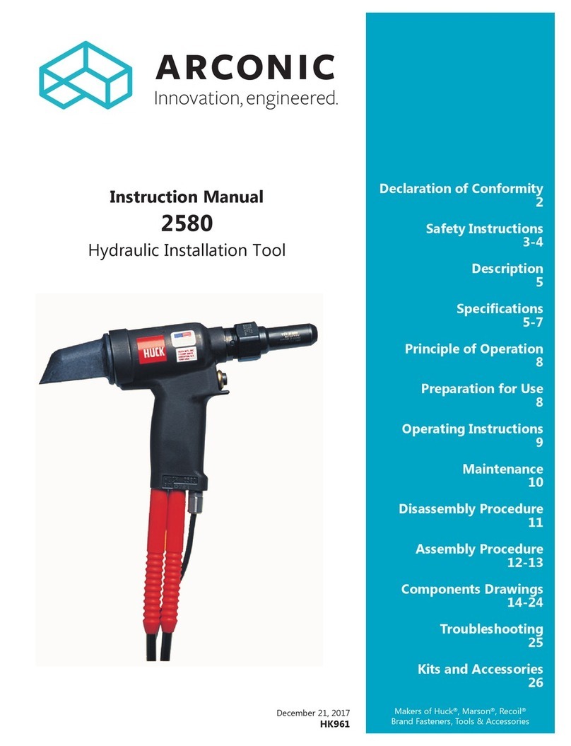
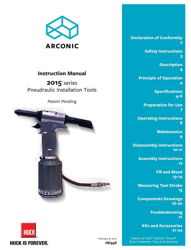
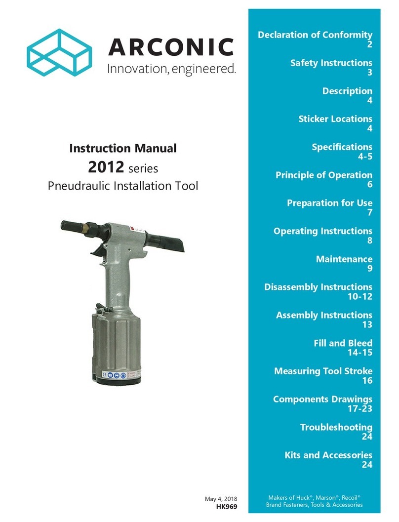
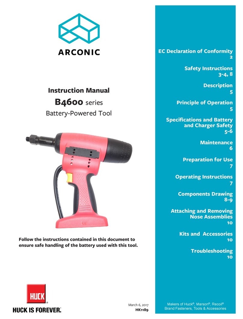
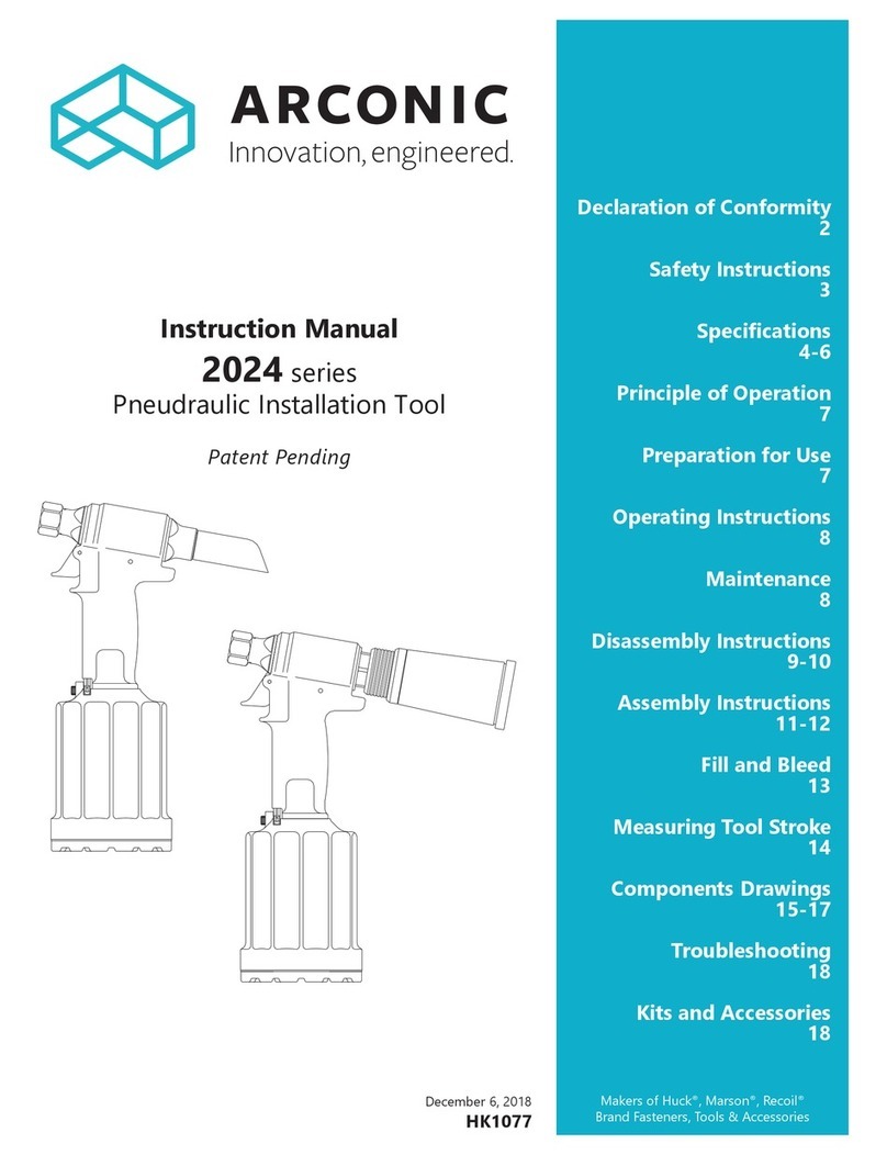
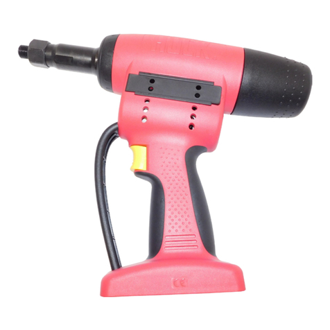
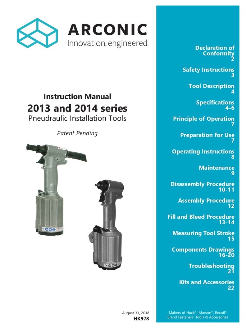
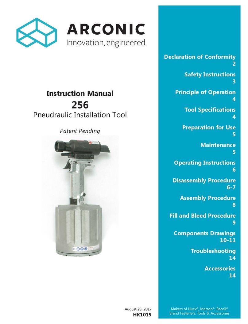
Arconic DT4600 User manual

Patent Pending
October 24, 2017
HK1174
Makers of Huck®, Marson®, Recoil®
Brand Fasteners, Tools & Accessories
Instruction Manual
DT4600
Pneudraulic Installation Tool
HUCK DREAM TOOL™
Declaration of Conformity
2
Safety Instructions
3
Specications
4
Principle of Operation
5
Preparation for Use
5
Nose Assembly/Fastener
Compatibility
6
Attaching and Removing a
Nose Assembly
6
Operating Instructions
7
Maintenance
7
Disassembly Procedure
8
Assembly Procedure
8
Fill and Bleed
9
Components Drawings
10-12
HUCK DREAM TOOL is a registered trademark of Arconic Inc.

2
DT4600 Pneudraulic Installation Tool (HK1174)

3
DT4600 Pneudraulic Installation Tool (HK1174)
I. GENERAL SAFETY RULES:
1.Ahalfhourlonghands-ontrainingsessionwithqualiedpersonnelis
recommendedbeforeusingHuckequipment.
2.Huckequipmentmustbemaintainedinasafeworkingconditionatall
times.Toolsandhosesshouldbeinspectedatthebeginningofeach
shift/dayfordamageorwear.Anyrepairshouldbedonebyaqualied
repairmantrainedonHuckprocedures.
3.Formultiplehazards,readandunderstandthesafetyinstructionsbefore
installing,operating,repairing,maintaining,changingaccessorieson,
orworkingneartheassemblypowertool.Failuretodosocanresultin
serious bodily injury.
4.Onlyqualiedandtrainedoperatorsshouldinstall,adjustorusethe
assemblypowertool.
5.Donotmodifythisassemblypowertool.Thiscanreduceeffectivenessof
safetymeasuresandincreaseoperatorrisk.
6.Donotdiscardsafetyinstructions;givethemtotheoperator.
7.Donotuseassemblypowertoolifithasbeendamaged.
8.Toolsshallbeinspectedperiodicallytoverifyallratingsandmarkings
required,andlistedinthemanual,arelegiblymarkedonthetool.The
employer/operatorshallcontactthemanufacturertoobtainreplacement
markinglabelswhennecessary.Refertoassemblydrawingandpartslist
forreplacement.
9. Tool is only to be used as stated in this manual. Any other use is
prohibited.
10.ReadMSDSSpecicationsbeforeservicingthetool.MSDS
specicationsareavailablefromtheproductmanufactureroryourHuck
representative.
11.OnlygenuineHuckpartsshallbeusedforreplacementsorspares.Use
ofanyotherpartscanresultintoolingdamageorpersonalinjury.
12.Neverremoveanysafetyguardsorpintaildeectors.
13.Neverinstallafastenerinfreeair.Personalinjuryfromfastenerejecting
may occur.
14.Whereapplicable,alwaysclearspentpintailoutofnoseassembly
before installing the next fastener.
15.Checkclearancebetweentriggerandworkpiecetoensurethereisno
pinchpointwhentoolisactivated.Remotetriggersareavailablefor
hydraulictoolingifpinchpointisunavoidable.
16.Donotabusetoolbydroppingorusingitasahammer.Neveruse
hydraulicorairlinesasahandleortobendorprythetool.Reasonable
careofinstallationtoolsbyoperatorsisanimportantfactorin
maintainingtoolefciency,eliminatingdowntime,andpreventingan
accidentwhichmaycauseseverepersonalinjury.
17.Neverplacehandsbetweennoseassemblyandworkpiece.Keephands
clear from front of tool.
18.Toolswithejectorrodsshouldneverbecycledwithoutnoseassembly
installed.
19.Whentwopiecelockboltsarebeingusedalwaysmakesurethecollar
orientationiscorrect.Seefastenerdatasheetforcorrectpositioning.
II. PROJECTILE HAZARDS:
1.Riskofwhippingcompressedairhoseiftoolispneudraulicorpneumatic.
2.Disconnecttheassemblypowertoolfromenergysourcewhenchanging
inserted tools or accessories.
3.Beawarethatfailureoftheworkpiece,accessories,ortheinsertedtool
itselfcangeneratehighvelocityprojectiles.
4.Alwayswearimpactresistanteyeprotectionduringtooloperation.The
gradeofprotectionrequiredshouldbeassessedforeachuse.
5. The risk of others should also be assessed at this time.
6.Ensurethattheworkpieceissecurelyxed.
7.Checkthatthemeansofprotectionfromejectionoffastenerorpintailis
inplaceandoperative.
8.Thereispossibilityofforcibleejectionofpintailsorspentmandrelsfrom
front of tool.
III. OPERATING HAZARDS:
1.Useoftoolcanexposetheoperator’shandstohazardsincluding:
crushing,impacts,cuts,abrasionsandheat.Wearsuitableglovesto
protecthands.
2.Operatorsandmaintenancepersonnelshallbephysicallyabletohandle
thebulk,weightandpowerofthetool.
3. Hold the tool correctly and be ready to counteract normal or sudden
movementswithbothhandsavailable.
4.Maintainabalancedbodypositionandsecurefooting.
5.Releasetriggerorstopstartdeviceincaseofinterruptionofenergy
supply.
6.Useonlyuidsandlubricantsrecommendedbythemanufacturer.
7.Avoidunsuitablepostures,asitislikelyforthesenottoallow
counteractingofnormalorunexpectedtoolmovement.
8.Iftheassemblypowertoolisxedtoasuspensiondevice,makesurethat
xationissecure.
9.Bewareoftheriskofcrushingorpinchingifnoseequipmentisnottted.
IV. REPETITIVE MOTION HAZARDS:
1.Whenusingassemblypowertool,theoperatorcanexperience
discomfortinthehands,arms,shoulders,neckorotherpartsofthebody.
2.Whenusingtool,theoperatorshouldadoptacomfortableposture
whilemaintainingasecurefootingandavoidawkwardoroffbalanced
postures.
3.Theoperatorshouldchangepostureduringextendedtaskstohelpavoid
discomfort and fatigue.
4.Iftheoperatorexperiencessymptomssuchaspersistentorrecurring
discomfort,pain,throbbing,aching,tingling,numbness,burning
sensationsorstiffness,thesewarningsshouldnotbeignored.The
operatorshouldtelltheemployerandconsultaqualiedhealth
professional.
V. ACCESSORIES HAZARDS:
1.Disconnecttoolfromenergysupplybeforechanginginsertedtoolor
accessory.
2.Useonlysizesandtypesofaccessoriesandconsumablesthatare
recommended.Donotuseothertypesorsizesofaccessoriesor
consumables.
VI. WORKPLACE HAZARDS:
1.Beawareofslipperysurfacescausedbyuseofthetoolandoftrip
hazardscausedbytheairlineorhydraulichose.
2.Proceedwithcautionwhileinunfamiliarsurroundings;therecouldbe
hiddenhazardssuchaselectricityorotherutilitylines.
3.Theassemblypowertoolisnotintendedforuseinpotentiallyexplosive
environments.
4.Toolisnotinsulatedagainstcontactwithelectricalpower.
5.Ensuretherearenoelectricalcables,gaspipes,etc.,whichcancausea
hazardifdamagedbyuseofthetool.
VII. NOISE HAZARDS:
1.Exposuretohighnoiselevelscancausepermanent,disablinghearing
lossandotherproblemssuchastinnitus,thereforeriskassessmentand
theimplementationofpropercontrolsisessential.
2.Appropriatecontrolstoreducetheriskmayincludeactionssuchas
dampingmaterialstopreventworkpiecefrom‘ringing’.
3.Usehearingprotectioninaccordancewithemployer’sinstructionsandas
requiredbyoccupationalhealthandsafetyregulations.
4.Operateandmaintaintoolasrecommendedintheinstructionhandbook
topreventanunnecessaryincreaseinthenoiselevel.
5.Select,maintainandreplacetheconsumable/insertedtoolas
recommendedtopreventanunnecessaryincreaseinnoise.
6.Ifthepowertoolhasasilencer,alwaysensurethatitisinplaceandin
goodworkingorderwhenthetoolisbeingoperated.
VIII. VIBRATION HAZARDS:
1.Exposuretovibrationcancausedisablingdamagetothenervesand
bloodsupplytothehandsandarms.
2.Wearwarmclothingwhenworkingincoldconditionsandkeephands
warm and dry.
3.Ifnumbness,tingling,painorwhiteningoftheskininthengersor
hands,stopusingthetool,tellyouremployerandconsultaphysician.
4.Supporttheweightofthetoolinastand,tensionerorbalancerinorder
tohavealightergriponthetool.
IX. PNEUMATIC / PNEUDRAULIC TOOL SAFETY INSTRUCTIONS:
1.Airunderpressurecancausesevereinjury.
2.Alwaysshutoffairsupply,drainhoseofairpressureanddisconnecttool
fromairsupplywhennotinuse,beforechangingaccessoriesorwhen
makingrepairs.
3.Neverdirectairatyourselforanyoneelse.
4.Whippinghosescancausesevereinjury,alwayscheckfordamagedor
loosehosesandttings.
5. Cold air should be directed away from hands.
6.Wheneveruniversaltwistcouplings(clawcouplings)areused,lockpins
shallbeinstalledandwhip-checksafetycablesshallbeusedtosafeguard
againstpossiblehosetohoseorhosetotoolconnectionfailure.
7.Donotexceedmaximumairpressurestatedontool.
8.Nevercarryanairtoolbythehose.
Safety Instructions
GLOSSARYOFTERMSANDSYMBOLS:
- Productcomplieswithrequirementssetforthby
therelevantEuropeandirectives.
- Readmanualpriortousingthisequipment.
- Eyeprotectionisrequiredwhileusingthis
equipment.
- Hearingprotectionisrequiredwhileusingthis
equipment.
Notes:areremindersofrequiredprocedures.
Bold, Italic type, and underline:emphasizeaspecic
instruction.
WARNINGS: Must be understood to avoid
severe personal injury.
CAUTIONS: Show conditions that will damage
equipment or structure.
4
DT4600 Pneudraulic Installation Tool (HK1174)
Specications
POWER SOURCE
90psishopair
STROKE
1.125in(2.86cm)atfullloadwithlosses
WEIGHT
4lbs8oz(2.04kg)
MAXIMUM AIR PRESSURE
90psi(6.2BAR)
MAXIMUM FLOW RATE
6.3scfm(178L/m)
MINIMUM CAPACITY
4600lbs(20.46kN)@80psi(5.5BAR)
SPEED/CYCLES
30perminute
MAXIMUM OPERATING TEMPERATURE
125°F(52°C)
HYDRAULIC FLUID
HydraulicuidshallmeetDEXRONIII,DEXRONVI,
MERCON,AllisonC-4orequivalentATFspecications.
Fireresistantuidmaybeusedifitisanesterbaseduid
suchasQuintolubricHFDorequivalent.Waterbaseduid
shallNOTbeusedasseriousdamagetoequipmentwill
occur.
Where the following trade names are used in this manual, please note:
DEXRON is a registered trademark of General Motors Corporation.
Loctite is a registered trademark of Henkel Corporation, U.S.A.
LUBRIPLATE is a registered trademark of Fiske Brothers Rening Co.
MERCON is a registered trademark of Ford Motor Corp.
Never-Seez is a registered trademark of Bostik, Inc.
Quintolubric is a registered trademark of Quaker Chemical Corp.
Slic-tite is a registered trademark of LA-CO Industries, Inc.
Teon is a registered trademark of E. I. du Pont de Nemours and Company.
Threadmate is a registered trademark of Parker Intangibles LLC.
TRUARC is a trademark of TRUARC Co. LLC.
Vibra-Tite is a registered trademark of ND Industries, Inc. USA.
1.703
4.32
9.11 (with Pintail Deflector)
23.1
13.8
35.1
6.83
17.3
5.13
13.0
10.13 (with Pintail Bottle)
25.7
Inches
cm
NOTE: WARNING Sticker and HUCK
Trademark Sticker must be in place
and readable at all times.

5
DT4600 Pneudraulic Installation Tool (HK1174)
Principle of Operation
Whenthetriggerispressed,thethrottlevalvemovesto
thePULLposition,andpressurizedairisdirectedthrougha
tubetothebottomoftheairpiston,causingtheairpiston
tomoveupward.Theairabovetheairpistonisexhausted
anddirectedthroughtheportsinthefrontofthetool.
Asthishappens,acolumnofhydraulicuidisforced
throughapassageinthetoolhead,causingthehydraulic
pistonintheheadtomoverearward.Theattachednose
assemblymoveswiththehydraulicpistontostartfastener
installation.
Whenfastenerinstallationiscompleted,thetriggeris
released.Airpressuresendsthethrottlevalvetothe
RETURNposition.Pressurizedairisre-directedtothetop
oftheairpiston,causingtheairpistontomovedownward.
Theairfrombelowthepistonisexhaustedthroughthe
tube and outside the tool.
TheHUCKDREAMTOOLDT4600shipswithapluginthe
airinletconnector.Theconnectorhas1/4-18femalepipe
threadstoaccepttheairhosetting.Huckrecommends
quick-disconnectttingsanda1/4”inside-diameterair
hose.Theairsupplyshouldbeequippedwithalter-
regulator-lubricatorunit,andaccesstoa90psi(6.2bar)
airsupplycapableof20ft³/s(.57m³/s).NOTE: Air quick-
disconnect ttings and air hoses are not available from
Huck.
1. Removetheshippingplugfromairinletconnectorand
addafewdropsofanapprovedhydraulicuid.
2. Screwthequick-disconnectttingintotheairinlet
connector.
3. Set the airpressureontheregulatorto90psi(6.2bar),
and connect the air hose to the tool.
4. Pressandreleasethetriggerafewtimestocyclethe
tool.
5. Disconnecttheairhosefromthetool,andremovethe
retaining nut.
6. Select the correct nose assembly for the fastener to be
installed.
7. Screwthecolletassembly(includingthelockcollarand
shimifapplicable)ontothespindleandtightenwitha
wrench.
8. Slidetheanviloverthecolletassemblyandintothe
counterbore.Slidetheretainingnutovertheanvil,and
screw the nut onto the head.
9. Connect the air hose to the tool and install fasteners
inatestplateofproperthicknesswithcorrectlysized
holes.Inspectthefastenerstoensureacomplete
installationwasaccomplished.
Thistoolisequippedwithavacuumfeatureforpintail
evacuationandcollection.(SeeFigures6and7for
componentsidentication.)
To activate the vacuum feature:
1. Disconnecttheairsupply.
2. RemovePintailDeectororPintailBottleAssembly.
3. LoosenVacuumShut-offonefullturn.
4. AttachPintailBottleAssembly,andtightenclamponto
HydraulicEndCapAssemblybarb.
5. Attachtoairsupply.NOTE: Air ow into the Pintail
Bottle Assembly should be audible.
6. Installafastenerinatestplatetoensurepintail
isdrawnintothePintailBottleAssemblyafterthe
HydraulicPistonreturnstothefully-forwardposition.
7. Repeatstepstoadjustvacuumairow,ifnecessary.
To deactivate the vacuum feature:
1. Disconnecttheairsupply.
2. RemovethePintailBottleAssembly.
3. TightenVacuumShut-off.
4. Re-attachPintailBottleAssemblyorDeector.
5. Attachtoairsupply.Airowshouldnotbeaudible.
Preparation for Use
Vacuum Feature

6
DT4600 Pneudraulic Installation Tool (HK1174)
Use the table on the right to determine the
nose assembly and fastener combinations
recommended for your tool.
Nose Assembly/Fastener Compatibility
Attaching and Removing a Nose Assembly
CAUTIONS:
Attach only those nose assemblies which
are specically recommended for use with
this tool.
Install only those fasteners specically
recommended for use with this tool.
The use of nose assemblies and/or
fasteners not recommended for this tool
can result in equipment damage.
Fastener
Size Fastener Type Nose Assembly
Number
-06 MGLStandard,
self-releasing 99-3303
-08 MGL self-releasing 99-3305
-06 MG 99-1456
-08 MG 99-1458
-06 C6L 99-3003
-08 C6L 99-3006
-06 BB 99-2707
-08 BB 99-2713
-06 BR 99-2737
-08 BR 99-2743
-04,-05,-06 Huck-Clinch®,HuckMAX®,
NAS1919/1921U 99-3459-202
-05,-06,-08 BB(RivetPintail) 99-3482
Anvil
Insert
Anvil
Holder
Collet
Chuck
Jaws
Follower
Spring
Cap
Nose Spindle
Extension
NON-L SERIES
Anvil
Assembly
Collet
Unitized
Jaws
Spindle
Extension
NON-L SERIES
with UNITIZED JAWS
INSTALLING A NOSE ASSEMBLY
1. Usinga1inchwrench,remove
RetainingNutandAnvil
Adapter.
2. ScrewColletontoSpindle
Extensionand,usingan9/16
inchwrenchtoholdSpindle
Extensioninplace,tighten
Collet using an adjustable
wrench.
3. SlideAnvilAdapteroverCollet
and tighten.
4. SlideAnvilintoAnvilHolder,
and tighten Retaining Nut
using a 1 inch wrench.
Figure 2

7
DT4600 Pneudraulic Installation Tool (HK1174)
Operating Instructions
CAUTIONS: Remove
excess gap from between
the sheets. This permits
enough pintail to emerge
from collar for ALL jaw
teeth to engage with
pintail. If ALL teeth do not
engage properly, jaws will
be damaged.
FOR SAFE OPERATION, THIS SECTION MUST BE READ AND UNDERSTOOD.
Do NOT pull a fastener
with the collar upside
down.
CORRECT CORRECT
Bead UP Flange DOWN
Do NOT install a fastener without a
workpiece (structure to be fastened), a pin,
and a properly oriented collar in place.
Note: In certain situations, it may
be permissible to use a BobTail
tool and fastener without a collar
to remove sheet gap prior to full
installation with a collar. Consult
qualied Huck engineering
personnel before attempting this
operation.
LOCKBOLT® FASTENER INSTALLATION:
Placepininworkholeandplacecollaroverpin.Holdpin
andpushnoseassemblyontopinprotrudingthrough
collaruntilnoseanviltouchescollar.Presstriggerandhold
untilcollarisswagedandpintailbreaks.Releasetrigger
and tool will go into return stroke. The tool and nose
assembly are ready for the next fastener installation cycle.
BLIND FASTENER INSTALLATION:
Fastenermaybeplacedinworkholeorinendofnose
assembly.Ineithercase,toolandnoseassemblymustbe
heldagainstworkandatrightanglestoit.Presstrigger
andholduntilfastenerisinstalledandpintailbreaks.
Release trigger and tool will go into return stroke. Tool and
nose assembly are ready for next fastener installation cycle.
Maintenance
GENERAL
1.Toollifeandefciencydependsonpropermaintenance.
Regularinspectionandcorrectionofminorproblems
keepstooloperatingefcientlyandpreventdowntime.
Thetoolshouldbeservicedbypersonnelwhoare
thoroughlyfamiliarwithhowitoperates.
2.Servicetoolinaclean,well-litareatoprevent
contaminationofpneumaticandhydraulicsystems.
3.Properhandtools,bothstandardandspecial,mustbe
available.
4.Allpartsmustbehandledcarefullyandexaminedfor
damageorwear.Alwaysreplacesealswhentoolis
disassembledforanyreason.Componentsshouldbe
disassembled and assembled in a straight line without
bending,cocking,orundueforce.
5.ServicePartsKitDT4600KITincludesconsumableparts
andshouldbeavailableatalltimes.Othercomponents,
asexperiencedictates,shouldalsobeavailable.
DAILY
1.IfaFilter-Regulator-Lubricatorunitisnotbeingused,
uncoupleairdisconnectsandputafewdropsofATF
or light oil into the air inlet of the tool. If the tool is in
continuoususe,putafewdropsofoilineverytwoto
three hours.
2.Bleed the air line to clear it of accumulated dirt or water
before connecting air hose to the tool.
3.Checkallhosesandcouplingsfordamageorairleaks,
tightenorreplaceifnecessary.
4.Checkthetoolfordamageorair/hydraulicleaks,tighten
orreplaceifnecessary.
5.Checkthenoseassemblyfortightnessordamage,
tightenorreplaceifnecessary.
6.Checkoillevelintoolreservoir,replenishifnecessary.
WEEKLY
1. Disassemble and clean nose assemblies and reassemble.
2.Checkthetoolandallconnectingpartsfordamageor
oil/airleaks,tightenorreplaceifnecessary.
WARNINGS:
To avoid severe personal injury, wear approved eye and ear
protection.
Be sure of adequate clearance for operator’s hands before
proceeding with fastener installation.
Do NOT attempt to install a pin without placing the fastener and
collar in the work piece (structure to be fastened).
Do NOT attempt to install a pin without a properly oriented collar in
place.
The collar ange must be against work piece.
If these safety measures are not followed, the fastener could eject
with great velocity and cause severe personal injury.
This condition can cause pin to eject with great velocity and force if
the pintail breaks off or teeth/grooves strip. This may cause severe
personal injury.
To avoid pinch point, never place hand between nose assembly and
work piece.
Only use compatible equipment with this tool.

8
DT4600 Pneudraulic Installation Tool (HK1174)
1. RemovetheRingBumper(Figure7)fromthetool.
2. Fliptoolupsidedownandholdhandleinasoft-jaw
vice.
3. Usinga¾”wrench,removetheBottomEndCap
(Figure7).
4. RemovetheBleedScrewandWasherfromthetool
head(Figure6),anddraintheuidintoacontainer.
Griptheairpistonatswithpliersandremovefrom
tool.
5. Holdthepistonrodandusesnap-ringpliersto
removetheretainingring.PushthePistonGland
Assembly(Figure8)outoftheAirPiston.
6. Repeatstep2.RemovetheRetainingNut(Figure7)
witha1¼”socket.PulltheAirCylinderAssemblyoff.
7. Usingadullpick,removetheRetainingRings(Figure
8)andpushouttheReturnGlandAssemblyandthe
PullGlandAssembly.
8. Removetheremainderofthetoolfromtheviceand
pulltheHandleAssemblyoff.
9. Usingapunchandhammer,pushtheSlottedPin
(Figure7)outandremovetheTrigger.
10. RemovetheTriggerValveAssemblywitha½”socket.
(Figure7)If the Seals need to be replaced, remove the
Trigger Button, replace the Seals with a dull pick, and
replace the Trigger Button.
11. (Figure8)ToremoveValveAssembly,holdoneside
witha¾”wrenchandremovetheValveCapwith¼”
T-handlewrench.Useasmall,dulldriftfromtheside
withthe¾”hextopushouttheSpoolwithO-rings.
12. Holdtheremainderofthetoolinasoft-jaw-vice.
RemovetheNoseAdapter(Figure7)with13/16”
wrench.
13. RemovetheVacuumShut-offwitha½”wrench.
14. RemovetheHydraulicEndCapAssemblywitha
11/16”wrench.
15. RemovetheConnectingTubewitha13/16”wrench.
16. Usingadulldriftandahammer,taptheHydraulic
PistonAssemblyoutofthetool.
Disassembly Procedure
Assembly Procedure
1. WhileholdingHydraulicCylinderinasoftjawvice,
applyLoctite®243™permanufacturers’instructionsto
threads of Connecting Tube and screw into Cylinder.
2. MakesureFrontGlandAssemblyisinplace,and
applyLoctite243tothreadsofNoseAdapterper
manufacturers’instructions,screwintotoolandtorque
to 50 ft-lbs.
3. Thread 121694-DT4600 Seal Insertion tool into the
backoftheHydraulicCylinder.Thread123111-2Piston
AssemblytoolontoHydraulicPiston.ApplyLubriplate®
orequivalenttoPistonseals,frontrod,andrearrodand
insert into tool sure taking care not to shear seals or
back-uprings.Pushthepullpistonallthewayforward.
4. ApplyLoctite243tothreadsofHydraulicEndCapper
manufacturers’instructions,threadintotool,andtorque
to 50-60 ft-lbs.
5. SlideHandleAssemblyoverConnectingTubewhile
makingsuretheO-ringisinplace.
6. ApplyLubriplatetosealsofReturnGlandAssemblyand
PullGlandAssembly.Mindingorientation,pushgland
assemblies into Air Cylinder Assembly and install.
7. ApplyLubriplatetoTube(partofHandleAssembly)
and adjacent bore. Slide the Air Cylinder Assembly into
place.
8. ApplyNever-seez®tothreadsofConnectingTube,
threadintoRetainingNut,andtorqueto15ft-bs.
9. ApplyLubriplatetothePistonGlandAssemblyand,
notingcorrectorientation,pushintothePiston;then
install the Retaining Ring.
10.ApplyLubriplatetothePistonRodandO-ring;then
pushallofthewayupintotheAirCylinderAssembly.
11.ThreadBottomEndCapintoplaceandtorqueto10-15
ft-lbs.InstallRingBumper.
12.InstallTriggerValveAssemblywitha½”socket.
13.PlaceTriggerintopositionandtapSlottedPininwith
adriftandhammeruntilitisushwithonesideofthe
Trigger.
14.ApplyLubriplatetoSpoolandO-ringsandpushinto
ValveCage,small-end-rst.ApplyLubriplatetotheseals
oftheThrottleValveAssemblyandpushintoHandle
fromtheback.ApplyLoctite243toValveCapand
torqueto195in-lbMAX.

9
DT4600 Pneudraulic Installation Tool (HK1174)
Fill and Bleed
Thissectiondocumentsthe“bleed-&-ll”procedure.For
componentidentication,seeFigures9,10,&11.
REQUIRED EQUIPMENT:
AutomaticTransmissionFluid(ATF)DEXRONIIIor
equivalent(RefertoSpecificationSformoreinformation.)
Shopair-linewith90psi
(6.2 bar)max.
Air regulator
FillBottleAssembly(P/N
120337,suppliedwithtool)
Largeat-bladescrewdriver
StallNut(P/N124090)
Nose assembly
Fasteners(optional)
Torquewrench(60in/lbs
required)
PREPARATION:
Installairregulatorintheair-lineandsetthepressureto
20–40psi(1.4–2.8 bar).
AddanapprovedhydraulicuidtothellpointoftheFill
Bottle.
TO FILL AND BLEED THE TOOL:
1. Laythetoolonitssidewiththellportfacingup,and
removethebleedplugfromthellport.
2. Connectthetooltoshopair-line.Ifuidispresent,
holdthetooloverasuitablecontainerwithllport
facingintocontainer.Cyclethetoolseveraltimesto
drainolduid,air,andfoam.(Figure10)
3. Screwthellbottleintothellport.
4. Standthetooluprightonabench.Triggerthetool
slowly(20–30cycles),andbendthellbottleata
right-angletothetool.(Figure11)
5. Whenairbubblesstopaccumulatingattopofthe
bottle,stopcyclingthetool.Whenthetriggeris
released,thepullpistonreturnstotheidleposition
(full-forward).
6. Disconnect the tool from the air-line.
7. Laythetoolonitssideandremovethellbottle.Top
offtheuidinthellport;theninstallandtightenthe
bleedplug.Torquethebleedplugto60in/lbs.
8. Connect the air-line to the tool and measure the
stroke.Ifthestrokeislessthanspecied,removethe
bleedplugandadduid.Re-insertthebleedplugand
recheck the stroke.
9. Increasetheairpressuretospecications.Install
two fasteners to check the function and installation
inasinglestroke,orcyclethetoolwithastallnut
fullythreadedontothepistontoloadupthetool.
Measurethestrokeagain.Removetheplugand
adduid.Re-inserttheplugandcycleandmeasure
again.Repeatthisprocessuntilthestrokemeetsthe
minimum requirements.
WARNING: Avoid contact with hydraulic
uid. Hydraulic uid must be disposed of in
accordance with local regulations. See MSDS
for hydraulic uid shipped with tool.
120337 Fill
Bottle Assembly
FillPoint
120336
Fill Bottle
120004Cap
Figure 3
WARNING: Air pressure must be set at 20–40
psi (1.4–2.8 bar) to prevent possible injury
from high-pressure spray.
If the bleed plug is removed, the Fill Bottle
must be in place before cycling the tool.
CONTAINER
(DiscardFluid)
Figure 4
CAUTION: All uid must be purged from the
tool before relling. The tool stroke will be
diminished if the uid is aerated.
For optimal performance, rell with a uid
that is recommended in SpecificationS.
Figure 5

10
DT4600 Pneudraulic Installation Tool (HK1174)
Components Drawing 1 of 3
505005 Bleed Screw
508544 Washer
Torque screw to 60 inch/lbs.
B A
B
A
500772 O-ring
131502Pintail
Bottle Assembly
590351Pressure
and Flow Sticker
90
PSI
6.2
BAR
Note: Sticker must remain on the tool and readable
at all times. If the sticker becomes worn, unreadable,
or is missing, a new one must be ordered and placed
as shown.
DT4600_revD
Figure 6

11
DT4600 Pneudraulic Installation Tool (HK1174)
Components Drawing 2 of 3 - Section A-A from Figure X
130427 Connecting Tube
503965 O-ring
500809 O-ring
505841Polyseal
500786 O-ring
130411 Hydraulic
Cylinder
130415 Handle Assembly
130417 Air
Cylinder Assembly
130418HydraulicPistonAssembly
2-part Piston Rod not sold separately
500817 O-ring
500789 O-ring
130608 GLYD Ring
130439 Retaining Nut
130420 Trigger
502571
O-ring
500774
O-ring
130426 Trigger
ValveBody
508538
O-ring
130443 Trigger
ValveSpool
502571
O-ring
130425
Trigger
Button
Detail of 130446
Trigger Valve Assy
130424NoseAdapter
Apply Loctite® 243™ Threadlocker
to threads and torque to 50 ft/lbs. 124211Pintail
Deflector
130440
Vacuum
Shut-off
130451 Hydraulic End
CapAssembly(End Cap
not sold separately)
500780 O-ring
Apply Loctite® 243™
Threadlocker to threads
and torque to 50-60 ft/lbs.
500778 O-ring
500792 O-ring
130430
Retaining Nut
Apply Never-Seez® to
threads and torque to 15 ft/lbs.
130444PistonRod
Apply Loctite® 243™
Threadlocker to threads.
508542 O-ring
130432AirPiston
500908 O-ring
508953 O-ring
130422BottomEndCap
130421RingBumper
505827Polyseal
130450 Front Gland Assembly
Front Gland not sold separately
504034 O-ring
505817
Wiper
Torque to 10-15 ft./lbs.
500619SlottedPin
Apply Loctite® 243™
Threadlocker to threads.
DT4600_revD
Figure 7

12
DT4600 Pneudraulic Installation Tool (HK1174)
Components Drawing 3 of 3 - Section B-B from Figure X
500778 O-ring
130448PullGland
Assembly (Pull Gland
not available separately).
500779 O-ring
131171ValveCap
131172ValveCage
500781O-rings(6)
Apply Loctite® 243™
Threadlocker to threads
and torque to 195 in/lbs max.
500777O-rings(2)
130435ValveSpool 500776 O-ring
500966
Retaining Ring
500779 O-ring
500778 O-ring
500778 O-ring
508563
Retaining Ring
130447 Return Gland
Assembly (Return Gland
not available separately).
Sold as an assembly
500779 O-ring
Sold as an assembly
130449PistonGland
Assembly (Piston Gland
not available separately).
500778 O-ring
500779 O-ring
Sold as an assembly
508563
Retaining Ring
DT4600_revD
Figure 8

13
DT4600 Pneudraulic Installation Tool (HK1174)
Limited Warranties
Limited Lifetime Warranty on BobTail® Tools:
HuckInternational,Inc.warrantstotheoriginalpurchaser
that its BobTail® installation tools manufactured after
12/1/2016 shall be free from defects in materials and
workmanshipforitsuseful lifetime. This warranty does
notcoverspecialorder/non-standardproducts,orpart
failureduetonormalwear,toolabuseormisapplication,
orusernon-compliancewiththeservicerequirementsand
conditionsdetailedintheproductliterature.
Two Year Limited Warranty on Installation Tools:
HuckInternational,Inc.warrantsthatitsinstallationtools
andPowerigs®manufactured after 12/1/2016 shall be free
fromdefectsinmaterialsandworkmanshipforaperiod
oftwoyearsfromdateofpurchasebytheenduser.This
warrantydoesnotcoverspecialorder/non-standard
products,orpartfailureduetonormalwear,toolabuse
ormisapplication,orusernon-compliancewiththeservice
requirementsandconditionsdetailedintheproduct
literature.
90 Day Limited Warranty on Nose Assemblies and
Accessories:
HuckInternational,Inc.warrantsthatitsnoseassemblies
and accessories shall be free from defects in materials
andworkmanshipforaperiodof90daysfromdateof
purchasebytheenduser.Thiswarrantydoesnotcover
specialclearancenoses,orspecialorder/non-standard
product,orpartfailureduetonormalwear,abuseor
misapplication,orusernon-compliancewiththeservice
requirementsandconditionsdetailedintheproduct
literature.
Useful lifetimeisdenedastheperiodoverwhichthe
productisexpectedtolastphysically,uptothepointwhen
replacementisrequiredduetoeithernormalin-service
wear,oraspartofacompleteoverhaul.Determinationis
madeonacase-bycasebasisuponreturnofpartstoHuck
International,Inc.forevaluation.
Tooling, Part(s) and Other Items not manufactured by
Huck:
HUCKmakesnowarrantywithrespecttothetooling,
part(s),orotheritemsmanufacturedbythirdparties.HUCK
expresslydisclaimsanywarrantyexpressedorimplied,as
tothecondition,design,operation,merchantability,or
tnessforuseofanytool,part(s),orotheritemsthereof
notmanufacturedbyHUCK.HUCKshallnotbeliablefor
anylossordamage,directlyorindirectly,arisingfromthe
useofsuchtooling,part(s),orotheritemsorbreachof
warranty or for any claim for incidental or consequential
damages.
Huck shall not be liable for any loss or damage resulting
fromdelaysornon-fulllmentofordersowingtostrikes,
res,accidents,transportationcompaniesorforanyreason
orreasonsbeyondthecontroloftheHuckoritssuppliers.
Huck Installation Equipment:
HuckInternational,Inc.reservestherighttomakechanges
inspecicationsanddesignandtodiscontinuemodels
without notice.
HuckInstallationEquipmentshouldbeservicedbytrained
servicetechniciansonly.
Alwaysgivetheserialnumberoftheequipmentwhen
correspondingororderingserviceparts.
CompleterepairfacilitiesaremaintainedbyHuck
International,Inc.Pleasecontactoneoftheofceslisted
below.
Eastern
OneCorporateDriveKingston,NewYork12401-0250
Telephone(845)331-7300FAX(845)334-7333
OutsideUSAandCanada
ContactyournearestHuckInternationallocation(see
reverse).
Inadditiontotheaboverepairfacilities,thereare
AuthorizedToolServiceCenters(ATSC’s)located
throughouttheUnitedStates.Theseservicecentersoffer
repairservices,spareparts,ServicePartsKits,Service
ToolKitsandNoseAssemblies.PleasecontactyourHuck
RepresentativeorthenearestHuckInternationallocation
(seereverse)fortheATSCinyourarea.

Arconic Inc. (NYSE: ARNC) creates breakthrough products that
shape industries. Working in close partnership with our customers,
we solve complex engineering challenges to transform the way we
fly, drive, build and power.
Through the ingenuity of our people and cutting-edge advanced
manufacturing, we deliver these products at a quality and efficiency
that ensures customer success and shareholder value.
Arconic Fastening Systems and Rings world-wide locations:
AMERICAS
Kingston Operations
1 Corporate Drive
Kingston, NY 12401
800-278-4825
845-331-7300
FAX: 845-334-7333
Carson Operations
900 Watson Center Rd.
Carson, CA 90745
800-421-1459
310-830-8200
FAX: 310-830-1436
Waco Operations
PO Box 8117
8001 Imperial Drive
Waco, TX 76714-8117
800-388-4825
254-776-2000
FAX: 254-751-5259
Tucson Operations
3724 East Columbia
Tucson, AZ 85714
800-234-4825
520-747-9898
FAX: 520-748-2142
Acuña Operations
Hidalgo #120
Parque Industrial Amistad
26220 Acuña Coahuila
Mexico
FAX: 525-515-1776
TELEX: 1173530 LUKSME
EUROPE
Telford Operations
Unit C, Stafford Park 7
Telford, Shropshire
England TF3 3BQ
01952-290011
FAX: 0952-290459
Us Operations
BP4
Clos D’Asseville
95450 Us par Vigny
France
33-1-30-27-9500
FAX: 33-1-34-66-0600
AUSTRALIA
Melbourne Operations
11508 Centre Road
Clayton, Victoria
Australia 3168
03-764-5500
Toll Free: 008-335-030
FAX: 03-764-5510
Huck is Forever, For the Long Haul, The Future
of Fastening Technology, The Future of Assembly
Technology, The Future of Tooling Technology,
and Tools of Productivity are service marks of
Huck International. Huck provides technical
assistance regarding the use and application of
Huck fasteners and tooling.
NOTICE: The information contained in this
publication is only for general guidance with
regard to properties of the products shown
and/or the means for selecting such products,
and is not intended to create any warranty,
express, implied, or statutory; all warranties are
contained only in Huck’s written quotations,
acknowledgments, and/or purchase orders. It
is recommended that the user secure specific,
up-to-date data and information regarding each
application and/or use of such products.
© 2017 Huck International, Inc. www.afsrhuck.net/us
1 Corporate Drive, Kingston, NY 12401 • Tel: 800-431-3091 • Fax: 845-334-7333
Table of contents
Other Arconic Power Tools manuals

Arconic
Arconic 2012B User manual

Arconic
Arconic B4600 series User manual

Arconic
Arconic 2015 series User manual

Arconic
Arconic Marson M38980 User manual

Arconic
Arconic ERT1S User manual

Arconic
Arconic 202V User manual

Arconic
Arconic B1100 Series User manual

Arconic
Arconic 244BT User manual

Arconic
Arconic 2013 series User manual

Arconic
Arconic 2480 series User manual
Popular Power Tools manuals by other brands

FASANO TOOLS
FASANO TOOLS FGA 292/B Safety instructions and instruction manual

DeWalt
DeWalt XR DCG409 manual

Clarke
Clarke Air CAT217 Operating & maintenance instructions

Hitachi
Hitachi M 12V2 instruction manual

ABB
ABB VD4 Series instruction manual

Stomer Professional
Stomer Professional SAD-18x2LiD-XL user manual