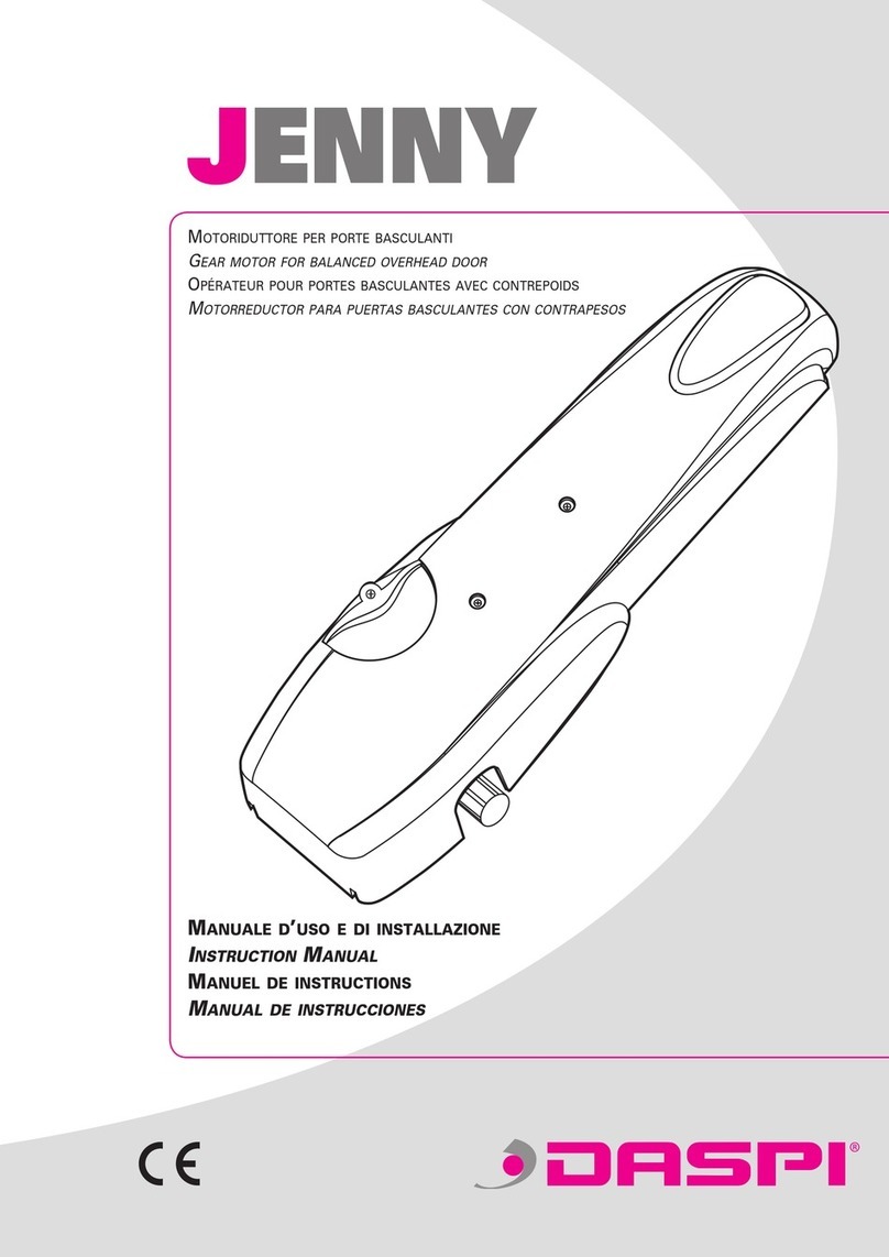
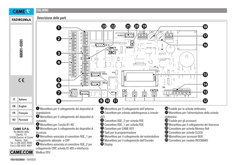
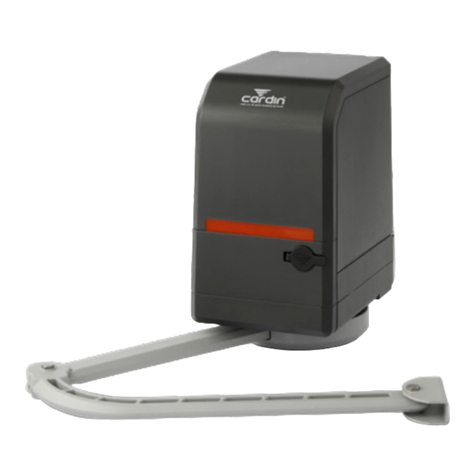
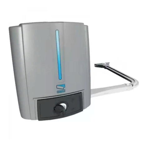
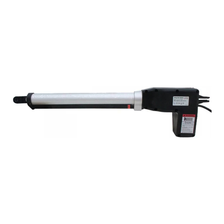
Daspi Hard Installer manual

MANUALE
ISTRUZIONI
E CATALOGO
RICAMBI
Motoriduttore per
cancellii.
Motorgetrieb
für Tore
INSTRUCTION
MANUAL
AND SPARE
PARTS
CATALOGUE
MANUEL
D'INSTRUCTIONS
ET CATALOGUE
DES PIECES
DETACHEES
ANLEITUNGS-
HANDBUCH UND
ERSATZTEIL-
KATALOG
97
I
GB FDNL
The gearmotor for
gates.
Motoreducteur pour
portails. Bochtarm aandrijving
voor draaihekken
MONTAGEHAND-
LEIDING EN
KATALOGUS VOOR
ONDERDELEN

2
SAFETY / SICUREZZA / SECURITE / SICHERHEIT / VEILIGHEID
Ci congratuliamo con voi per l'ottima scelta affidataci. Il vostro nuovo motoriduttore elettromeccanico è prodotto
sulla base di qualità ed affidabilità elevate; questo vi garantirà rendimento e sicurezza nel tempo.
Allegato al presente libretto troverete tutte le informazioni utili per il montaggio del vostro motoriduttore, e la
salvaguardia della vostra sicurezza.
Tutti i nostri prodotti sono costruiti in conformità alle normative vigenti.
è vietata ogni operazione di riparazione o regolazione dell'apparecchiatura alimentata se non
sono state prese tutte le precauzioni necessarie per evitare possibili incidenti (alimentazione elettrica disinserita,
blocco motore).
Tutti gli organi in movimento devono essere dotati delle opportune protezioni.
tutte le operazioni di riparazione devono essere eseguite da personale qualificato.
ogni modifica arbitraria apportata a questo prodotto, solleva la DASPI Automazioni Cancelli da
ogni responsabilità derivante da conseguenti danni o lesioni a cose, persone o animali.
Per un buon funzionamento dell'automazione il cancello da automatizzare dovrà rispondere alle seguenti
caratteristiche:
- buona equilibratura;
- buona scorrevolezza;
- in ogni caso l'apertura e la chiusura manuali devono potersi eseguire con facilità;
- ricordarsi che la motorizzazione è una facilitazione dell'uso del cancello e non risolve problemi dovuti a difetti e
deficienze di installazione o di mancata manutenzione del cancello stesso.
La prudenza è comunque insostituibile e non c'è regola migliore per prevenire gli incidenti.
:
:
:
Conservare scrupolosamente il presente manuale in un luogo idoneo e noto a tutti gli interessati.
ATTENZIONE
ATTENZIONE
ATTENZIONE
Our compliments for your excellent choice. Your new electromechanical gearmotor is produced according to the
strictest quality and reliability standards. This is your guarantee of life-long performance and safety.
This booklet will provide you with all the information you may need to assemble your gearmotor and safeguard
your safety.
All our items are made in conformity to the regulations in force.
: All repairs and adjustments on the equipment while the power is connected are strictly prohibited
unless all the necessary precautions are taken to avoid accidents (electrical supply cut-off, motor off).
All moving parts must be fitted with adequate guards.
: all repairs must be carried out by qualified specialists.
: DASPI Gate Automation shall not be held liable for any damage or injury whether to objects,
persons or animals caused by any unauthorised modifications made to this product.
For the automation to work efficiently, the gate being automated must meet the following characteristics:
- it must be well balanced
- it must swing freely
- the gate must be easily opened and closed by hand
- remember that this power driven accessory is merely designed to aid the use of the gate and will not overcome
problems due to a faulty or inadequate installation or poor maintenance.
However, there is no substitute for simple caution and there is nothing better than preventing accidents.
Treat this manual with due care and keep in a safe place, known to all interested parties.
IMPORTANT
IMPORTANT
IMPORTANT
Tous nos compliments pour votre excellent choix. Votre nouvel motoréducteur électromécanique est produit
selon des standards de qualité et de fiabilité très hauts: ceci vous assurera un service durable et en toute
sécurité.
Ce manuel vous fournit toutes les informations utiles pour le montage de votre motoréducteur et pour la
protection de votre sécurité.
Tous nos compliments ont été fabriqués conformément aux lois en vigueur.
: Toute opération de réparation ou de réglage de l’appareillage alimenté est interdite si on n’a pas
pris toutes les précautions nécessaires afin d’éviter de possibles accidents (alimentation électrique débranchée,
blocage du moteur).
Tous les organes en mouvement doivent être dotés des protections adéquates.
: toutes les opérations de réparation doivent être effectuées par du personnel qualifié.
: toute modification arbitraire apportée à ce produit relèvera DASPI Automazioni Cancelli de toute
responsabilité dérivée de dommages ou blessures aux choses, aux personnes ou à des animaux.
En tous les cas, la prudence est irremplaçable et il n’y a pas de meilleure règle pour éviter les accidents.
ATTENTION
ATTENTION
ATTENTION
I
GB
F
GATES AUTOMATION

3
Pour un bon fonctionnement de l’automation, le portail à automatiser devra satisfaire les caractéristiques
suivantes:
- il devra être bien équilibré
- il devra coulisser aisément
- l’ouverture et la fermeture manuelles devront pouvoir se faire facilement
- se rappeler que la motorisation n’est qu’un moyen pour faciliter l’utilisation du portail et ne résout pas les
problèmes dus à des défaillances et à des défauts d’installation ou d’entretien insuffisant du portail.
Wir gratulieren Ihnen zu Ihrer erstklassigen Wahl, mit der Sie uns das Vertrauen geschenkt haben. Unser neuer
elektromechanischer Antrieb wird in Hinsicht auf Qualität und große Zuverlässigkeit hergestellt. Dies wird Ihnen
mit der Zeit hohen Nutzen und Sicherheit garantieren.
In dieser Betriebsanweisung finden Sie alle nützlichen Informationen zur Montage Ihres Getriebemotors und der
Gewährleistung Ihrer Sicherheit.
Alle unsere Produkte werden nach den jetztigen Normen hergestellt.
: Jede Reparatur oder Einstellung am an die Stromversorgung angeschlossenen Gerät ist verboten,
wenn vorher nicht alle notwendigen Vorsichtsmaßnahmen zur Unfallverhütung getroffen worden sind
(elektrische Stromversorgung abgeschaltet, Motorsperre).
Alle beweglichen Elemente müssen mit den geeigneten Schutzvorrichtungen ausgestattet sein.
: Alle Reparaturtätigkeiten müssen von Fachpersonal durchgeführt werden.
: Jede willkürliche Veränderung, die an diesem Produkt vorgenommen worden ist, enthebt die DASPI
Automazioni Cancelli jedweder Verantwortung für Folgeschäden oder Verletzungen von Sachen, Personen
oder Tieren.
Für einen störungsfreien Betrieb der Automation muß der angetriebene Flügel folgende Eigenschaften
aufweisen:
- Gute Ausbalancierung
- Gute Gleitfähigkeit
- Die manuelle Öffnung und Schließung müssen sich auf jeden Fall leicht durchführen lassen.
- Bitte vergegenwärtigen, daß die Motorisierung eine Erleichterung bei der Verwendung des Flügels darstellt und
keine Probleme löst, die auf Installationsdefekte und -mängel oder nicht durchgeführte Wartungen dieses
Flügels zurückzuführen sind.
Die Vorsicht jedoch ist unersetzbar und die wirksamste Maßnahme zur Verhinderung von Unfällen.
Dieses Handbuch bitte sorgfältig an einem geeigneten und allen Beteiligten bekannten Ort
aufbewahren.
ACHTUNG
ACHTUNG
ACHTUNG
D
NL
GATES AUTOMATION
Gefeliciteerd met Uw excellente keuze. Uw nieuwe electro-mechanische hekaandrijving is ontwikkeld en
gefabriceerd volgens de strengste kwaliteitsnormen. Hierdoor heeft deze aandrijving een hoge
betrouwbaarheid en een lange levensduur.
In deze handleiding vindt U alle nuttige informatie voor de montage en de veiligheid van deze aandrijving.
Al onze produkten worden conform de wettelijke richtlijnen geproduceerd.
: Alle herstellingen of regelingen aan een op de netspanning aangesloten apparatuur zijn strikt
verboden, indien niet alle benodigde maatregelingen zijn getroffen om elektrocutie te voorkomen (netspanning
onderbreken, motor afkoppelen).
Alle bewegende onderdelen moeten met daarvoor bestemd gereedschap geblokkeerd worden.
: Alle herstellingen mogen uitsluitend door een gekwalificeerd vakman uitgevoerd worden.
:Noch DASPI Gate Automation, noch SECULUX bvba kunnen verantwoordelijk gesteld worden voor
schade of verwondingen, ten gevolge van door derden aangebrachte veranderingen aan het originele produkt.
Gelieve volgende punten in acht te nemen om een storingvrije aandrijving van Uw hekken te garanderen :
- het hek moet gebalanceerd zijn
- het hek moet vrij kunnen draaien
- het hek moet gemakkelijk manueel te openen/sluiten zijn
- onthou dat deze automatisatie ontworpen is om comfortabel het hek te openen en te sluiten. Ze is niet geschikt
voor slecht onderhouden en moeilijk te openen hekkens.
Toch, voorzichtigheid geboden .
Bewaar deze handleiding zorgvuldig op een veilige en vaste plaats zodat alle belanghebbenden altijd
deze handleiding kunnen raadplegen .
om ongevallen te voorkomen blijft
OPGELET
OPGELET
OPGELET

TECHNICAL DATA / DATI TECNICI / CARACTERISTIQUES TECHNIQUES / TECHNISCHE
DATEN / TECHNISCHE SPECIFICATIES
4
PRELIMINARY CHECKS / VERIFICHE E PRELIMINARI / VERIFICATIONS PRELIMINAIRES /
PRÜFUNGEN UND VORBEREITENDE ARBEITEN / VOORBEREIDEND WERK
1 - Leggere con
massima attenzione
quanto riportato nel
manuale.
2 - Assicurarsi che la
struttura del cancello
sia solida e che
durante il suo
movimento non
abbia punti d'attrito.
3 - Assicurarsi che il
cancello sia
bilanciato bene,
anche dopo aver
montato il
motoriduttore.
4 - Verificare che
l'impianto elettrico
sia conforme alle
caratteristiche
richieste dal
motoriduttore e
indicate in Tabella 1.
1 - Den Inhalt dieses
Handbuches
aufmerksam lesen.
2 - Sicherstellen,
daß das
Flügelgerüst solide
ist und während
seiner Bewegung
keine
Reibungsstellen hat.
3 - Sicherstellen,
daß der Flügel auch
nach der Montage
des Antriebes gut
ausbalanciert ist.
4 - Überprüfen, ob
die elektrische
Anlage die für den
Antrieb
erforderlichen und in
Tabelle 1
aufgeführten
Merkmale aufweist.
1 - Carefully read all
the instructions
given in this manual.
2 - Make sure that
the gate has a solid
frame and that there
are no stiff points in
its movement.
3 - Make sure that
the leaf is well
balanced even after
the gearmotor is
mounted.
4 - Check that the
electrical plant
complies with the
characteristics
required by the
gearmotorr, given in
Table 1.
1 - Lire attentivement
les instructions de ce
manuel.
2 - S’assurer que la
structure du vantail
est solide et que
pendant son
mouvement elle n’a
pas des points de
frottement.
3 - S’assurer que le
vantail est bien
équilibré, même
après le montage de
le motoréducteur.
4 - Vérifier que
l’installation
électrique est
conforme aux
caractéristiques de
le motoréducteur
indiquées dans le
Tableau 1.
LUBRICATION / LUBRIFICAZIONE / LUBRIFICATION / SCHMIERUNG / SMERING
I motoriduttori HARD
vengono forniti con
lubrificazione
permanente.
DIMENSIONS / DIMENSIONI / DIMENSIONS / RAUMBEDARF / AFMETINGEN
HARD gearmotors
are supplied
lubricated for life.
Les motoréducteurs
HARD sont fournis
avec lubrification
permanente.
Die Antriebe HARD
werden mit
Permanentschmierung
geliefert.
Figure / Figura / Figure / Abb. / Figuur 1
Table / Tabella / Tableau / Tabelle / Tabla 1
I
GB F D NL
I
GB F D NL
I
GB F D NL
Max gate length Lunghezza max anta Longueur maxi
du portail
Maximale
Flügellänge
Maximale
Vleugelbreedte
2.5 m
Rated power Potenza Puissance Leistung Vermogen 170 W
Power supply Alimentazione Alimentation Speisung Aansluitspanning 220/230 V
Absorbed power Assorbimento Puissance Absorbée Aufnahme Stroomverbruik 1,3 A
Operating
temperature
Temperatura di
esercizio
Température
d’emploi
Betriebstemperatur Omgevings-
Temperatuur
-25°C
+70°C
Noise level Rumorosità Niveau de bruit Lautstärke Geluidsniveau 46 db
Gearmotor weight Peso motoriduttore Poids du
motoréducteur
Gewicht des
Getriebemotors
Gewicht van de
Motorreductor
12 Kg
Dimensions Dimensioni Dimensions Abmessungen Afmetingen 300x145x180
Cycles per hour Cicli per ora Cycles/heure Arbeitszyklen pro
Stunde
Bewegingen per uur 40
GATES AUTOMATION
300
180
145
1 - Lees eerst
aandachtig deze
handleiding.
2 - Zorg ervoor dat
het hek gemakkelijk
met de hand te
bedienen is. En
controleer of het hek
wel stevig genoeg is
voor de kracht van
de motor.
3 - Zorg ervoor dat
het hek in evenwicht
is, ook na de
montage van de
aandrijving.
4 - Kontroleer de
elektrische
bedrading, deze
moet conform de
voorschriften in tabel
1 zijn.
De HARD
aandrijving hoeft
nooit gesmeerd.

LAYOUT / QUADRO D'INSIEME / SCHEMA DE MONTAGE / ÜBERSICHTSZEICHNUNG /
INSTALLATIE SCHEMA
5
A - Linea 230 V
1- Colonnina
fotocellula
2- Fotocellula
3- Antenna
4- Lampeggiatore
5- Quadro di
comando (centralina
elettronica)
6- Motoriduttore
HARD
7- Selettore a chiave
o tastiera digitale
8- Cartello di
sicurezza
A - 230 V line
1 - Photocell column
2 - Photocell
3 - Antenna
4 - Flasher
5 - Electronic control
unit
6 - HARD gearmotor
7 - Key switch or
keypad
8 - Security
A - Ligne à 230 V
1 - Colonne pour
cellule
photoélectrique
2 - Cellule
photoélectrique
3 - Antenne
4 - Clignoteur
5 - Tableau de
commande (centrale
électronique)
6 - Motoreducteur
HARD
7 - Sélecteur à clé
ou clavier numérique
8 - Ecriteau de
securitè
A - Leitung 230 V
1 - Säule für
Photozelle
2 - Photozelle
3 - Antenne
4 - Blinklicht
5 - Steuertafel
(Elektronische
Steuerzentrale)
6 - HARD
Getriebemotors
7 - Schlüsselschalter
oder Digitaltastatur
8 - Sicherheitsschild
Figure / Figura / Figure / Abb. / Figuur 2
I
GB F D NL
GATES AUTOMATION
RG58
3x1.5
2x1
2x1 4x1
3x1
4x1
4x1.5
4x1.5
2x1.5
A - Voeding 230 V
1 - Paal voor fotocel
2 - Fotocellen
3 - Antennne
4 - Knipperlamp
5 - Electronische
stuurkast
6 - Aandrijving
HARD
7 - Sleutelschakelaar
of kodeklavier
8 - Waarschuwings-
bord

UNPACKING AND INSTALLATION / DISIMBALLO ED INSTALLAZIONE / DEBALLAGE ET
INSTALLATION / AUSPACKEN UND INSTALLATION / UITPAKKEN EN INSTALLATIE
6
I
GB
Per una corretta messa in opera del motoriduttore HARD, agire come segue:
1 - Aprire l'imballo ed estrarre il motoriduttore HARD, avendo cura di verificare che lo stesso non abbia subito danni
durante il trasporto.
2 - Assicurarsi che l'anta sia perfettamente orizzontale.
3 - Verificare che l'operatore sia completo di staffe di fissaggio e di leve.
4 - Posizionare la staffa di ancoraggio nel pilastro, rispettando le quote indicate in figura 4-5, per aperture da 90° a
massimo 125°, utilizzando viti o tappi ad espansione adeguati al pilastro.
N.B.: Ogni piastra è sia destra che sinistra (eventualmente si inverta il motoriduttore).
5 - Fissare il motoriduttore alla piastra con le due viti, orientando sempre il perno d'uscita verso l'anta da motorizzare
(figura 5).
6 - Assemblare le leve come indicato in figura 6.
7 - Infilare la leva e boccola nella parte dentata del motoriduttore (albero uscita), avendo cura di fissare il tutto (sia di lato
che sotto) (figura 7).
8 - Sbloccare il motoriduttore azionando la chiave di sblocco "CH", come mostrato in figura 8.
9 - Posizionare la leva rispettando la quota indicata in figura 9.
10 - Fissare l'angolare all'anta con viti o mediante saldatura.
11 - Mantenendo il motoriduttore sbloccato, verificare il corretto movimento della leva e dell'anta.
12 - Ripetere la stessa operazione per l'altra anta.
1 - Dopo aver tolto l'alimentazione elettrica, togliere le viti laterali e sollevare il carter, come mostrato in figura 10.
2 - Identificare il finecorsa "C" di chiusura (inferiore) e il finecorsa "A" di apertura (superiore), indicati in figura 11.
3 - Con l'anta del cancello chiusa, ruotare la camma inferiore "Cc", indicata in figura 12, fino a sentire e vedere lo scatto, e
bloccarla fissando il grano.
4 - Con l'anta del cancello aperta, ruotare la camma superiore "Ca", indicata in figura 12, fino a sentire e vedere lo scatto,
e bloccarla fissando il grano.
Regolazione finecorsa (kit opzionale)
For a right function of the gearmotor HARD proceed as follows:
1 - Open the packing and slide the gearmotor HARD, taking care of testing that the same one has not been damaged
during the transport.
2 - Make sure that the leaf is perfectly level.
3 - Check that the operator is complete of bracket of mounting and of the lever.
4 - Put the bracket of anchorage on the pillar, respecting the quotes indicated on the picture 3-4., for openings from 90° to
a maximum of 125°, by using two bolts or stoppers for expansion suitable for the pillar.
N.B. : Each plate is both on the right and on the left (eventually you can invert the gearmotor).
5 - Mount the gearmotor on the plate with two bolts, leading always the hinge pin of exit towards the leaf to motorize
(picture 5).
6 - Assemble the lever as indicated on the picture 6.
7 - Introduce the lever and the bush on the cog side of the gearmotor (shaft outer), taking care of mounting everything
(both on the side and under) (picture 7).
8 - Release the gearmotor by switching on the key of releasing "CH", as shown in picture 8.
9 - Put the lever respecting the quote indicated on the picture 9.
10 - Mount the angular on the leaf with bolts or with welding.
11 - Keep the gearmotor unblocked, test the right movement of the lever and of the leaf.
12 - Repeat the same operation for the other leaf.
1 - Afterturning off the eletric power, take off the lateral bolts and pull the carter, as it is shown in figure 10.
2 - Identify the end race "C" of closing (inferior) and the end race "A" of opening (superior), as shown in figure 11.
3 - With the closed leaf of the gate, turn the inferior cam "Cc" , shown in figure 12, until you hear and see the release, and
block it by fixing the grane.
4 - With the opened leaf of the gate, turn the superior cam "Ca", shown in figure 12, until to hear and to see the release,
and block it by fixing the grane.
5 - Make the necessary connections, as shown in figure 13.
6 - After mounting and fixing the carter,turn on the eletric power.
If the control unit requires the stroke time adjustement, to this one must be assigned a value over about three seconds to
the introduction of the travel stops of the gearmotor.
Regulation travel stop (optional kit)
GATES AUTOMATION

7
F
D
5 - Effettuare i collegamenti necessari, come mostrato in figura 13.
6 - Dopo aver montato e fissato il carter, ripristinare l'alimentazione elettrica.
Se la centrale di comando prevede la regolazione del tempo di lavoro, a questo deve essere assegnato un valore
superiore di circa 3 secondi al tempo di intervento dei finecorsa del motoriduttore.
Pour une mise en ouvre correcte du moto-rèducteur HARD, procèder comme suit:
1 - Ouvrir l' emballage et sortir le moto-rèducteur HARD, en vèrifiant tout d' abord qu' il n'a pas subi de dommages
pendant le transport.
2 - S' assurer que le vantail soit parfaitement horizontal.
3 - Vèrifier que l' operateur soit complèt de pattes de fixage et des leviers.
4 - Positionner la patte de ancrage dans le pilastre, en respectant les quotes indiquèes dans la figure 3-4, pour ouvrages
de 90° jusqu'à max 125°,en utilizant vises ou bouchons àexpansion indiques pour le pilastre.
N.B. Chaque plaque est soit droite soit gauche (eventualement on inverte le moto-rèducteur).
5 - Fixer le moto-rèducteur sûr la plaque avec deux vises, en orientand toujours le goujou de sortie vers le vantail que doit
etre motorizè (figure 5).
6 - Assembler les leviers comme indiqué dans la figure 6.
7 - Introduir le levier et la bague dans la parte cannelée du moto-réducteur (arbre de sortie), en vérifiant de fixer le tout
(soit de coté soit sout)(figure 7).
8 - Débloquer le moto-réducteur en actinnand la clée de déblocage "CH" comme montré dans la figure 8.
9 - Posittioner la levier en rèspectant la quote indiquée dans la figure 9.
10 - Fixer le cornière du vantail avec vises ou avec soudre.
11 - En maintenand le moto-rèducteur dèbloquè, vèrifier le correcte mouvement de le levier et du vantail.
12 - Rèpeter la même operation pour l 'autre vantail.
1 - Après avoir fermé l' alimentation èlètrique , sortir les vises latérales et soulever le carter , comme montré en figure 10.
2 - Identifier la fin de course "C" de fermeture (inferior) et la fin de course "A" de ouverture (superior), indiqués en figure 11.
3 - Avec le vantail fermée de la grille, tourner la camme inferiore "Cc", indiquée en figure 12, jusqu' à sentir et voir le
déclenchement et la bloquer en fixant le graine.
4 - Avec le vantail de la grille ouverte, tourner la camme superiorre "Ca", indiquée en figure 12, jusqu' à sentir et voir le
dèclenchement, et la bloquer en fixant le graine.
5 - Efectuer les jonctions necessaires, comme montré en figure 13.
6 - Après avoir monté et fixé le carter, rètablir l' alimentation èlétrique.
Si la centrale du command prevoit le règlage du temps de travail, à cèlà doit être assegnè un valoir superior de a peu prés
trois secondes au temps de introduction des fins de course de moto-réducteur.
Regulation de la fin de course (kit optional)
Für eine richtige Inbetriebsetzung des Getriebemotors HARD, wie folgt vorgehen:
1 - Die Verpackung öffnen und das Getriebemotor HARD herausziehen, hierbei sorgfältig prüfen, ob er keine
Transportschäden erlitten hat.
2 - Sich vergewissern, daß der Flügel vollkommen waagerecht ist.
3 - Sich vergewissern, daß der Reparateur vollkommen von Bügel und von Aushebung ist.
4 - Den Bügel von Verankerung in die Pfeilen einstellen, die auf der Figure 3-4 gezeigten Quoten beachten, für öffnungen
von 90° bis zum Maximum 125° und geeignete Schrauben oder Ausdehnungsschrauben für den Pfeiler brauchen.
N.B. Jede Platte ist sowohl rechts als auch links ( sonst kann man den Getriebemotor verwechseln ).
5 - Den Getriebemotor an die Platte mit zwei Schrauben befestigen, das Ausgangsbolzen zum Motorisierungsflügel
immer orientieren (Figure 5).
6 - Die Aushebung zusammenfügen, wie es in der Figure 6 gezeigt wird.
7 - Die Aushebung und die Büchse in die gezackte Seite des Getriebemotors einziehen (Ausgangswelle); sich
vergewissern, daß alles befestigt wird.(sowohl an der Seite als auch untern) (Figure 7).
8 - Durch den Notfreigabesschüssel "CH" den Getriebemotor freigeben, wie es in der Figure 8 gezeigt wird.
9 - Die Aushebung einstellen und die auf der Figure 9 gezeigte Quote beachten.
10 - Den Winkeleisen an den Flügeln entweder mit Schrauben oder mit Schweissung befestigen.
11 - Der Getriebemotor soll entblockt bleiben; sich vergewissern, daß die Bewegung der Aushebung und des Flügels
richtig ist.
12 - Die selbe Operation für die anderen Flügel widerholen.
1 - Nachdem man den elektrischen Strom geschlossen hat, ziehen die seitlichen Schrauben heraus und den Carter
heben, wie es in Figure 10 gezeigt wird.
Einstellung des laufsendes (optionales kit)
GATES AUTOMATION

8
NL
Figure / Figura / Figure / Abb. / Figuur 3
GATES AUTOMATION
2 - Das Laufsende "C" von Geschlossenheit (unteres) und das Laufsende "A" von Öffnung (obenes) identifizieren, die in
Figure 11 gezeigt werden.
3 - Mit dem geschlossenen Flügel der Gittertür, den unteren Nocken "Cc" drehen, wie sie in Figure 12 gezeigt wird, bis
das Hören und das Sehen des Schnappens, und sie durch die Befestigung des Stiftes bloquieren.
4 - Mit dem geöffneten Flügel der Gittertür, den obenen Nocken "Ca" drehen, wie sie in Figure 12 gezeigt wird, bis das
Hören und das Sehen des Schnappens, und sie durch die Befestigung des Stiftes bloquieren.
5 - Die nötigen Verbindungen tun, wie es in figure 13 gezeigt wird.
6 - Nachdem man den Carter aufgestellt und befestigt hat, stellen den elektrischen Strom wiederher.
Wenn die Steuerzentrale die Einstellung der Arbeitszeit voraussieht, ein Wert über drei Sekunden an der Zeit des
Dazwischentretens des Laufsendes des Getriebsmotors gegeben sein soll.
110
90°
300
max
125°
170
Voor een probleemloze installatie van de HARD aandrijving, volg strikt de volgende procedure:
1 - Open de verpakking en controleer de aandrijving op eventuele transportschade.
2 - Verzeker U dat het hek perfect horizontaal opgehangen is.
3 - Controleer of de motor voorzien is van een muurbevestiging en een bochtarm.
4 - Monteer - best met - de muurbevestiging tegen de paal rekening houdend met de maten
weergegeven in figuur 4.
5 - Monteer de motor d.m.v. de twee bijgeleverde bouten op de muurbevestiging, de aandrijfas steeds aan de onderkant.
Zie figuur 5.
6 - Assembleer de bochtarm zoals weergegeven in figuur 6.
7 - Schuif de getande bus van de bochtarm over de aandrijfas van de motor en borg deze zowel langs onder als
zijdelings . Zie figuur 7.
8 - Ontgrendel de motor d.m.v. de meegeleverde inbussleutel “CH” in de positie “OPEN” te draaien (zie figuur 8).
9 - Strek nu de bochtarm zoals weergegeven in figuur 9.
10 -Bevestig nu het uiteinde van de bochtarm d.m.v. schroeven of lassen tegen het hek .
11 - Laat de motor ontgrendeld, test de beweging van de bochtarm en het hek.
12 -Herhaal bovenvermelde punten voor de andere vleugel van het hek.
Afregelen van de eindeloop schakelaars (optionele kit).
1 - Verwijder de kunststof behuizing na dat U eerst de netspanning heeft onderbroken (zie figuur 10).
2 - Identificeer de eindeloop schakelaar “C” (onderste) voor sluiten en “A” (bovenste) voor openen (zie figuur 11).
3 - Sluit het hek, draai de onderste nok “Cc” tot U de eindeloop schakelaar “C” hoort en ziet sluiten. Borg deze nok nu
door het vastdraaien van de inbusbout. (zie figuur 12).
4 - Open het hek, draai de bovenste nok “Ca” tot U de eindeloop schakelaar “A” hoort en ziet sluiten. Borg deze nok nu
door het vastdraaien van de inbusbout. (zie figuur 12).
5 - Sluit de elektrische bedrading nu aan zoals afgebeeld in figuur 13.
6 - Zet de netspanning pas aan na het terug monteren van de kunststof behuizing.
Indien deze motor aangesloten wordt op een elektronische stuurkast met instelbare looptijd, dan moet deze tijd
3 seconden langer zijn dan de motor effectief nodig heeft voor het openen of sluiten van het hek.
chemische ankers

9
Figure / Figura / Figure / Abb. / Figuur 4
Figure / Figura / Figure / Abb. / Figuur 5
Figure / Figura / Figure / Abb. / Figuur 6 Figure / Figura / Figure / Abb. / Figuur 7
GATES AUTOMATION
A
B
B
Apertura 90°
Ouverture à 90°
90° -Öffnung
Apertura 90°
320 160
125° opening
Apertura 125°
Ouverture à 125°
125° -Öffnung
Apertura 125°
320 220
90° opening
A
SX DX

10
Figure / Figura / Figure / Abb. / Figuur 8 Figure / Figura / Figure / Abb. / Figuur 9
Figure / Figura / Figure / Abb. / Figuur 10 Figure / Figura / Figure / Abb. / Figuur 11
Figure / Figura / Figure / Abb. / Figuur 12
A: End race of opening / finecorsa di apertura / fin de course de ouverture / Laufsende von Öffnung / Eindeloop schakelaar open.
C: End race of closing / finecorsa di chiusura / fin de course de fermeture / Laufsende von Geschlossenheit / Eindeloop
schakelaar sluiten.
1: Close / chiude / ferme / schließt / sluiten.
2: Comun / comune / comune / gemeinsam / gemeenschappelijk.
3: Open / apre / ouvre / öffnet / openen.
Figure / Figura / Figure / Abb. / Figuur 13
GATES AUTOMATION
770
A
C
Ca
Cc
2
** 3
1
A*
C*
CH

ANTI-PANIC PROCEDURES / MANOVRE DI EMERGENZA / MANOEUVRES
D'URGENCE / VORGÄNGE IM NOTFALL / NOODONTGRENDELING
11
In the case that it is
necessary to make
work manually the
leaf, do as follows :
- turn off the
electrical system
- take out the cap in
the middle of the
carter, "figure 14"
- put inside the key
"5" provided, paying
attention that it goes
inside the right
screw
- make it turn
clockwise /
anticlockwise, so
that the transmission
is free."figure 15"
- in order to reinsert
the transmission, it is
sufficient to make
the usual key "5"
work
- make it turn
clockwise /
anticlockwise,
making sure
manually that the
leaf is blocked
"figure 15"
- put inside the cap
and retsore the
power, paying
always attention that
there are no people
in the place where
the leaf is working.
Nel caso in cui sia
necessario agire
manualmente
sull'anta, agire come
segue:
- togliere l'alimenta-
zione elettrica
- togliere il tappo
dalla parte centrale
del carter,"figura 14"
- inserire la chiave
"5" in dotazione,
prestando attenzione
che entri nella vite
corretta
- girare la vite in
senso orario/anti-
orario, per liberare la
trasmissione, "figura
15"
- per rinserire la
trasmissione, è
sufficiente agire
nuovamente sulla
chiave "5"
- farla girare in senso
orario/antiorario,
verificando
manualmente che
l'anta sia bloccata
"figura 15"
- rinserire il tappo e
ripristinare
l'alimentazione
elettrica, prestando
sempre attenzione
che non vi siano
persone nell'area in
cui l'anta si sta
muovendo.
Dns le cas qu' on
doit necessairement
faire actinner
manuellement le
vantail, procèder
comme suit :
- bloquer la
èlectricité
- sortir le bouchon
au centre du carter,
"figure 14"
- introduir la clè "5"
fornie, en faisant
attention que la clè
entre en la correcte
vis.
- tourner la vis dans
le sens correcte
/contraire d' une
montre, à fin de faire
actinner la
transmission. "figure
15"
- pour reinsereir la
transmission, il est
suffisant de
actionner la meme
clè "5" dans le sense
correcte/contraire d'
une montre, en s'
assurant
manuellement que le
vantail soit bloquè
"figure 15"
- introduir le bouchon
et rétablisser le
courant, en faisant
attention que il n' y a
pas de gens où le
vantail est en train de
travailler.
Wenn es nötig ist,
manuell den Flügel zu
bedienen, wie folgt
vorgehen :
- machen den Stron zu
- den Stopfen
herausziehen, der am
Mittel des Carters ist,
"Figure 14"
- den Schlüssel "5", in
der Standardsausr-
üstung enthalten,
einziehen und sich
vergewissern, daß er in
die richtige Schraube
eintritt.
- den Schlüssel in den
/ gegen den
Uhrzeigersinn drehen,
so daß die
Transmission frei ist.
"Figure 15"
- um die Transmission
wieder einzuziehen, ist
es notwendig, den
selben Schlüssel "5" in
den/gegen den
Uhrzeigersinn drehen
und manuell sich
vergewissern, daß der
Fl gel befestigt
ist."Figure 15"
- den Stopfen
einziehen und den
Storm vorhanden.
-sichimmer
vergewissern, daß es
keine Leute neben
dem bewegenden
Flügel gibt.
ü
Figure / Figura / Figure / Abb. / Figuur 15
I
GB FDNL
Figure / Figura / Figure / Abb. / Figuur 14
GATES AUTOMATION
5
Indien het hek
manueel moet
kunnen bewegen,
volg volgende
procedure:
- zet de elektriciteit
af
- verwijder het
zwarte dopje om het
sleutelgat vrij te
maken.
- Plaats de
ontkoppelingssleutel
“5” via het sleutelgat
in het
ontgrendelingsme-
chanisme.
- Draai in
wijzerzin/tegenwijzer
zin om de motor te
ontgrendelen (zie
figuur 15). Haal de
sleutel terug uit het
sleutelgat en bedien
het hek nu manueel.
- Herhaal
bovenstaande
handeling in
omgekeerde
volgorde om de
motor terug te
vergrendelen..
- de elektriciteit terug
inschakelen en
vergewis U altijd dat
er zich geen
personen in het
draaiveld van het
hek bevinden.

12
USING THE AUTOMATION / USO DELL'AUTOMAZIONE / UTILISATION DE L'AUTOMATION /
VERWENDUNG DER AUTOMATION / BEDIENING
Il motoriduttore HARD è stato progettato e costruito per l'apertura di cancelli di ante di dimensioni
massime di 2,5 metri.
La DASPI non si assume nessuna responsabilità per un uso diverso da quello previsto dal motoriduttore
HARD.
Poichè l'automazione può essere comandata a distanza e non a vista mediante pulsante o telecomando, è
indispensabile controllare frequentemente la perfetta efficenza di tutti i dispositivi di sicurezza.
Si consiglia di controllare periodicamente (ogni sei mesi) la regolazione della frizione elettronica in dotazione.
Nel caso vi fosse l'esigenza di tarare tale protezione, consultare il paragrafo "Regolazione frizione elettronica"
nel libretto d'istruzioni della centralina elettronica.
The HARD gearmotor has beeen planned and carried out to open gates with a maximum lea length of
2,5 metres.
DASPI declines all responsibility for any use of the HARD gearmotor other than its specific purpose.
Since the automation can be operated at a distance and out of the sight of the operator, by means of a button or
remote control, it is essential that the efficiency of all safety devices is controlled frequently.
We strongly recommend periodical controls (i.e. every six months) of its electronic clutch adjustment.
If this protection should require calibration, consult the section "Adjustment of the electronic clutch" in the
electronic control unit’s instruction booklet.
El motoreducteur HARD a été projeté et réalisé pour ouvrir des vantaux avec des dimensions maximales
jusqu’à 2,5 mètres.
DASPI n’assume aucune responsabilité en cas d’emploi différent de celui prévu de le motoréducteur
HARD.
Puisque l’automation peut être commandée à distance et hors de vue au moyen d’une touche ou d’une
télécommande, il est indispensable de contrôler souvent le fonctionnement parfait de tous les dispositifs de
sécurité.
Il est conseillé de contrôler périodiquement (tous les six mois) le réglage de l’embrayage électronique fourni.
Si un étalonnage de la protection était nécessaire, consulter le paragraphe "Réglage de l’embrayage
électronique" dans le manuel d’instructions de la centrale électronique.
Der Getriebmotor HARD ist für die Öffnung von Flügeln mit Abmessungen von maximal 2,5 Metern
entwickelt und gebaut worden.
Die DASPI übernimmt keinerlei Verantwortung für eine Art der Verwendung, die nicht für den Antrieb
HARD vorgesehen ist.
Weil die Automation auf Entfernung ohne Sichtkontakt mittels Knöpfen oder Fernsteuerung gesteuert werden
kann, ist die häufige Kontrolle aller Sicherheitsvorrichtungen unentbehrlich.
Es wird empfohlen, in bestimmten Zeitabständen (alle sechs Monate) die Einstellung der in der
Standardausrüstung enthaltenen elektronischen Kupplung zu kontrollieren.
Sollte die Tarierung dieser Schutzvorrichtung notwendig sein, bitte im Abschnitt "Einstellung der elektronischen
Kupplung" in der Gebrauchsanweisung für die elektronische Steuerungszentrale nachschauen.
I
GB
F
D
NL
GATES AUTOMATION
De HARD aandrijving is ontworpen voor draaihekken met open vleugels van max. 2,5 meter.
Noch DASPI of SECULUX zijn verantwoordelijk voor schade of verwondingen indien deze aandrijving
gebruikt wordt voor andere toepassingen..
Daar het hekken d.m.v een drukknop of afstandsbediening kan geopend en gesloten worden buiten het zichtveld
van de gebruiker, is het essentieel dat alle veiligheidsvoorzieningen gecontroleerd en getest
worden.
Wij raden sterk aan om op regelmatige tijdstippen (vb. elke zes maanden) de werking van de elektronische
krachtregeling te controleren en indien nodig bij te stellen. Raadpleeg de handleiding van de electronische
stuurkast voor de juiste afstelling van de krachtregeling.
regelmatig

MAINTENANCE / MANUTENZIONE / ENTRETIEN / WARTUNG / ONDERHOUD
DISPOSAL / DEMOLIZIONE / DEMOLITION / VERSCHROTTUNG / AFBRAAK
13
L'eliminazione dei
materiali va fatta
rispettando le norme
vigenti.
E' opportuno, in
caso di recupero
materiali, separarli
per tipologia (rame,
alluminio, plastica,
parti elettriche etc.).
Il motoriduttore
HARD viene fornito
con lubrificazione
permanente a
grasso e quindi non
necessita di
manutenzioni.
Per una corretta
manutenzione
dell'impianto dove il
motoriduttore HARD
è inserito, procedere
come segue:
- pulire
periodicamente le
ottiche delle
fotocellule;
- frizione elettronica
(vedere paragrafo
installazione centrale
elettronica).
PERICOLO: per
qualsiasi tipo di
manutenzione,
togliere
l'alimentazione.
The HARD
gearmotor is
greased for life and
therefore does not
require
maintenance.
For a correct
maintenance of the
plant involving the
HARD gearmotor,
proceed as follows:
- periodically clean
the photocells
- service the
electronic clutch
(see section
installation of
electronic control
unit).
DANGER: always
cut-off the power
supply when
carrying out any
type of
maintenance.
Le motoreductéur
HARD est fourni
avec lubrification
permanente à
graisse et ne
nécessite donc
d’aucun entretien.
Pour en entretien
correct de
l’installation où le
motoreductéur
HARD est monté,
procéder comme
suit:
- nettoyer
périodiquement les
optiques des cellules
photoélectriques;
- embrayage
électronique (voir
paragraphe
"Installation de la
centrale
DANGER: pour
n’importe quel
entretien, couper
l’alimentation.
Der Antrieb HARD
wird mit
permanenter
Fettschmierung
geliefert und benötigt
diesbezüglich keine
Wartung.
Für eine korrekte
Wartung der Anlage,
in welche der Antrieb
HARD eingefügt
wurde, wie folgt
vorgehen:
- In bestimmten
Zeitabständen die
Optik der Fotozellen
reinigen.
- Elektronische
Kupplung (siehe
Abschnitt Installation
der elektronischen
Steuerzentrale).
GEFAHR: Bei jeder
Art von Wartung
die
Stromversorgung
unterbrechen.
All materials must be
disposed of
according to current
regulations.
To facilitate recycling
of each material,
they should be
divided by type (e.g.
copper, aluminium,
plastic, electrical
parts, etc.)
Les matériaux
doivent être éliminés
selon les normes en
vigueur.
En cas de
récupération de
matériaux, il est
souhaitable de les
séparer par type
(cuivre, aluminium,
plastique, parties
électriques etc.).
Die Entsorgung der
Materialien muß
unter Beachtung der
geltenden
Vorschriften
erfolgen.
Sollen Materialien
wiederverwertet
werden, ist eine
Trennung nach
Stoffarten
angebracht (Kupfer,
Aluminium, Plastik,
Elektrische Teile
usw.).
I
GB FDNL
I
GB
FDNL
GATES AUTOMATION
De HARD
aandrijving is
gesmeerd voor zijn
hele levensduur, en
is hierdoor
onderhoudsvrij.
Om een correct
onderhoud uit te
voeren op de plaats
waar een HARD
aandrijving is
geïnstalleerd, volg
volgende procedure:
- Regelmatig de
fotocellen reinigen.
- De elektronische
krachtregeling regel-
matig controleren
(raadpleeg de
handleiding van de
elektronische
stuurkast).
GEVAAR: Voor alle
montage- en
onderhoudswerk-
zaamheden de
stroomvoorziening
onderbreken .
Alle onderdelen
moeten volgens de
in ons land geldende
wetgeving inzake
recyclage ingeleverd
worden.
Om het recycleren te
vergemakkelijken
moeten alle
onderdelen van het
zelfde materiaalsoort
gesorteerd worden
(Koper, aluminium,
kunststof, elektrische
onderdelen, enz.).

14
DISMANTLING / SMANTELLAMENTO / DEMONTAGE / ABBAU / DEMONTAGE
Per spostare
l'automazione in
altra sede bisogna:
- togliere
l'alimentazione e
scollegare l'impianto
elettrico;
- smontare il quadro
di comando e tutti i
componenti
dell'istallazione.
Nel caso in cui
alcuni componenti
risultassero
danneggiati o
impossibilitati ad
essere rimossi,
provvedere alla loro
sostituzione.
To relocate the
automation proceed
as follows:
- cut-off the power
supply and
disconnect the
electrical plant;
- dismantle the
control box and all
the other
components in the
installation.
If any components
are found damaged
or cannot be
removed, they
should be replaced.
Um die Automation
an einer anderen
Stelle anzubringen,
muß man:
- Den Strom
abschalten und die
elektrische Anlage
abbauen;
- Die Steuertafel und
alle
Installationskompon
enten demontieren.
Sollten einige
Bestandteile
beschädigt sein oder
nicht entfernt werden
können, müssen sie
ersetzt werden.
Pour déplacer
l’automation ailleurs,
il faut:
- couper
l’alimentation et
débrancher
l’installation
électrique;
- démonter le
tableau de
commande et tous
les composants de
l’installation.
Au cas où des
composants étaient
endommagés ou
impossibles à
démonter, il faudra
les remplacer.
I
GB FDNL
GATES AUTOMATION
Ga als volgt te werk
om de automatische
aandrijving over te
bouwen op een
ander hek:
- Onderbreek de
stroomtoevoer en
verwijder de
elektrische
bedrading.
- Verwijder de
elektronische
stuurkast en alle
andere onderdelen
van het systeem.
- Indien er aan één
of meerdere onder-
delen beschadi-
gingen of manke-
menten vastgesteld
worden, gelieve
deze te vervangen.
door nieuwe.

15
SPARE PARTS CATALOGUE / CATALOGO RICAMBI / CATALOGUE DES PIECES
DETACHEES / ERSATZTEILKATALOG / STUKLIJST
I
GB FDNL
GATES AUTOMATION
Pos. Code/Codice
Code/Código
Description Descrizione Description Beschreibung Omschrijving
1
2
3
4
5
6
7
8
9
10
11
12
13
14
15
16
17
18
19
20
21
22
23
24
25
26
27
28

16
GATES AUTOMATION
Table / Tabella / Tableau / Tabelle / Tabel 3
29
30
31
32
33
34
35
36
37
38
39
40
41
42
43
44
45
46
47

GATES AUTOMATION 17
SPARE PARTS CATALOGUES / CATALOGO RICAMBI / CATALOGUE DES RECHANGES
ERSATZTEIKATALOG / ONDERDELEN LIJST
1
2
3
4
5
6
7
10
9
8
11
12
13
14
15 16 15
17
18
19
20
21
22
23
24
25
26
27
28
29
30
31
32 33
34
35
36
37
38
37
39
41
42
40
39
6
43
44
45
46

DASPI Automazioni Cancelli S.r.l.
sede legale: via Braglio 22 - THIENE (VI)
stabilimento: via Igna 23 - CARRÉ (VI)
C.F. - P.IVA 02566380248
Reg.Impr. n° 375650
R.E.A. n° 242433
http://www.novast.it/daspi
GATES AUTOMATION
Other manuals for Hard
1
Other Daspi Gate Opener manuals
Popular Gate Opener manuals by other brands
DoorKing
DoorKing 6050-080 Installation and owner's manual
tau
tau ZIPPO Series Use and maintenance manual
Motorline professional
Motorline professional PERSA 400 User's and installer's manual
Eagle Access Control Systems
Eagle Access Control Systems 1000 series owner's manual
WORKMASTER
WORKMASTER GO-A13-HA Maintenance & parts manual
Chamberlain
Chamberlain MotorLift 808EML1 manual
