UPOWER CAN POWER UPC Series User manual

EN Version:V1.1
Upower Electric Co.,Ltd
User Manual
Off-Grid Inverter
UPC Series


01
Contents
1 Notes on this Manual...............................................................................................02
1.1 Scope.........................................................................................................................02
1.2 Target Group...........................................................................................................02
1.3 Symbols Used.........................................................................................................02
2 Safety...............................................................................................................................03
2.1 Important Safety Instructions...........................................................................03
2.2 Explanation of Symbols ......................................................................................04
3 Introduction .................................................................................................................05
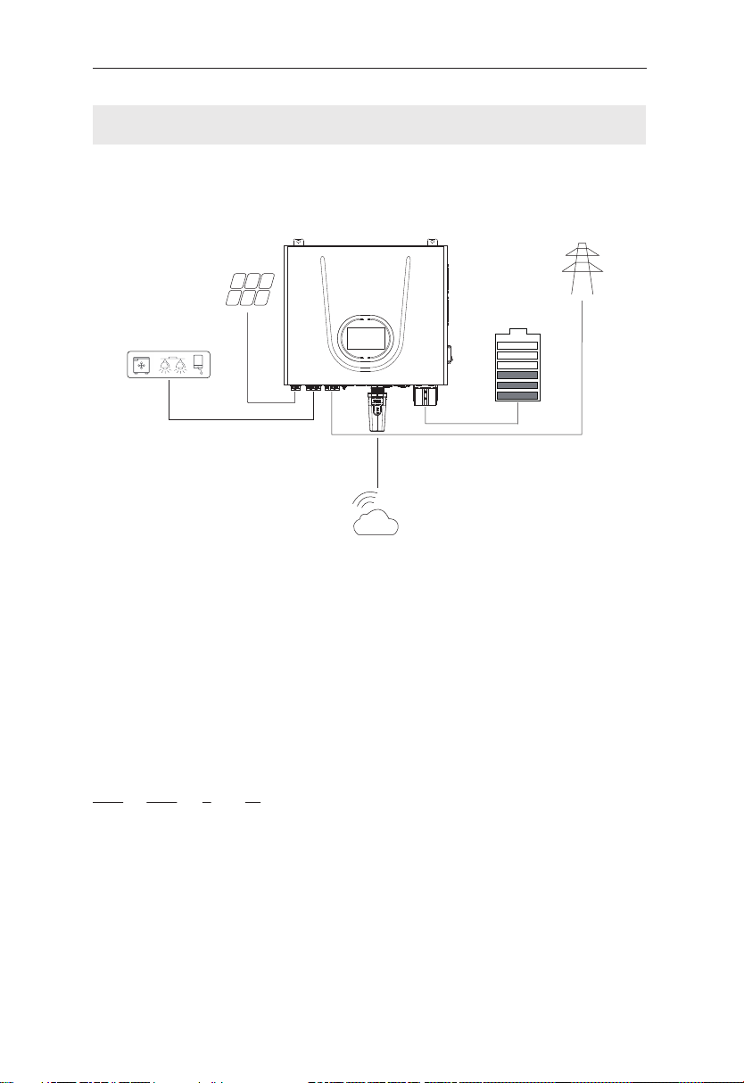
3.1 Scope of application............................................................................................05
3.2 Product Model Description...............................................................................05
3.3 Datasheet.................................................................................................................06
4 Installation Instructions ..........................................................................................07
4.1 Safety Tips ...............................................................................................................07
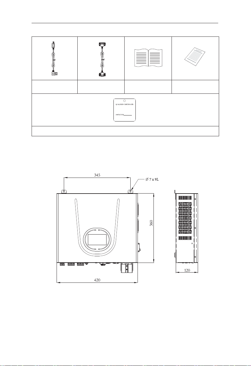
4.2 Packing List .............................................................................................................07
4.3 Determine the installation method and location ......................................08
4.4 Installation...............................................................................................................09
5 Electrical Connections..............................................................................................11
5.1 Electrical Interface Description ........................................................................11
5.2 System Wiring Schematic ..................................................................................11
5.3 Battery Wiring........................................................................................................11
5.4 PV Input Wiring .....................................................................................................13
5.5 AC in/AC out Wiring ............................................................................................13
5.6 Monitor Installation (optional).........................................................................14
6 Local Configuration...................................................................................................15
6.1 Local Interface Introduction..............................................................................15
6.2 Home Page..............................................................................................................15
6.3 Detail Info Page .....................................................................................................16
6.3.1 I/O Info Page ...............................................................................................16
6.3.2 System Info Page........................................................................................16
6.4 Fault Page ................................................................................................................17
6.5 Statistics Page ........................................................................................................18
6.6 Setting Page............................................................................................................19
6.6.1 Brightness Setting Page...........................................................................19
6.6.2 Inverter Setting Page................................................................................19
6.6.3 Version Page ................................................................................................29
6.6.4 Clear Page.....................................................................................................29
6.7 Start up the System..............................................................................................30
6.8 Shut Down the System........................................................................................30
7 Fault Codes and Common troubleshooting...................................................31
8 System Maintenance ................................................................................................36
8.1 Storage .....................................................................................................................36
8.2 Cleanliness...............................................................................................................36

02
1 Notes on this Manual
1.1 Scope
This manual is an integral part of UPC.
This manual describes the assembly, installation, commissioning, maintenance
and failure of the product. Please read it carefully before operating.
The manual is only for this batch of shipment.
1.2 Target Group
This manual is for qualified electricians. The tasks described in this manual only
can be performed by qualified personnel.
1.3 Symbols Used
The following types of safety instructions and general information appear in
this document as described below:
Danger!
“Danger” indicates a hazardous situation which, if not avoided,
will result in death or serious injury.
Warning!
“Warning” indicates a hazardous situation which, if not avoided,
could result in death or serious injury.
Caution!
“Caution” indicates a hazardous situation which, if not avoided,
could result in minor or moderate injury.
Note!
“Note” provides tips that are valuable for the optimal operation
of our product.
Off-Grid Inverter
UPC-3.5KSW UPC-5KSW UPC-5.5KSW
Danger
Warning
Caution
User Manual

03
2 Safety
2.1 Important Safety Instructions
Danger!
●Electric shock and high voltage.
●Do not expose the system to temperatures in excess of 45°C.
●Do not subject the system to any strong force.
●Do not touch uninsulated cable termination.
●Do not soak the system in water or expose it to moisture
environment.
●Do not touch the case of the system when it is wet in case of
electric shock.
●Do not place the system near a heat source, such as direct
sunlight, a fireplace.
●Keep inflammable and explosive dangerous items or flames
away from the system.
●Do not charge or discharge damaged system.
●
Before performing any work on the system, please disconnect
the system from all voltage sources as described in this document.
Warning!
●Installation, repair, recycling, and disposal of system must be
performed by qualified personnel in accordance with national
and local standards and regulations.
●Risks of chemical burn electrolyte or toxic gases.
●Do not place heavy objects on the top of the system.
●If the moisture penetrates the system (e.g., due to casing
damage), please do not install or operate the system.
●Do not use wet hands to touch the system.
●Any behavior to change the functionality of the product
without permission will cause fatal injury to the operator, third
parties, and equipment. UPC is not responsible for these losses
and warranty claims.
●To ensure property and personal safety, the UPC shall be well
grounded.
Danger
Warning
User Manual

04
This section explains all the symbols shown on the UPC and on the type label.
CE mark.
The system complies with the requirements of the applicable CE
guild lines.
Dangerous electrical voltage
The device is directly connected to public grid, thus all work to
the system shall only be carried out by qualified personnel.
Do not touch any internal parts of the UPC being disconnected
from the mains, battery and PV input for 5 minutes.
Danger of hot surface
The components inside the device will release a lot of heat
during operation. Do not touch metal plate housing of the UPC
during operating.
Danger.
Risk of electric shock!
An error occurred
Read the usage manual to troubleshoot problems
Recyclable
2.2 Explanation of Symbols
Caution!
●Do not modify or tamper with system and other components
of the system.
●Risk of injury by hoisting or falling system.
●
UPC is heavy and personal injury can be caused if the UPC is
improperly lifted or dropped during transport or improper oper-
ation when attached or removed from walls. Lifting and moved
the products shall be conducted by more than two people.
Note!
●Do not reverse output of these two AC terminals of the UPC.
Caution
User Manual

05
User Manual
In daytime, solar power supports the loads first while the surplus power will
be stored by system, to improve self-consumption rate.
In case of grid fault, system will make sure no outage in the loads, achieving
UPS function.
① UPC is the name of Off-Grid Inverter.
② 3.5K indicates the rated power of the system, such as 3.5K for 3.5kW.
③ S indicates that the system is a single-phase system.
④ W indicates a horizontal version of the product.
UPC - 3.5K SW
① ② ③ ④
3 Introduction
3.1 Scope of application
3.2 Product Model Description
Server

06
User Manual
3.3 Datasheet
Battery
Rated Voltage
Voltage Range
Max. Discharge Current
Max. Charge Current
Battery Type
AC Output (Backup)
Rated Power
Output Voltage
Output Frequency
Max Output Current
Rated Current
Peak Power
Over Load Ability [1]
Output Wave
Peak Efficiency (Battery Mode)
Transfer Time
AC Input
Input Sources
AC Input Voltage Range
Rated Input Voltage
AC input frequency
PV Input
Max PV Input Power
Max. PV Input Voltage
MPPT Voltage Range
Best Voltage Range
Max. DC Input Current
Max. DC Short Circuit Current
General Data
Range of working temperature
Optimal working temperature range
Storage temperature
Humidity
Cooling strategy
Altitude
Weight
Dimension [W x H x D]
Enclosure protection rating
Communication
Certificate
80A
80A
3500W
16A
15.2A
7000W
4500W
450Vdc
120~430Vdc
300~340Vdc
18A
20A
5500W 5500W
5000W
50/60Hz ± 1%
22.7A
21.7A
10000W
Battery Mode(Battery Max Output Current>200A):
1min@102~110% Load; 10s@110~130% Load;
3s@130~150% Load; 200ms@>150%Load
Pure Sine Wave
>92%
UPS Mode: 10ms/ APL Mode: 20ms
L+N+PE
APL Mode: 154~264Vac/ UPS Mode: 185~264Vac
208/220/230/240V
50/60Hz (Auto Adaptive)
5500W
26.4A
23.9A
11000W
110A
80A
125A [1]
80A
51.2V
44.8~57.6V
Charge: 0℃~50℃/Discharge: -10℃~55℃
20℃~30℃
-15℃~60℃
20-95% non-condensing
Fan
<1000m
10kg
420*360*120 mm
IP20
Wi-Fi (Optional)/RS485/CAN
CE
Li-ion (LFP)
Model UPC-3.5KSW UPC-5KSW UPC-5.5KSW
208/220/230/240Vac ± 5%
[1]More than two batteries need to be connected to satisfy

07
User Manual
4 Installation Instructions
4.1 Safety Tips
4.2 Packing List
UPC OFF-GRID Inverter
X 1 pcs
Tube Terminal Red
X 3 pcs
Tube Terminal Black
X 3 pcs
Tube Terminal Yellow
X 2 pcs
Monitor Module
(Optional)X 1 pcs
Expansion Screw
X 2 pcs
Network Cable (1.5m)
X 1 pcs
OT Terminal
X 2 pcs
Danger!
●
Potential fires and electric shocks that are life threatening.
●
Do not place any flammable or explosive materials beside system.
●
Equipment connected to high-voltage power generation equipment must be
performed by qualified personnel in compliance with national and local
standards and regulations.
Note!
●
The pollution level applicable to system is Class II.
●
Inappropriate or inconsistent installation environment can shorten the life of
system.
●
Do not install UPC directly by exposing it under strong sunlight.
●
Please do not install in damp places.
●
The installation location must be well ventilated.

08
UPC heat dissipation by fan cooling. It is recommended to install in indoors
or sheltered areas to avoid direct sunlight, rain and snow.
Please ensure that the air at the installation point is circulated. Bad air ventila-
tion will affect the working performance of internal electronic components
and shorten the service life of UPC.
User Manual
4.3 Determine the installation method and location
UPC dimension(mm):
USB Cable X 1 pcs Parallel Line (DB9) X 1 pcs User Manual X 1 pcs Packing List X 1 pcs
Qualified Certificate X 1 pcs

09
Wall-mounted installation
The device shall be indoor installed and vertical placed. The place where it is
installed shall be able to ensure the stability and safety of the product.
Step1: Drilling hole
Choose a suitable location to place the mounting bracket, and there should
be no obstructions within 200mm to avoid affecting heat dissipation. Put the
mounting bracket properly on the wall, mark these 2 drill holes using a
marker pen. Drill 2 holes on the wall, Insert the expansion screw vertically into
the hole.
User Manual
4.4 Installation
Crimper Knife Crimping Pliers (Tube Terminals)
Phillips Screwdriver Marker Pen Electric Drill

10
Step2: Installation
Lift the UPC up and install it according to the position of the screws on the
wall, tighten the nuts after installation.
User Manual
345 2- 8

11
User Manual
5 Electrical Connections
5.1 Electrical Interface Description
5.2 System Wiring Schematic
Object Description Object Description
1 PV Input 8 AC Output
2 Battery Input 9 Reset Button
3 BMS(CAN/RS485) port 10 COM(Wi-Fi) (Optional)
4 Dry port 11 Inverter Button
5 USB Type B port 12 LCD Screen
6
Parallel communication port
13 Battery Breaker
7 AC Input
5.3 Battery Wiring
Cable type
4 AWG 10 6.8
Outside diameter (mm) Conductor core section (mm)
Conductor Diameter (mm)
Server

12
User Manual
Step 1:Prepare the cable. The stripping operation must not cut any cable
strands, insulation or jacket at places other than specified by the cable
stripping dimensions. Take care that the individual strands of the cable are
not be bent and that the insulation or jacket is not damaged. The surface
must be clean and free of contamination.
Step 2:Apply the cable onto the crimping position
Before crimping, the center terminal must be positioned to fulfill following
conditions:
●
A max. air gap of 1 mm is allowed between the shoulder of the cable insulation.
Step 3:
Use a special tool to crimp the cable to ensure that the crimping is intact.
Step 4:Unscrew the battery cover screws and lock the positive and negative
battery cables.
Cable Color
BAT+ Red
BAT- Black

13
User Manual
5.4 PV Input Wiring
5.5 AC in/AC out Wiring
Note!
●Use 4 mm2 DC cable for the DC input cable.
●Remove the side bezel before installation.
Warning!
●Make sure that the DC voltage of each PV string is less than 450V and the
polarity of PV cables are correct.
●Ensure wiring is not energized.
Warning!
●Turn off the external AC breaker after unpacking in any cases before and
during wiring in case of electric shock.
Step 1:Prepare PV positive and negative power cables.
Cable Color
PV+ Red
PV- Black
Step 2:Insert the crimped photovoltaic positive and negative power cable
into the PV Input Terminal.

① Choose the right cable.
Step 1:
② Peel off the cable insulation sleeve for 12mm, as shown in Figure:
Step 2: Crimp terminals with special tools.
Step 3: Connect cable to AC in/AC out terminals.
14
User Manual
5.6 Monitor Installation (optional)
Cable type
10 AWG 4.9 3.22
Outside diameter (mm) Conductor core section (mm)
Conductor Diameter (mm)
Color
Red
Black
Yellow-green
Installation of monitor. Refer to the monitor's
manual (in the monitor box) for specific
instructions on how to use it.
Cable
L
N
PE

15
User Manual
UPC has a touch screen on the front.
6 Local Configuration
6.1 Local Interface Introduction
This page shows the total PV input power, AC grid power, battery power and
SOC, load power.
6.2 Home Page
Home Page
Detail Info Page
Fault Page
Statistics Page
Setting Page

16
User Manual
This page shows the PV, Grid, Load and Battery information.
6.3.1 I/O Info Page
This page shows the Work Mode, Batt. Type and other system information.
6.3.2 System Info Page
6.3 Detail Info Page
Work Mode
Chg Source
Batt ChgC.(A)
Batt Switch To Ac
AC Input
Out Volt.
AC ChgC.(A)
AC Switch to Batt
Batt. Type
Out Freq.
Bypass
Batt Cut-off
PV Grid Load Battery
Volt
Current
Power
Volt
Current
Power
Freq.
Volt
Current
Power
Freq.
Volt
Current
Power
SOC
V
A
W
V
A
W
Hz
V
A
W
%

17
User Manual
6.4 Fault Page
This page shows the real-time fault alarm and fault history of the system.
HistoryReal-time Alarm
Real-time Alarm History

18
User Manual
(KWH)
Production 0 0
0 0
Day Total
(KWH) Day Total
Discharge
Next
(KWH)
0 0
0 0
Day Total
(KWH) Day Total
Consump
Next
To Bat
To Load
These two pages show statistics info of Grid, Battery, PV and Load.
6.5 Statistics Page
This manual suits for next models
3
Table of contents
Popular Inverter manuals by other brands

Joranalogue
Joranalogue GENERATE 3 manual

Xantrex
Xantrex ENERGY HW 1000 owner's guide

WPool
WPool WPS 40 Installation and user guide

Carbest
Carbest 82285 User instruction

Generac Power Systems
Generac Power Systems PWRcell XVT076A03 Installation and owner's manual

SolarEdge
SolarEdge SE K Series Quick installation guide

Sofar
Sofar HYD 5KTL-3PH user manual

Ozone Solutions
Ozone Solutions Waterzone Series Installation & operation manual

Power Electronics
Power Electronics SD 300 Series Getting started manual

Wagan
Wagan Elite 3000W user guide

Steca
Steca coolcept3 StecaGrid 3203 Installation and operating instructions

Phaesun
Phaesun Tre King quick guide