DASS Tech Soleaf DASS 100i Specification sheet

DASSTECH Photovoltaic Grid-
Connected Inverter
[Grid connected type Photovoltaic Inverter]
DASS 100i
[DSP-33100E-OD-HV]
Version 1.0
Operation and Installation Manual

1
Table of Contents
1. Precautions for Safety…..........................................................................................................3
1.1 Symbols Used in the Manual...................................................................................................................................4
1.2 Symbols Used in the Inverter………….....................................................................................................................5
1.3 Precautions while Operating.……….....................................................................................................................6
2. Product Overview....................................................................................................................8
2.1 Basics……….......................................................................................................................................................8
2.2 Appearance of the Product........................................................................................................................8
2.3 Verification of the Product..........................................................................................................................9
2.4 Configuration of the Product...................................................................................................................10
2.5 Dimensions of the Product.......................................................................................................................12
2.6 Configuration of the Photovoltaic System............................................................................................13
2.7 Features of the Product.............................................................................................................................14
3. Installation.............................................................................................................................15
3.1 Transportation..............................................................................................................................................15
3.2 Installation Place.........................................................................................................................................16
3.3 Cautions While Installation.......................................................................................................................17
3.4 Installation Method.....................................................................................................................................19
3.5 Block Diagram..............................................................................................................................................21
3.6 Precautions during Wiring........................................................................................................................21
3.7 DC Connection…………………………………………………………………………………………………...………23
3.8 AC Connection and Grounding Connection …………………………………………………………...……24
3.9 RS485 Communication Connection.......................................................................................................27
3.10 Active Voltage Control Setting........................................................................................................29

2
4. Design Guide of High Voltage Transformer for Central Inverter Design Guide................30
4.1 Technical Properties..................................................................................... .........................................................30
4.2 Requirements of the mid-voltage power transformer connected to the (single) central
inverter…………………………………………………………………………………………………………………………………….31
4.3 Requirements of the mid-voltage power transformer connected to the (double) central
inverters………………………………………………………………………………………………….…………............................34
4.4 Winding Technology ............................................................................................................................................37
5. Operation...............................................................................................................................39
5.1 Checklist prior to Operation …….........................................................................................................................39
5.2 Appearance of the Display Window and Functions...................................................................................39
5.3 Display Window Screen …………...........................................................................................................................40
5.4 How to Operate..........................................................................................................................................................42
6. Functions...............................................................................................................................42
6.1 Description of Functions.......................................................................................................................................43
6.2 Symptoms of Warning and Fault......................................................................................................................45
6.3 Types of Main Faults...............................................................................................................................................45
6.4 Types of Faults and Corrective Actions..........................................................................................................47
6.5 Types of Warnings and Corrective Actions...................................................................................................49
6.6 Failure Repair..............................................................................................................................................................50
6.7 Disposal ………............................................................................................................................................................50
7. Maintenance and Cleaning….........................................................................................51
8. Product Specifications..........................................................................................................52
9. Warranty................................................................................................................................54
3
1. Precautions for Safety
Precautions for safety aim for safe and correct operation of the products by preventing
accidents or hazards in advance, so you must follow them at all times.
In order to properly and safely use the functions of DSP inverter series, read the manual
carefully.
After reading the operation and installation manual, please store it in a place where all users
can easily find and read it.
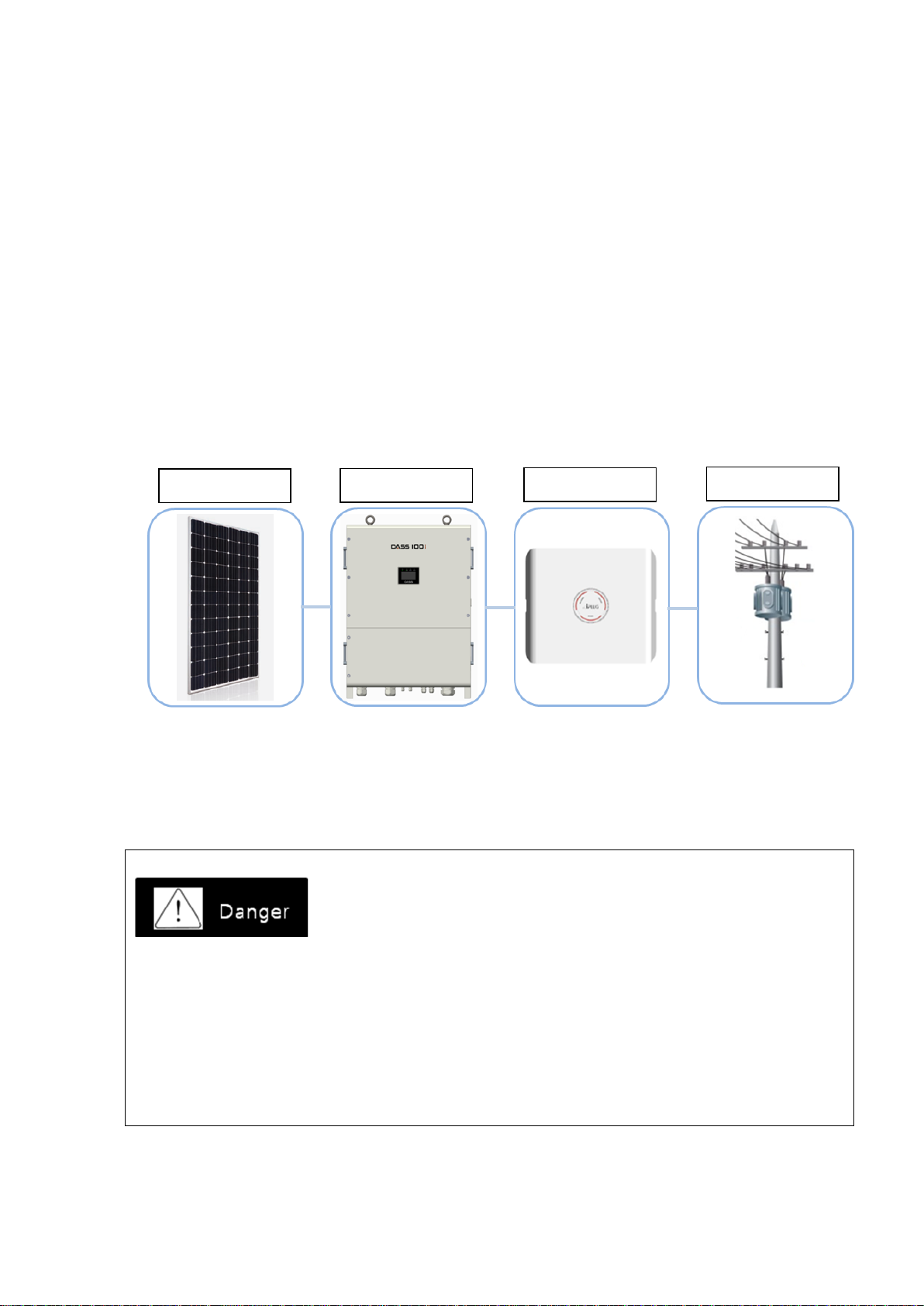
DSP series inverter is a grid-connected PV inverter that transforms direct current of PV
generator into alternate current and connects to the system.
※The DSP series inverter must only be operated with PV arrays of protection class II in accordance
with IEC 61730, application class A. DSP series inverter shouldn’t be connected to any energy source
other than PV module
Deadly risk due to the high voltage of the inverter
When the photovoltaic generator array is exposed to the light, dangerous DC voltage on the
DC conductor or the conductive parts of the inverter can be generated. If you are contact on
the DC conductor or the conductive parts, you may be deadly shocked by electricity.
Use caution not to be contacted on the DC conductor.
Use caution not to be contacted on the live conductive parts of the inverter.
Separate the inverter from all power sources before you carry out any work on the inverter.
PV Module
PV Inverter
Monitoring
Grid
4
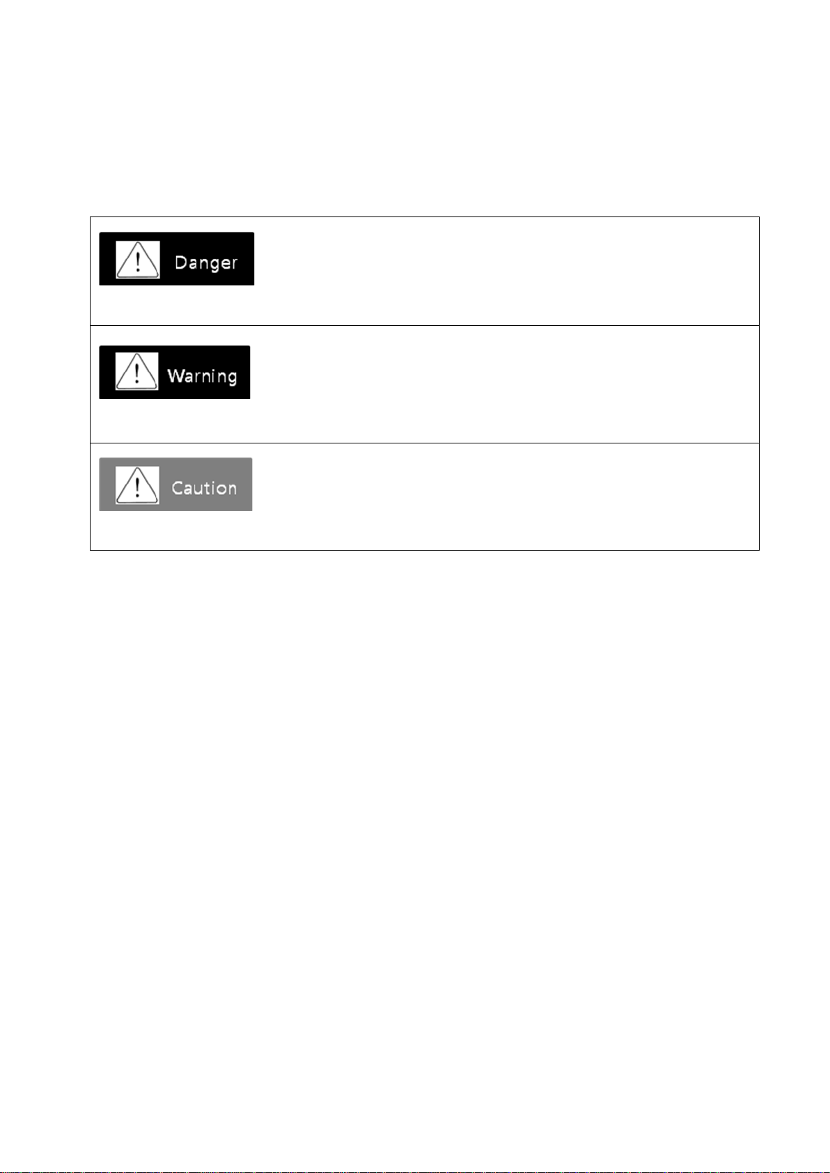
1.1 Symbols Used in the Manual
The meaning of the symbols used in the manual is as follows:
Danger indicates a hazardous situation which, if not avoided, will result in death or serious injury
Warning indicates a hazardous situation which, if not avoided, can result in death or serious injury
Caution indicates a hazardous situation which, if not avoided, can result in minor or moderate injury
5
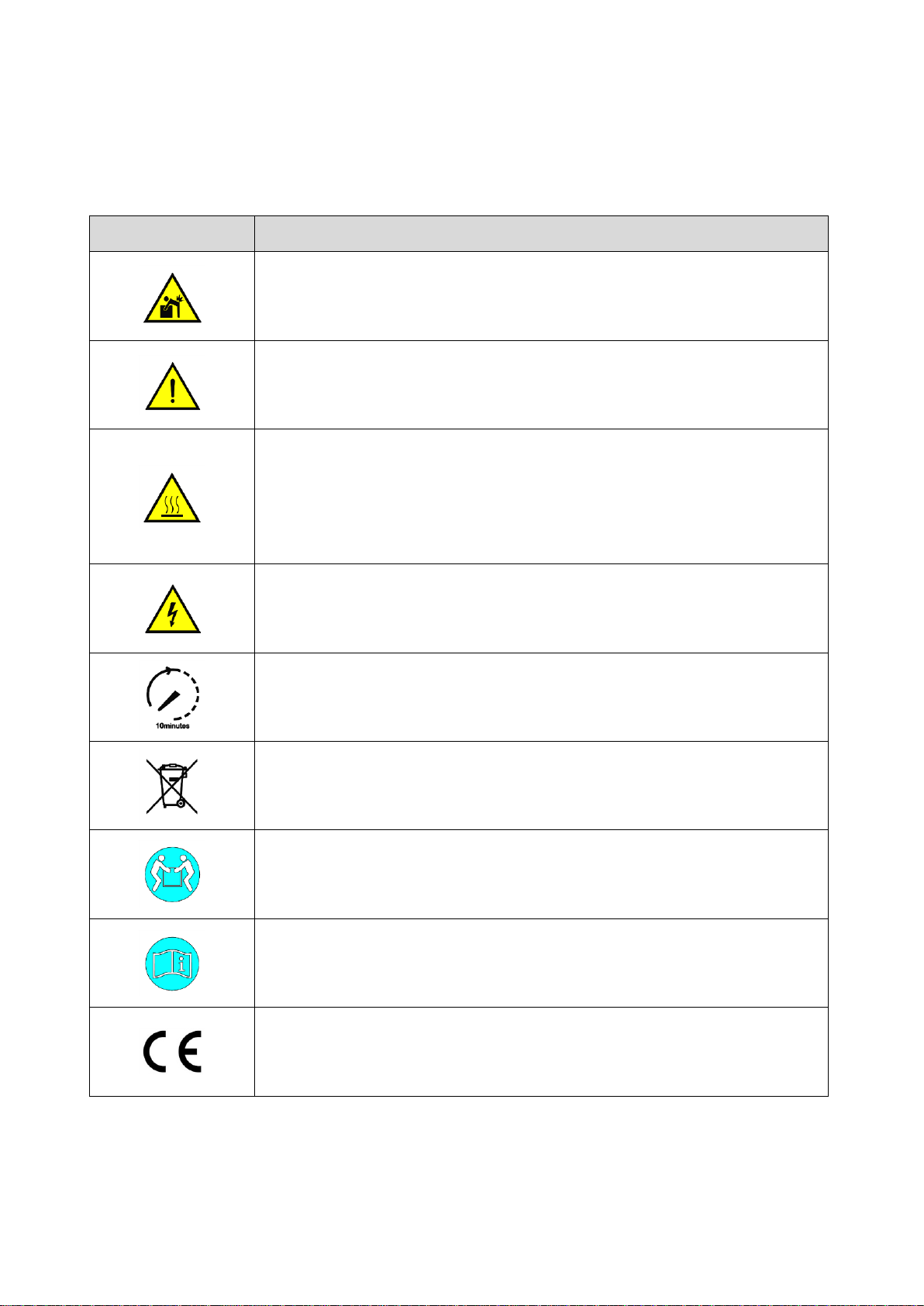
1.2 Symbols Used in the Inverter
The meaning of the symbols used in the inverter is as follows:
Symbol
Description
Do not lift up or move the product alone.
Keep the connection requirements of secondary protective conductor.
Refer to Ground Connection in page 26.
The product can be heated during the inverter’s operation. Do not touch the
inverter enclosure during operation.
Before carrying out any work, you should wait for the product cooled down
completely.
Wear safety gloves and personal protective equipment.
The product is worked on a high pressure. All works related with the inverter
must be performed by a professional electric engineer.
The capacitor of the inverter may charged with very high voltage.
Se[arate the inverter from all power sources and wait for 10 minutes or longer
before your work in order for the capacitor to be discharged.
Follow the local electronic waste regulations when disposing the inverter.
Transport the product by 2 persons or more or use dedicated equipment.
Follow the instructions in the manual provided with the inverter.
This product is complied with the corresponding CE requirements.

6
1.3 Precautions while Operating
Do not operate the product when the front cover is opened.
It can cause electric shock as the high-voltage terminals or live parts can be exposed.
Do not operate the switch with wet hands.
It can cause electric shock.
Do not open the cover when power is already on or during operation.
It can cause electric shock.
Even if power is not on, do not open the front cover except for regular inspection time.
Even under off-power, voltage can be charged in the internal capacitor of the inverter, which can
cause electric shock.
Check if the DC voltage of the inverter is discharged by using a measurement tool such as
volt-ohm-milliampere (VOM) after 10 min or longer from power off when wiring work or
regular inspection is performed.
Since high voltage can be charged in the internal capacitor of the inverter, it can cause
electric shock.
Do not use the product if the sheath of the cable is damaged.
It can cause electric shock.
Do not place a heavy object that gives excessive stress on the cable while using.
It can cause electric shock due to the damage on the sheath of the cable.
Do not supply power even if the installation is complete when part of the inverter is
damaged.
It can cause electric shock.

7
Do not install the product near any flammable materials.
If the product is installed with flammable materials or attached near flammable substance, it can
cause a fire.
Disconnect the input power (solar cells) and output power (AC system power) in the inverter
during inverter failure.
If the power is not disconnected, it can cause a fire due to the secondary accident.
Do not touch the front or upper surface of the inverter enclosure during inverter operation.
The front or upper surface of the enclosure can be hot, which can cause a burn.
Do not touch the inverter while power is connected or within 30 min after power is
disconnected.
Since the product is on a high-temperature, it can cause a burn when the product is contacted
with human body.
Do not supply power even if the installation is complete when the inverter is damaged.
It can cause electric shock and additional part damage.
Do not have foreign substances such as screws, metal parts, water or oil get into the inside of
the inverter.
It can cause a fire.
Keep the distance of at least 30 cm from the inverter.
It can risk health due to the emission effect.

8
2. Product Overview
2.1 Basics
If the inverter is operated incorrectly, it can prevent normal operation or reduce a lifespan of the
product. In the worst case, the inverter can be broken or incur fatal damage to human bodies. Therefore,
please read carefully and understand thoroughly the operation and installation manual prior to the use.
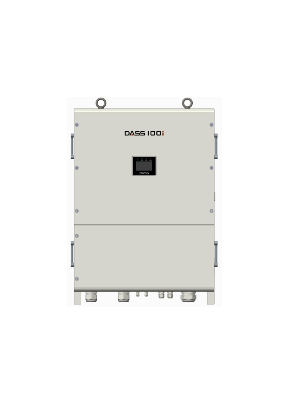
2.2 Appearance of the Product
9
2.3 Verification of the Product
Please check the name plate at the side of the main product body whether inverter type and
rated output are matched with the ordered product details once the inverter is taken out of the
packaging box. In addition, check whether there is any damage during transportation.
Inverter TYPE
Accessories/tools
- Please contact the office if there are some missing accessories such as the operation and
installation manual, fixed bracket, bracket fixing bolts and hexagon
wrench or if the product is damaged.
- Depending on the operation field, necessary tools can be different and should be prepared
well. (e.g: Multi-tester to check voltage and wiring, power tools to install fixed brackets etc.)
10
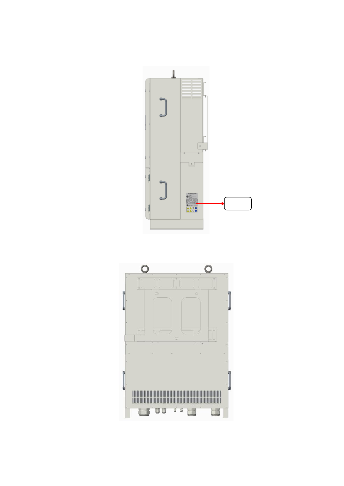
2.4 Configuration of the Product
Front view
11
Side view
Rear view
명판

12
Bottom view
Item
Name
Description
①
PV(+) Input Port
Input PV(+) cable gland
②
PV(-) Input Port
Input PV(-) cable gland
③
COM1, COM2
485 communication (IN, OUT)
④
ANT
Wifi cable (option)
⑤
AC Output Port
Output AC cable gland
⑥
Protective Vent
Pressure balance Vent
⑦
F.G
Grounding connection terminal
⑧
COM3, COM4
Active voltage control communication (IN,OUT)
2.5 Dimensions of the Product
①
②
③
④
⑤
⑥
⑦
⑧
PG48 Cable gland
CV 70SQ 4core
PG36 Cable gland
CV 70SQ single core
PG7 Cable gland /
Communication

13
2.6 Configuration of the Photovoltaic System
With arranging necessary equipment correctly, the inverter shall be connected well.
With the wrong system configuration and connection, it can cause abnormal operation or reduce
a lifespan of the product seriously.
In the worst case, the inverter can be damaged, so please use the product well according to the
contents and precautions in the manual.
In case of using non-grounded PV module, the module should comply with IEC 61730 Class A.
PV array should not be grounded.

14
2.7 Features of the Product
High-efficiency power conversion
PWM method with IGBT semi-conductor device is applied and the high-efficiency of 98% or
higher can be achieved at the rated power.
Digital control
The system is controlled efficiently through the high-performance digital control and it can be
checked through LCD keypad to monitor and display the operation of the inverter including
input/output status, also fault conditions to terminate the operation.
Also, by detecting a voltage in the solar module, the inverter is operated or terminated
automatically.
Transformer-less inverter
As this outdoor type inverter is a transformer-less type, it is suitable for distributed power
systems designed for a commercial scale generation.
Distributed power system and economic feasibility
The photovoltaic system can be installed anywhere where the sunlight is available. Thus,
distributed power can be constructed at a level of building, house, or solar power plant,
which can be used economically.
Maximum Power Point Tracking (MPPT)
Since the output characteristic of the solar cell is to generate, not uniform DC depending on
temperature, humidity, climate, environment, and insolation, the inverter controls the solar cell
module to maintain the maximum power point through the Maximum Power Point Tracking
(MPPT) control.
Easy parallel operation
Once the capacity of the solar cell module is increased, the inverter can be added without
additional equipment via parallel connection easily.

15
Simplicity of operation
The inverter is designed to display the status in real time through the front LCD screen.
3. Installation
3.1 Transportation
Please transport the product correctly according to the weight of the product.
Do not stack the product beyond the restricted limit.
Move the unit by 4 persons or more or with the lifting device because the weights of the
inverter and packaging box are 85kg and 10kg.
Do not open the front cover during transportation of the product.

16
Please check the outer appearance of the product whether there are no fault appearances
found.
Do not drag or throw the inverter.
Since the inverter is a precise apparatus, do not drop the inverter or give any strong impact.
3.2 Installation Place
Caution
Please install the product at a place where the following conditions are met.
The inverter should be installed at a place where there is no direct sun light considering
installation direction or surrounding space to prevent reduction in lifespan or performance
degradation.
The product can be installed at indoor or outdoor place.
The inverter should be installed at a well-ventilated place if it is installed indoor.
Do not install the product at a vibrated place.
Do not install the product at the concrete wall as much as possible.
A lifespan of the inverter can be affected by an ambient temperature. Please make sure the
ambient temperature at the installed place does not exceed an allowable storage temperature
(-25 ~ 50℃).
Please avoid a place with high temperature and humidity (relative humidity is 90% or less
and no dew formation).
Since the inverter is high-temperature heating element, please install the inverter on the
surface of fire retardant material.
Please make sure facilitating heat dissipation by ensuring a space around the inverter.
Please avoid the place where there are oil mist, flammable gas, fiber dust, dust, and moisture.
Please install the product sturdily with the bolts.
Please install the product at a place without salinity. (In particular, if the product is installed
near the coastal area, product corrosion can occur. Thus, contact with salinity should be
avoided using additional methods such as installing an additional enclosure and indoor
installation.)

17
3.3 Cautions While Installation
Please install the product according to the contents in the manual.
The installation place should be clean at all times and can be accessed safely without using
auxiliary means such as lifting platform or foothold. Otherwise, service work may be limited.
The connecting part (bottom surface of the inverter) should be directed to the below.
Do not install the product at a tilted condition.
Do not install the product horizontally.
Please install the product at a place without high humidity and dust as well as direct sunlight,
and the product should not be close to high-temperature heat-generating part. Generated
power can be reduced due to overheating.
The installation work must be done by professional technician.
Do not place a heavy object on the product.
Do not spray or place flammable substances near the product.
The installation direction must be followed in accordance in the information in the operation
manual.
Since the inverter is a precise apparatus, do not drop the inverter or give any strong impact.
The inverter requires grounding work of 3-type(200V grade) or special 3-type (400 V grade).
Do not use other electronic appliances near the product. Failure or noise in the electronic
appliances may occur.
18
Be sure to use the exclusive bracket, and use caution due to the sharp part.
Prior to installing the inverter, DC switch installed at the lower end of the inverter should be
OFF. If it is ON, it can be a cause of a failure during installation. Upon installation completion,
the inverter should be ON, and then make the inverter operated.
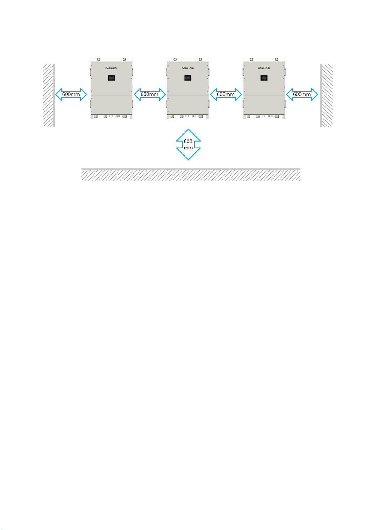
At least 60cm of space at the upper part as well as left and right side of the inverter should
be secured when the product is installed in the indoor.
At least 60cm of space should be secured from the ground when the product is installed in
the indoor or outdoor.
60cm or more of space between inverters should be secured when the product is installed in
parallel.

19
3.4 Installation Method
Please refer to the below photo for the installation method.
After the fixing bracket is installed, the inverter is placed on the bracket and fastened by
the bolts.
Caution
At least 4 or more persons must install the inverter during lifting or fixing it to the bracket.
Because the product is heavy, pls. install the product by a lift or crane possibly.
Since a weight of the inverter is 85kg, deal with it carefully, not to drop the inverter.
Table of contents
Other DASS Tech Inverter manuals


Popular Inverter manuals by other brands

Shindaiwa
Shindaiwa DGW201M Owner's and operator's manual

Mitsubishi
Mitsubishi FR-A7NC instruction manual

Power One
Power One Aurora PVI-3.8/4.6-I-OUTD Installation and operating manual

Mitsubishi Electric
Mitsubishi Electric 800 Series instruction manual

SMA
SMA SBCBTL6 installation guide

Envertech
Envertech EVT800 Quick installation guide


