Data Aire DAMA-01 Instruction manual


2
CONGRATULATIONS ON THE SELECTION OF A
DATA
AIRE PRECISION ENVIRONMENTAL
CONTROL SYSTEM. PROPER INSTALLATION,
OPERATION
AND MAINTENANCE OF THIS
EQUIPMENT WILL ENSURE YEARS OF OPTIMAL PERFORMANCE.
There are separate Installation, Operation and Maintenance and User Manuals for other components
of your Data Aire precision environmental cooling system including Mini-dap4 microprocessor
controller and condenser/condensing unit and fluid cooler.
NOTE: This manual is intended to assist trained service personnel by
providing necessary guidelines for this equipment. Service to Data Aire units
should be done by qualified individuals with an adequate background in areas
such as HVAC, electrical, plumbing and electronics, as applicable.
WARNING: Service performed by unauthorized or unqualified
technicians may void manufacturers’ warranties and could result in
property damage and/or personal injury.
Safety Alert Symbols and Words for Hazard Alerting Safety
DANGER: Indicates a hazardous situation which, if not avoided, will result
in serious injury or death
WARNING: Indicates a hazardous
situation
which, if not avoided, could
result
in serious injury or
de
ath.
CAUTION: Indicates a hazardous situation which, if not avoided, could
result in minor or moderate injury.
NOTICE: Indicates information considered important but may have potential
hazard for personal injury or property damage.
Data Aire, Inc. reserves the right to make design changes for the purpose
of product improvement or to withdraw any design without notice.

TABLE OF CONTENTS
3
INTRODUCTION............................................................................................................. 7
Product Information.......................................................................................................................7
Model Identification .......................................................................................................................7
Inspection......................................................................................................................................8
Paperwork.....................................................................................................................................8
Storage..........................................................................................................................................9
Suggested Reference Storage Room Conditions.........................................................................9
General Storage Considerations...................................................................................................9
Registered Trademarks –Copy Rights –References Section...................................................10
INSTALLATION.............................................................................................................11
Recommended Tools for Installation ..........................................................................................12
Pre-Installation ............................................................................................................................12
Installation must be planned so that: ..........................................................................................12
Room Considerations..................................................................................................................13
Equipment Handling and Rigging ...............................................................................................14
Moving Unit into Final Location...........................................................................................14
Rigging........................................................................................................................................14
Locating the Unit .........................................................................................................................14
Horizontal Airflow Units...............................................................................................................15
Installing/Mounting ......................................................................................................................15
Vertical Airflow Units ...................................................................................................................16
Air Cooled Packaged Units.........................................................................................................17
Indoor Condensers and Condensing Units.................................................................................18
Piping ..........................................................................................................................................18
Split Air-Cooled Unit Piping.........................................................................................................19
Discharge Lines ..........................................................................................................................19
Liquid Lines .................................................................................................................................21
Suction Lines...............................................................................................................................21
Recommended Line
Sizing
........................................................................................................21
Hot Gas Lines......................................................................................................................22
Liquid Lines.........................................................................................................................22
Suction Lines.......................................................................................................................22
Connection Sizes, Air-Cooled Units............................................................................................23
Connection Sizes, Water/Glycol Cooled Units............................................................................23
Connection Sizes, Chilled Water Units .......................................................................................23
Field Piping, Remote Condenser/Condensing Unit Above Evaporator ......................................24
Field Piping, Remote Condenser/ Condensing Unit Below Evaporator......................................25
Connection Sizes, Fluid Cooler (Dry Cooler)..............................................................................26
Condensate Drain System..........................................................................................................26
Condensate Trap.................................................................................................................27
Condensate Pump Side Mounting Pump (Optional)...........................................................29
Humidifier....................................................................................................................................30
Steam Generator Humidifier ...............................................................................................30
Humidifier Piping.................................................................................................................30
Refrigerant Piping Protection......................................................................................................30
Water/Glycol Cooled Unit Piping.................................................................................................31
Leak Testing................................................................................................................................33
Electrical Installation ...................................................................................................................33
Commissioning Information.........................................................................................................34
ELECTRICAL CONNECTIONS......................................................................................35
TABLE OF CONTENTS
4
General Electrical Field Wiring Guidelines..................................................................................36
Electrical Service.........................................................................................................................37
Nameplate Ratings......................................................................................................................37
Grounding....................................................................................................................................37
Voltage Tolerance.......................................................................................................................37
Three Phase Voltage Tolerance .........................................................................................37
Single-Phase Voltage Tolerance.........................................................................................38
Heat Exchanger Auxiliary Control Wiring....................................................................................38
Remote Shutdown.......................................................................................................................39
Mini-dap4 Controller....................................................................................................................39
Remote Alarm Contacts..............................................................................................................39
Remote Sensors .........................................................................................................................40
Condensate Pumps.....................................................................................................................40
Disconnect Switch (Optional)......................................................................................................40
Manual Override Switch Board ...................................................................................................41
Wiring Diagrams..........................................................................................................................42
INSTALLATIONOF REMOTE OUTDOOR HEAT EXCHANGER....................................42
CHARGING....................................................................................................................43
Package Air-Cooled Systems .....................................................................................................43
Charging/Installation Work Procedures ......................................................................................43
Triple Evacuation and Dehydration Procedure...........................................................................43
Tools Needed......................................................................................................................44
First Stage Evacuation........................................................................................................44
Second Stage Evacuation...................................................................................................45
Third Stage Evacuation.......................................................................................................45
Final Evacuation Stage .......................................................................................................46
General Pre-Charging Guidelines...............................................................................................46
Voltage Phase Check..................................................................................................................47
Evaporator Power Phase Check.........................................................................................47
Fixed Speed Scroll Compressor Phase Check...................................................................47
Heat Exchanger Phase Check............................................................................................48
GHRC Air-Cooled Heat Exchanger Phase Check..............................................................48
DARC Heat Exchangers Phase Check...............................................................................48
Line Set Charge Calculations......................................................................................................48
Component Functional Test........................................................................................................49
Charging Procedures ..................................................................................................................49
Refrigerant Handling ...........................................................................................................50
Air-Cooled Split System Charging.......................................................................................50
Charging the Fixed Speed Compressor..............................................................................52
Additional Oil .......................................................................................................................54
Flooded System Charging (Systems with Low Ambient Receiver Package)......................54
Refrigerant Receiver ...........................................................................................................55
Applications.........................................................................................................................55
Selection Guidelines ...........................................................................................................55
Receiver Location................................................................................................................56
Safety Relief Devices..........................................................................................................56
Receiver Installation............................................................................................................56
Charge Fixed Speed Compressor.......................................................................................58
Water/Glycol-Cooled System Charging ..............................................................................58
Important Refrigeration Components..........................................................................................60
Thermal Expansion Valve ...................................................................................................60
High Pressure Cutout Switch ..............................................................................................60
TABLE OF CONTENTS
5
Low Pressure Cutout Switch...............................................................................................60
Liquid Line Solenoid Valve ..................................................................................................61
GLYCOL SYSTEMS ......................................................................................................62
Glycol Concentration...................................................................................................................62
Internal (Fluid) Volume................................................................................................................62
Fluid Cooler Internal Volume...............................................................................................62
Brazed-Plate Fin Condensers.............................................................................................62
Water Treatment..................................................................................................................63
Fluid Cooler.................................................................................................................................64
Type L Copper Tubing Internal Volume......................................................................................65
Freezing Point of Aqueous Solutions..........................................................................................65
Mixing Glycol and Water .............................................................................................................65
CONTROLS...................................................................................................................67
Programmable Thermostat .........................................................................................................67
Mini-dap4 Microprocessor Control Controller .............................................................................67
Optional Expanded dap4 Microprocessor Controller..................................................................67
Remote Heat Exchangers...........................................................................................................67
REGULAR MAINTENANCE ITEMS...............................................................................68
Air Filters.....................................................................................................................................68
Belts ............................................................................................................................................68
Bearings......................................................................................................................................68
Fuses...........................................................................................................................................69
Electric Reheat (Optional)...........................................................................................................69
Humidifier (Optional) ...................................................................................................................69
Humidifier Canisters............................................................................................................69
Refrigerant Filter Drier.................................................................................................................69
EC Plenum (Plug) Fans ..............................................................................................................70
Electronically Commutated Motors......................................................................................70
EC Motor Testing ................................................................................................................71
MAINTENANCE/INSPECTION CHECKLIST.................................................................72
Frequently Asked Questions –FAQ............................................................................75
Electrical FAQ Section................................................................................................................75
Mechanical FAQ Section.............................................................................................................76
Contact Data Aire .........................................................................................................79
TABLE OF FIGURES
Figure 1 Typical Installation...........................................................................................16
Figure 2 Unit with Vertical Plenum Mounting Method and Condenser Installation........17
Figure 3 Typical Discharge Check Valve.......................................................................20
Figure 4 Recommended Condensate Trap Dimensions................................................28
Figure 5 Typical Side Pump Mounting...........................................................................29
Figure 6 Typical Water/Glycol System ..........................................................................32
Figure 7 Typical Remote Heat Exchanger Interconnection Points................................39
Figure 8 Typical Indoor Evaporator Interconnection Points...........................................39
Figure 9 Manual Override Switch Board........................................................................41
Figure 10 Typical Low Ambient Receiver Package.......................................................57
Figure 11 Example Remote EPO Switch Connection....................................................76

TABLE OF CONTENTS
6
LIST OF TABLES
Table 1 Line Size Metric Conversion.............................................................................21
Table 2 Hot Gas Lines (Inches OD) ..............................................................................22
Table 3 Liquid Lines (Inches OD)).................................................................................22
Table 4 Suction Lines (Inches OD) ...............................................................................22
Table 5 Connection Sizes, Air-Cooled Units (Inches OD).............................................23
Table 6 Connection Sizes, Water/Glycol Cooled Units (Inches OD) to Remote
Condenser.....................................................................................................................23
Table 7 Connection Sizes, Chilled Water Units (Inches OD).........................................23
Table 8 Three Phase Voltage Tolerance.......................................................................38
Table 9 Single Phase Voltage Tolerance......................................................................38
Table 10 Remote Alarm Contacts Terminals.................................................................40
Table 11 Liquid Line Multiplier.......................................................................................48
Table 12 Liquid Line Multiplier for R-410A at Various Line Lengths..............................49
Table 13 Liquid Line Multiplier for R-407C at Various Line Lengths..............................49
Table 14 DAMA Starting Charge R-410A......................................................................51
Table 15 DAMA Starting Charge R-407C......................................................................51
Table 16 Refrigerant Charge Values.............................................................................53
Table 17 Refrigerant Receiver Charging Chart.............................................................58
Table 18 Discharge Head Pressure ..............................................................................58
Table 19 Packaged Units without Receivers.................................................................59
Table 20 Packaged Units with Receivers......................................................................59
Table 21 High Pressure Cutout Switch Setting .............................................................60
Table 22 Low Pressure Cutout Switch Setting..............................................................60
Table 23 Mini Ceiling Unit Internal (Fluid) Volume.........................................................62
Table 24 Type L Copper Tubing Internal Volume..........................................................65
Table 25 Freezing Point of Aqueous Solutions .............................................................65
7
INTRODUCTION
Product Information
The Data Aire Mini (DAM) environmental control, direct expansion, single circuit or chilled water-cooled
Computer Room Air Conditioner (CRAC) equipment provides a high sensible cooling, is self-contained,
factory assembled, piped, wired, and factory tested prior to shipment. These units include an
enclosure/cabinet assembly, fan section, filter section, cooling coils, controls, and interconnecting
piping internal to unit. This unit is normally mounted above the ceiling tiles.
The Data Aire CRAC unit provides cooling, reheat, humidification, dehumidification and air filtration.
The unit is provided with a Data Aire Mini-dap4 microprocessor controller for precision control. The unit
must be operated in a conditioned space within the operating envelope ASHRAE recommends for data
centers. Operating outside this envelope can alter the operating performance and decrease equipment
reliability. Return air to the unit must be no cooler than the ASHRAE recommendation for proper unit
operation. Operating below this can alter the operating performance and decrease equipment reliability.
Refer to ASHRAE’s publication, “Thermal Guidelines for Data Processing Environments.”
Model Identification
DAM X - XX X X - XX
Mini Ceiling System (DAM) Model Number
Configuration
DAM
1 - Single phase
2.5
Phase
01
1.5
02
Type of Cooling
Model Series
C - Chilled Water
A - Air Cooled
W - Water Cooled
G - Glycol Cooled
Nominal Capacity in Tons
CO - Split System with
outdoor condenser (GHRC or DARC)
P - Package System
CI - Split system with
indoor condenser (DAIC)
2 - 208, 230 or 277VAC
AO - Split System with
outdoor condensing unit (GHCU or DACU)
AI - Split System with
indoor condensing unit (DAAC)
Voltage

8
Model Identification Notes:
1. Condenser –A condenser coil (indoor or outdoor) but no compressor
2. Condensing Unit –a condenser coil (indoor or outdoor) which includes a compressor
3. The purchase order write-up should have the condenser or condensing unit model number.
Refer to applicable condenser or condensing unit model number identification.
EXAMPLE: Data Aire Mini, air-cooled, 2-Ton, single phase 230V, package system with outdoor
condensing unit:
Evaporator Model: DAMA 0212-AO
Condensing Unit Model: GHCU 0312 or DACU-0312
Inspection
This Data Aire CRAC unit has been factory run tested and has gone through a comprehensive
inspection prior to its packaging and shipment to ensure that it arrives in excellent condition. However,
shipping damage can occur and a visual inspection of the outer crating immediately upon delivery
should be performed. Upon arrival of the unit and before unpacking, verify that the labeled equipment
matches the bill of lading.
Loose items such as remote-control panels, disconnect switch handles, and spare air filters are packed
inside the unit. Refer to the yellow shipping tag located on the unit door for details.
NOTICE: Any external damage or transportation damage on the freight
carrier’s forms. Inspect the unit itself for internal damage. A claim should be
filed with the shipping company if the equipment is damaged or incomplete.
NOTICE: Freight damage claims are the responsibility of the purchaser.
Action to recover losses should be filed immediately. Please notify factory
personnel of any claims.
Paperwork
Each Data Aire CRAC unit ships with a startup sheet that should be completed during installation. Also
included in the paperwork is a warranty/information packet that provides important wiring diagrams,
specific component literature, warranty registration cards and other valuable paperwork, including a
copy of this Installation, Operation, and Maintenance manual.
A yellow tag isattached to the outsidedecorative door to indicate articles that mayhave been packaged
and shipped loose within the unit cabinet. Typically, this would be jackstands, condensate pumps and
other loose components that are not factory mounted.
WARNING: It is the responsibility of the installing contractor to return the
startup sheet and warranty registration card to Data Aire for proper
activation of the unit warranty. Failure to do so may cause delays and
some cases void the warranty

9
Storage
Short-term storage is considered 60 days or less from shipment date. Long-term storage is considered
any period beyond 60 days from date of shipment.
It is mandatory that a detailed record be maintained during this long-term storage period, such as, but
not limited to proper sealing of the cabinet, rotation of the blowers and bearings, and protection of all
motors from moisture. Check the fan rotation monthly, the fan and motor should be rotated several
times to replenish the bearing surfaces with fresh grease as needed and to prevent flat spots of the fan
shaft. The fan impeller should be left at approximately 180° from that of the previous month to prevent
the belts from taking a set position.
If equipment is stored for longer than 60 days special precautions must be taken to avoid coil damage.
All coils should be charged and sealed with a low pressure 1 to 3 PSIG (6.9 to 20.7 kPa) inert gas, such
as nitrogen. This prevents contaminates from entering the coils; then when the seal is broken at
installation, the rush of escaping gas verifies the coil is still leak free. If coils are not charged and sealed,
condensation mixes with air pollutants forming a weak acid and over time can cause pin hole leaks to
develop in the coil tubes.
It is the responsibility of the customer to submit a monthly log sheet showing the condition of the unit
and noting any discrepancies. A copy of the log sheet should be sent to Data Aire. Failure to perform
the long-term storage requirements may void the warranty.
CAUTION: A complete system drain-down after factory functional testing
cannot be assured for this product. Therefore, if exposed to freezing
conditions, rupture piping and component may occur.
Suggested Reference Storage Room Conditions
•Dry bulb temperature range: 65°F to 85°F(18.3C) to 85°F (29.4C) .
•Effects of high temperatures may dry out components or may damage electrical components.
•Effects of low temperatures may cause freezing damage to coil, compressor, system
components, electrical components, etc. Freezing temperatures must be avoided.
•Humidity range: 25 to 50% RH.
•High humidity may cause damage to insulation and electrical components. Storage in moist
air, above 50%, should be avoided. High humidity may cause rust on metal components such
as sheave, pulley, blower housing, cabinet parts, supports, etc.
•Low Humidity may cause brittle conditions to components within the unit. At low humidity,
problems of brittleness or electrical static might arise for the equipment.
•Level with floor.
•Units with compressor maximum tilt angle is 30° (compressor not running) but recommend
the unit be set level for 24 hours prior to final installation.
•Store at non-condensing temperature and humidity conditions.
General Storage Considerations
•All equipment shall be stored for safety of occupants. Per OSHA codes and codes applicable
to your installation.
10
•Maintain clearance from working space and traffic areas.
•Our indoor products are not designed or intended to be stored outdoors or exposed to
outdoor conditions.
•Components sealed in plastic shrink-wrap are not exempt from this requirement. Moisture
will collect inside the plastic, resulting in corrosion of the cabinet, the electronic components
and or other water sensitive components.
•Provide proper fire protection per local and national codes.
•Protect from all water or fluid sources. Equipment should be protected from possible water
damage, such as from leaks, fire sprinkler discharge, and flooding.
•The storage space should be filtered to remove dust, cleansed of gaseous contaminants, if
present, and controlled to the desired relative humidity and temperature.
•Isolate this equipment from pressure testing of water, steam, gas and air piping.
•Isolate this equipment from temporary building power.
•The unit must also be protected from damage to the exterior of the cabinet or coil connections
by construction vehicles and personnel.
•Isolate from vibration sources.
•Isolate from direct sun light.
•Isolate from storage of hazardous materials and substances.
•Refrigerant coils have been evacuated and pre-charged with slight 1 to 3 PSIG (6.9 to 20.7
kPa) nitrogen holding charge. DO NOT damage or disturb these coils and connections.
•Water coils must have all inlet and outlet connections capped or closed tight to prevent
foreign materials and liquids from gaining entrance during the storage period.
When equipment is installed after storage, caution should be taken to inspect and replace, if required,
any components that may have deteriorated during storage. All moving parts, such as fans and motors,
should be hand tested to ensure that they are free and clear prior to startup.
Registered Trademarks –Copy Rights –References Section
NOTICE: Data Aire Inc. Trademarks Disclaimer: All names, logos, brand,
materials and other Registered Trademarks, Trademarks, or Copy Rights
seen featured or referred to within documents or our website are explicitly
the sole property of their respective and rightful trademark holders or owners.
This disclaimer shall not be construed or manipulated from hereafter. Said
trademarks or copy rights are only used to directly or indirectly familiarize,
reference, identify and describe the services.

11
INSTALLATION
NOTICE: There is no intent on the part of Data Aire, Inc. to define local codes
or statutes which may supersede common trade practices. The manufacturer
assumes no responsibility for their interpretation. Consult local building codes
and National Electrical Code (NEC) for special installation requirements.
During installation, operation, maintenance or service, individuals may be exposed to certain
components or conditions including, but not limited to refrigerants, oils, and materials under pressure,
rotating components, and both high and low voltage. Each of these items has the potential, if misused
or handled improperly, to cause bodily injury or death. It is the obligation and responsibility of
operating/service personnel to identify and recognize these inherent hazards, protect themselves, and
proceed safely in completing their tasks. Failure to comply with any of these requirements could result
in serious damage to the equipment and the property in which it is situated, as well as severe personal
injury or death to themselves and people at the site.
This document is intended for use by owner authorized operating/service personnel. It is expected that
this individual possesses independent training that will enable them to perform their assigned tasks
properly and safely. It is essential that, prior to performing any task on this equipment, this individual
shall have read and understood this document and any referenced materials. This individual shall also
be familiar with and comply with all applicable governmental standards and regulations pertaining to
the task in question.
This manual contains important safety instructions that should be followed during the installation and
maintenance of Data Aire equipment. Read this manual thoroughly before attempting to install or
operate this unit.
Only qualified personnel should move, install or service this equipment. Adhere to all warnings, cautions
and installation, operating and safety instructions on the unit and in this manual. Follow all operating
and user instructions.
WARNING: Risk of handling heavy and lengthy parts, risk of top heavy
unit falling over, risk of sharp edges, splinters and exposed fasteners; can
cause personal injury and equipment damage. Cabinet doors and panels
can weigh more than 35lb. (15.9kg) therefore follow relevant OSHA lifting
recommendations and consider using a two person lift for safe and
comfortable removal and installation of cabinet doors and panels.
Only properly trained and qualified personnel wearing appropriate safety
headgear, gloves and shoes should attempt to remove or install cabinet
doors and panels.

12
Recommended Tools for Installation
•Wrenches –Common sizes
•Flat tip and Phillip screwdrivers –Common sizes
•Wiring tools
•Brazing tools
•Multimeter
•Pressure gauges –Sized for design pressure
•Electric hand tools
•Equipment handing
•Safety items
•Level
Pre-Installation
The unit you have received is very special. It is specifically designed for indoor Computer Room cooling
applications. This unit is designed and intended to be installed indoors unless otherwise noted on the
equipment serial name plate. Compare the data on the nameplate of the air-conditioning unit and other
modules with the packing list and the order documents.
During the design of the data center, consider should be given for ease of entry for the equipment,
ceiling loading factors and accessibility to piping and wiring.
Before installing this unit, determine whether any building alterations are required to move the unit into
the space intended, run piping, wiring and ductwork. Carefully follow all unit dimensional drawings and
refer to the submittal package and engineering dimensional drawings of individual units for proper
clearances.
If possible, transport the Data Aire unit with a forklift or pallet jacks. If using a forklift or pallet jack, make
sure that the forks (if adjustable) are spread to the widest allowable distance that will fit under the skid.
Ensure the fork length is suitable for the unit length. Keep tines of the forklift level and at a height
suitable to fit below the skid and/or unit to prevent exterior and/or underside damage. When moving
the packaged Data Aire unit with a forklift, lift the unit no higher than 6" (152 mm) off the ground. The
unit should not be pulled by the forklift. Personnel who are not directly involved in moving the unit must
be kept 20' (5 m) or farther from the lift point of the unit.
Measure the unit and doorway heights and refer to the installation plans to verify clearances prior to
moving the unit.
Installation must be planned so that:
•Damage to building sections, including room wall insulation, is minimal.
•Components are located correctly for function and adequate air flow configuration.
•Pipe runs and electrical runs are as short as feasibly possible.
•Confirm configuration and options for the unit to be installed are to design specifications.
•The unit may be too tall to fit through a doorway while on the skid. Measure the unit and
doorway heights and follow the installation plans to verify clearances prior to moving the unit.
•Allow enough space around the unit for removing the access panels and various parts of the
13
unit. A minimum clearance equal to the width of the unit is suggested on one side of the unit
for removing the coil or fan assembly. Add dimension of pipe chase, ducts, control and
electrical panels, etc. to minimum clearances. Allow additional clearance as required by local
and national codes.
•It is also necessary to consider access requirements for safe operation and maintenance of
the unit, and power and control panels. Local health and safety regulations, or practical
considerations for service replacement of large components (such as coil), may require larger
clearances.
•Clearance dimensions provided elsewhere are necessary to maintain proper service access.
If clearances given are not maintained, service the unit will be more difficult or impossible
maintain.
WARNING: Risk of improper moving, can cause equipment damage,
injury or death.
WARNING: Before removing from the packaging inspect the unit for any
damage. Report any damage to the carrier and file a damage claim.
Room Considerations
Precision air conditioning equipment is designed to control spaces within close tolerances of
temperature and humidity. However, the room must be built with a proper vapor barrier. A film of
polyethylene is often used on walls and ceilings. Walls and floors must also be painted with vapor-seal
paint. All doors to the controlled space should be equipped with weather seals to prevent the infiltration
of non-neutral conditioned air from entering the space. Failure to provide a vapor barrier can
compromise the ability to control space conditions.
Introduction of outside air into the space should be minimized. Outside air in excess of 5% of the total
circulated air volume can have a significant effect on the overall space conditions and result in poor
space control. All outside air that is introduced should be conditioned to the humidity and temperature
parameters of the computer room air conditioned (CRAC) unit setpoints to maintain the room’s design
conditions.
•Install the units as close as possible to the largest heat load.
•Verify the ceiling is level, solid and enough to support the unit. The equipment must be level to
operate properly and prevent damage to the internal components. Shimming may be necessary.
This is to ensure the unit base is on a perfectly flat plane.
•It is recommended that support is structurally engineered to prevent flexing, sagging or twisting.
Do not obstruct door operation, filter access, piping, electrical control panel or control
connections.
•Avoid the transfer of vibrations to the mounting materials which may cause audible noise.

14
Equipment Handling and Rigging
WARNING: Only properly trained personnel wearing appropriate safety
head gear, gloves, shoes, and glasses should attempt to move the unit,
lift it, remove packaging or prepare the unit for installation.
Moving Unit into Final Location
Move the unit in itsupright position to the installation site using a forklift or pallet jack.It is recommended
that the unit be protected from damage to the decorative doors or panels during any storage or moving.
The shipping skid should be left in place if the unit is being moved with a forklift. If the unit is being
lifted, use spreader bars to prevent damage to the doors and panels. Improper lifting or moving of
equipment may result in damage to decorative doors, panels or frame members.
When rigging, make sure all wiring and tube connections are protected to prevent any damage.
Keep tines of the forklift level and at a height suitable to fit below the skid and/or unit to prevent exterior
and/or underside damage. Make sure the forks are spread to their widest allowable width for proper
balance. Do not lift the unit higher than 6" (152 mm) off the ground. If necessary, to lift higher than the
suggested 6” (152 mm), exercise great care to ensure proper handling of the unit. Personnel not
involved with the lifting of the unit should keep a safe distance from the unit.
The unit may be too tall to fit through a doorway while on the skid. Measure the unit and doorway
heights and refer to the installation plans to verify clearances prior to moving the unit.
WARNING: Use care when moving. Improper handling could result in
injury. Proper care should be taken when uncrating the unit. The
packaging has wrapping bands with sharp edges that are under tension,
crating has staples and splinters. Proper protective equipment should be
worn by qualified personnel.
Rigging
Removal of the decorative doors or panels is easily accomplished and may be done without moving
the equipment. The shipping skid should be left in place if the unit is being moved with a forklift. If the
unit is being lifted, use spreader bars to prevent damage to the doors and panels.
Locating the Unit
The unit is intended forabove the ceiling installation and is typically suspended from structural members
in the building above the ceiling. Add at least a 50% safety factor to the weight of the unit to determine
the necessary strength of the supporting structural members or follow local code.
Appropriate service access above the ceiling is required around all service and electrical access panels.
There must be unobstructed clearance below the unit allowing ladder access to enable routine
maintenance and service. Consult local building codes and National Electric Code for special
installation requirements. Reference drawing 536-900-001 for typical Mini ceiling unit mounting.

15
NOTE: There are many available unit configurations for the Mini ceiling units,
therefore; be sure to identify the unit type and style before installing. For
instance there may be split condenser/condensing unit sections requiring
separate or shared power.
Note to Installing Contractor: Condensation formation and frequent
humidifier flushing (when humidifier is installed) are normal functions of this
equipment. Drain connections must be made to ensure proper water removal.
Unit will require drain connections for condensate removal and water
connections possibly for humidifier (when installed) makeupwater,condenser
water,chilledwaterand/orhotwater. Installationofunitsabove equipment that
could sustain water damage should be avoided.
Horizontal Airflow Units
All Mini ceiling units have horizontal airflow configuration with a 24”(610 mm) tall evaporator section.
Duct collars are factory provided for the supply and return air duct flanges.
NOTE: Some options call for a combination of vertical and horizontal airflow
configurations. In these cases, a 5” (127 mm) plenum assembly as previously
described is required.
Installing/Mounting
Four (4) threaded support rods must be securely attached to the building structure. Two field provided
support channels connect to the pairs of threaded support rod. See Figure 1 Typical Installation for
typical DAM installation method. Raise the evaporator section with an appropriate lifting device. Attach
washers, nuts and jam nuts to each threaded rod. Tighten the nuts so the weight is supported evenly
by the four rods and the unit is level.

16
Figure 1 Typical Installation
NOTES:
1. The unit must be level when installation is complete.
Figure 5 Typical Threaded Rod and Fastening Hardware Assembly
Vertical Airflow Units
On vertical airflow units, the evaporator section with optional vertical airflow is 28.5” (724 mm) high and
are typically mounted over a standard 2’ (0.6 m) x 4’ (1.2 m) T-bar ceiling grid supported by four (4)
threaded rods. The four (4) threaded support rods must be securely attached to the building structure.
Raise the evaporator section with an appropriate lifting device. Attach washers, nuts and nut jams to
each threaded rod. Tighten the nut so the weight is supported evenly by the four rods and the unit is

17
level. Be certain to allow for the depth of the supply/return air plenum when figuring the height of the
unit in the ceiling space.
The 5” (127 mm) tall vertical supply/return plenum assembly is attached to the bottom of the evaporator
section once the evaporator section is installed. Six (6) screws fasten the plenum to the evaporator
section. The supply/return air grilles should be temporarily removed for access during installation. The
plenum typically mounts flush to the ceiling grid (depending on available space above unit).
Figure 2 Unit with Vertical Plenum Mounting Method and Condenser Installation
Air Cooled Packaged Units
Air cooled package units require an additional condenser fan section to be mounted to the end of
evaporator section at the condenser coil. Place a gasket around the perimeter of the condenser coil
opening. Connect the female motor plug from the condenser blower section to the male plug inside the
evaporator section. Attach the condenser blower section using four (4) self-drilling #10 sheet metal
screws.

18
Indoor Condensers and Condensing Units
Although most split air-cooled systems have outdoor condensers or condensing units, indoor
condensers and condensing units are occasionally used. These 29 1/2” (750 mm) tall sections are to
be mounted in the same manner as the evaporator sections using four (4) threaded rods. Air-cooled
condensers or condensing units have factory provided duct collars on the supply and return air
openings as appropriate. Split water-cooled condensing units do not have airflow connections. Filters
are recommended prior to the condenser coil when outside air is ducted to the condenser intake.
Typical installations have the condenser or condensing section physically near the evaporator,
especially since most have some shared electrical line power. The mounting of these sections is
independent of the evaporator mounting. The same service and maintenance clearance requirements
apply to these units as well.
These remote outdoor condenser or condensing units –outdoor sections have their own Installation,
Operation and Maintenance manuals.
Piping
•Prevailing good refrigeration practices should be employed for piping support, leak testing,
dehydration and charging of the refrigerant circuits. During the installation, the lines should
be capped off and filled with dry nitrogen at the end of each day’s work or until the system is
completed and sealed.
•All refrigerant piping should be is Type L Air Conditioning Refrigeration (ACR) hard drawn
copper pipes. Soft copper is unacceptable.
•When brazing refrigerant lines, an inert gas should be passed through the line at low pressure
to prevent scaling and oxidation inside the tubing. Dry nitrogen is preferred. No soldering
allowed.
•Completely deburr and clean tube end and inside surface of piping.
•Use only a suitable silver alloy on suction and liquid lines. Data Aire recommends a
silver/phosphorus/copper alloy with 5 to 15% silver to be used to braze the refrigerant line
sets to the indoor and outdoor units.
•Limit the flux to the minimum required to prevent contamination of the joint internally. Flux
only the male portion of the connection, never the female. After brazing, remove excess flux.
•All refrigeration piping materials are subject to changes in temperature and will expand and
contract with temperature change. Installation techniques must allow for expansion and
contraction changes for piping connections, this will prevent stresses which may buckle and
rupture the copper tube piping or joints.
•Proper piping practices should be employed to ensure adequate oil return, even under
minimum load conditions with special consideration given to the size and proper slope of the
tubing coming from the evaporator. See section 2.18 Recommended Line
Sizing
for more
information regarding line sizes.
•Tubing returns from the evaporator should be designed so as not to trap oil and to prevent
oil and refrigerant migration back to the compressor during compressor off cycles.
19
Piping should be designed with adequate three-dimensional flexibility. It should not be in contact with
the surrounding structure unless a proper tubing mount has been installed. This protection proves
necessary to avoid excess vibration, which can ultimately result in connection or tube failure due to
fatigue or wear from abrasion. Aside from tubing and connection damage, excess vibration may be
transmitted to the surrounding structure and generate an unacceptable noise level within the structure
as well.
When piping, use copper tubing with appropriate supporting devices (supporting saddles, etc.). All field
piping must be installed according to local codes. Avoid piping runs through noise sensitive areas, such
as office walls and conference rooms.
Piping and to the ASHRAE Refrigeration Handbook for general, good practice refrigeration piping.
When installing piping on a horizontal surface, it is recommended that the pipes be mounted in a
horizontal plane rather than stacked one above the other.
Ensure that the tubing surfaces to be brazed are clean and that all burrs have been removed from the
ends of the tubes. Ensure that all loose material has been cleaned from inside the tubing before brazing.
Keep piping clean and dry, especially on units with R-410A refrigerant.
Split Air-Cooled Unit Piping
Air-cooled unit piping is crimped and brazed closed from the factory and contains a nitrogen holding
charge. Each installation requires field supplied refrigerant piping to a condenser.
Refer to section 2.14 Split Air-Cooled Unit Piping for a guideline on sizing refrigerant lines. Standard
piping practices must be used to ensure proper oil return and efficient operation. The interconnecting
lines to the remote air-cooled condenser or condensing unit must be installed by a qualified refrigeration
mechanic. The ultimate responsibility for line size selection is that of the installing contractor or design
engineer. Data Aire does not assume this responsibility. The chart covers distances up to 200
equivalent feet (61 m). For installations beyond this distance, consult ASHRAE or similar references.
NOTICE: Standard piping practice must be used to ensure proper oil return
and efficient operation. The interconnecting lines to the remote air-cooled
condenser or condensing unit must be installed by a qualified refrigeration
mechanic.
Discharge Lines
Discharge lines, also called hot gas lines, should be trapped at the top (inverted) and bottom, as well
as every 15 to 20 feet (4.6 to 6.1 m) of vertical rise. Discharge line check valves are required on all
installations, especially those where there are long pipe runs or cold climate.
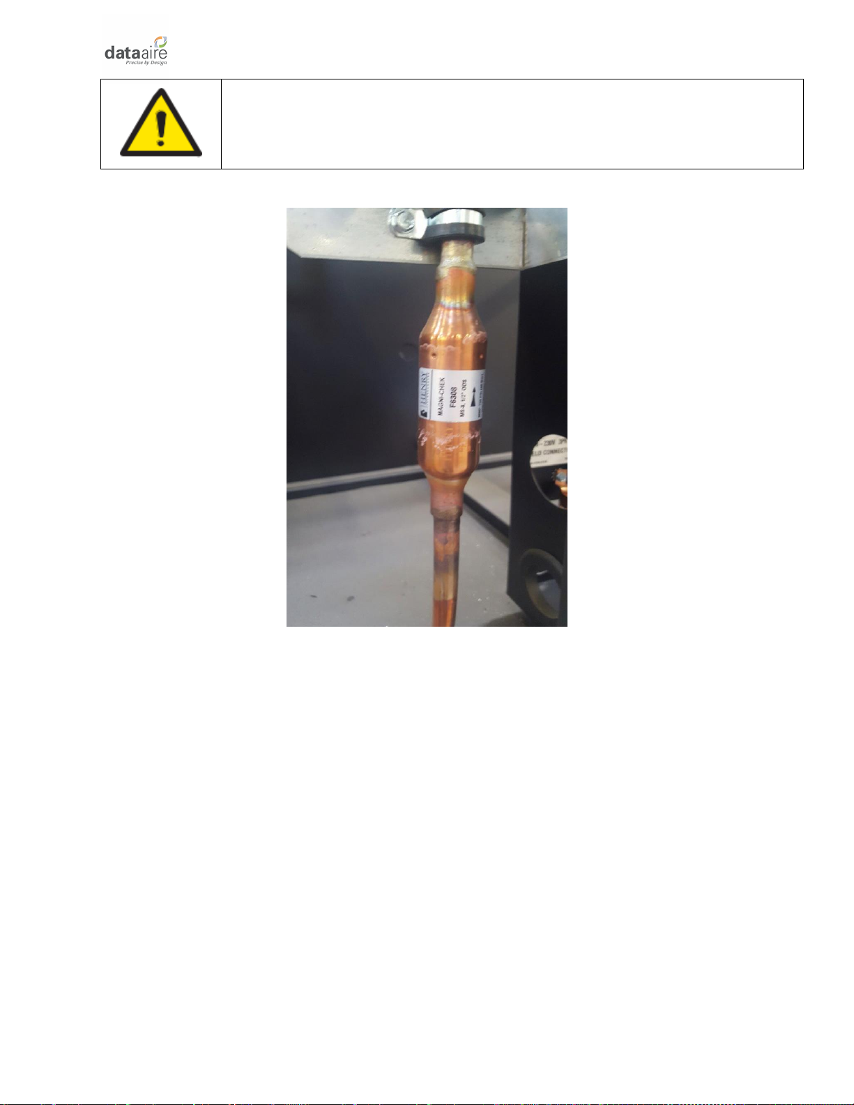
For air-cooled units built after April 2017, the discharge check valves are already installed inside the
evaporator section and do not need to be installed external to the unit. For units built before this date,
the check valves must be field supplied and installed externally to the evaporator section. If there is
doubt as to whether the check valve is already installed in the unit, look for it on the hot gas line close
to the exit point of the unit (see example picture below). The externally installed check valve should be
placed from six (6) to ten (10) feet (1.8 to 3.1 m) from the compressor.
20
NOTICE: Picture of the check valve is only intended to show an example of a
common check valve installation. It may not represent your specific unit,
check valve size, location or orientation.
Figure 3 Typical Discharge Check Valve
The check valve will prevent flow from the condenser to the compressor during the off cycle.
The evaporator section ships with a nitrogen holding charge. Do not vent the evaporator until all
refrigerant piping is in place, ready for connection to the evaporator and condenser. The discharge,
suction and liquid lines need to be refrigerant grade copper and in accordance with local code. All
refrigeration piping should be installed with high temperature brazed joints. When brazing, a supply of
nitrogen gas needs to be fed through the refrigerant lines. Be sure to open the other end of the
refrigerant line to allow the nitrogen to bleed off and not pressurize the piping. Prevailing good
refrigeration practices should be employed for piping support, leak testing, dehydration and charging
the refrigerant circuits. During the installation, the lines should be capped off and filled with dry nitrogen
at the end of each day’s work or until the system is completed and sealed.
Data Aire recommends a silver/phosphorus/copper alloy with 5 to 15% silver be used to braze the
refrigerant line sets to the indoor and outdoor units. Nitrogen needs to be flowing through the lines to
eliminate carbon deposit buildup on the inside of the joints. Carbon could contaminate the refrigerant
and restrict the metering device.
Piping must be supported within 18” (457 mm) of the inlet and outlet connections external to the unit.
Internal to the unit, the inlet connection is located on the top header of all units. The discharge outlet is
located at the bottom of the header.
Other manuals for DAMA-01
1
This manual suits for next models
3
Table of contents
Other Data Aire Accessories manuals


Popular Accessories manuals by other brands


Orno
Orno OPERA AC manual

Comelit
Comelit SD01A quick start guide

American Standard
American Standard Acrylux 38" x 38" Corner Shower Base... Product features

Flexit
Flexit CI 77 Installation and operation instructions

PCB Piezotronics
PCB Piezotronics 208A12 Installation and operating manual

Sennheiser
Sennheiser KB 55 Bedienungsanleitung


