Data Aire GHFC Series Installation guide

1 •Air-Cooled Condenser Manual

AIR-COOLED FLUID COOLER
2 •Air-Cooled Condenser Manual
CONGRATULATIONS ON THE SELECTION OF A DATA AIRE PRECISION
ENVIRONMENTAL CONTROL SYSTEM. PROPER INSTALLATION, OPERATION AND
MAINTENANCE OF THIS EQUIPMENT WILL ENSURE YEARS OF OPTIMAL
PERFORMANCE.
Safety Alert Symbols and Words for Hazard Alerting Safety
DANGER indicates a hazardous situation which, if not
avoided, will result in serious injury or death.
WARNING indicates a hazardous situation which, if not
avoided, could result in serious injury or death.
CAUTION indicates a hazardous situation which, if not
avoided, could result in minor or moderate injury.
NOTICE indicates information considered important but may
have potential hazard for personal injury or property damage.
NOTICE: This Installation, Operation and Maintenance Manual (IOM)
is intended to assist trained service personnel by providing necessary
guidelines for this equipment. Service to Data Aire units should be
done by qualified individuals with an adequate background in areas
such as HVAC, electrical, plumbing and electronics, as applicable.
WARNING: Service performed by unauthorized or unqualified
technicians may void manufacturers’ warranties and could result in
property damage and/or personal injury.
WARNING: Special care should be given to those
areas where these symbols appear.
Data Aire, Inc. reserves the right to make design and component changes for the
purpose of product improvement or to withdraw any design without notice.

AIR-COOLED FLUID COOLER
3 •Air-Cooled Condenser Manual
TABLE OF CONTENTS
1.0 INTRODUCTION ..........................................................................................................5
1.1 Model Identification................................................................................................................................5
1.2 Inspection ..............................................................................................................................................5
1.3 Paperwork .............................................................................................................................................6
1.4 Storage..................................................................................................................................................6
1.5 Locating the Remote Heat Exchanger ..................................................................................................8
1.6 Leg Assembly ......................................................................................................................................10
1.7 Rigging ................................................................................................................................................10
1.8 Installation ...........................................................................................................................................11
2.0 PIPING........................................................................................................................13
3.0 GLYCOL SYSTEMS ...................................................................................................15
3.1 Glycol Concentration ...........................................................................................................................15
3.1Preparing a Glycol System..................................................................................................................15
3.2 GHFC/DAFC Fluid Cooler Internal Volume .........................................................................................16
3.3 Copper Piping Internal Volume ...........................................................................................................16
3.5 Freezing Point of Aqueous Solutions ..................................................................................................17
3.6 Mixing Glycol and Water .....................................................................................................................17
4.0 ELECTRICAL CONNECTIONS..................................................................................18
4.1 General Electrical Field Wiring Guidelines..........................................................................................18
4.2 Electrical Service.................................................................................................................................19
4.3 Nameplate Ratings..............................................................................................................................19
4.4 Grounding............................................................................................................................................20
4.5 Voltage Tolerance ...............................................................................................................................20
4.6 Phase ..................................................................................................................................................21
4.7 Remote Heat Exchanger Auxiliary Control Wiring ..............................................................................21
4.8 Disconnect Switch (Optional) ..............................................................................................................22
4.9 Wiring Diagrams..................................................................................................................................23
5.0 CONTROLS................................................................................................................24
5.1 Electronically Commutated (EC) Axial Fan Motors (Optional).............................................................24
5.2 Permanent-SplitCapacitor (PSC) Type Fan Motors............................................................................24
5.3 Energy Saver Cooling (Optional).........................................................................................................24
6.0 WARRANTY...............................................................................................................26
7.0 MAINTENANCE .........................................................................................................26
7.1 Service vs. Maintenance .....................................................................................................................26
7.2 Cabinet ................................................................................................................................................27
7.3 Coils.....................................................................................................................................................28

AIR-COOLED FLUID COOLER
4 •Air-Cooled Condenser Manual
7.4 Electrical Control Enclosure ................................................................................................................29
7.5 Fuse Replacement ..............................................................................................................................30
7.6 Axial Fans with Electronically Commutated Motor..............................................................................30
7.7 Preventive Maintenance......................................................................................................................33
7.8 Maintenance Functions .......................................................................................................................34
8.0 FREQUENTLY ASKED QUESTIONS (FAQ).............................................................35
9.0 CONTACT DATA AIRE..............................................................................................37
10.0 REMOTE THERMOSTAT BULB MOUNTING INSTRUCTIONS............................38
10.1 TYPICAL SENSING BULB INSTALLATION.......................................................................................38
10.2 NOTES ................................................................................................................................................38

AIR-COOLED FLUID COOLER
5 •Air-Cooled Condenser Manual
1.0 INTRODUCTION
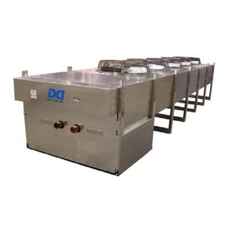
The Data Aire Air-Cooled Fluid Cooler (Dry Cooler) is low-profile, direct-drive axial or
propeller fan-type heat exchanger suitable for mounting outdoors. The Fluid Cooler
(FC) is a completely closed loop industrial grade dry type fluid cooler available in a wide
range of sizes for process cooling applications. A closed-circuit design conserves both water
and energy and is environmentally friendly. The GHFC/DAFC Series effectively eliminates
scaling and corrosion, water treatment and sewage costs.
All fluid coolers are provided with electrical control enclosure with unit mounted controls
(including pump contactor and overloads). Constructed with an aluminum cabinet and a
copper-tube aluminum fin coil, the unit is quiet and corrosion resistant. The fluid cooler is
quickly and easily installed, because all internal wiring is completed at the factory with only
electrical connections to be made at the job site. All electrical connections and controls are
enclosed in an integral weatherproof electrical control section of the fluid cooler. The AC
motors are thermally protected direct drive type. Fan cycling is controlled by ambient
thermostats or electronic temperature controller on dry coolers with more than one fan.
1.1 Model Identification
1.2 Inspection
This Data Aire unit has been factory run tested and has passed a comprehensive inspection
prior to packaging and shipment ensuring it arrives in excellent condition. However, shipping
damage can occur and a visual inspection of the outer crating immediately upon delivery
should be performed.
NOTICE: Note any external damage or other transportation damage on the
freight carrier’s forms. Inspect the unit itself for internal damage. A claim
should be filed with the shipping company if the equipment is damaged or
incomplete.
XX FC -nnn X X
│ │ │ │ │
gForce EC Fans - GH │
PSC Fans - DA
────
┘ │ │ │ │ Voltage
│ │ │ │ 2 - 208/230 VAC
│ │ │ └
────
3 - 380/400 VAC
│ │ │ 4 - 460 VAC
Fluid Cooler - FC
────
────
┘ │ │
│ │ Phase
Nominal kW (GHSeries)
────
────
────
────
┘ └
────
────
1 - Single phase (DASeries Only)
Nominal Tons (DASeries) 3 - Three phase
Remote Fluid Cooler Model Numbering

AIR-COOLED FLUID COOLER
6 •Air-Cooled Condenser Manual
Loose items such as remote-controller display panel, disconnect switch handles or other items
are packed inside the unit. Refer to the yellow shipping tag located on the door for details.
Before unpacking the fluid cooler, verify that the labeled equipment matches the bill of lading.
NOTICE: Freight damage claims are the responsibility of the purchaser.
Action to recover losses should be filed immediately. Please notify factory
personnel of any claims.
1.3 Paperwork
Each Data Aire unit ships with paperwork which includes a start-up sheet that should be
completed during installation. Return the completed Start-Up Sheets to the factory to validate
the warranty. Also included in the paperwork is a warranty/information packet that provides
important wiring diagrams, specific component literature, warranty registration cards and other
valuable paperwork including a copy of this Installation, Operation and Maintenance Manual
(IOM). A yellow tag is attached to the outside panel of the unit to indicate articles that may
have been packaged and shipped loose within the unit that are not factory mounted.
NOTICE: It is the responsibility of the installing contractor to returnthe Start-
Up Sheet and Warranty Registration card to Data Aire for proper activation
of the unit warranty. Failure to do so may cause delays and in some cases
void the warranty.
WARNING: This equipment may contain substance that has been
deemed harmful to public health and the environment. Venting of
refrigerants to the atmosphere is illegal. Refrigerant recovery devices
must be used when installing and/or servicing these types of products.
1.4 Storage
Data Aire equipment comes ready for immediate installation. However, in some instances, it
may be necessary to store the equipment for a period. If you must store the equipment, it
should be done in a dry area, out of the weather, protected from freezing temperatures,
protected from damage by other equipment in storage, or transportation equipment. Avoid
stacking and frequent relocation.
If equipment is stored for longer than 30 days special precautions must be taken to avoid coil
damage. All coils should be charged and sealed with a low pressure (less the 25 PSIG (172
kPa)) inert gas, such nitrogen. This prevents contaminants from entering the coils. When the
seal is broken at installation, the rush of escaping gas verifies the coil is still leak free. If coils
are not charged and sealed, condensation mixes with air pollutants forming a weak acid and
over time can cause pinhole leaks to develop in coil tubes.
Short-term storage is considered 60 days or less from shipment date. Long-term storage is
considered any period beyond 60 days from date of shipment. It is mandatory that a detailed

AIR-COOLED FLUID COOLER
7 •Air-Cooled Condenser Manual
record be maintained during this long-term period, such as, but not limited to proper sealing
of the cabinet, rotation of the fans, blowers and bearings, and protection of all motors from
moisture. Check the fan rotation monthly, the fan and motor should be rotated several times
to replenish the bearing surfaces with fresh grease as needed and to prevent flat spots of the
fan shaft. The fan impeller should be left at approximately 180° from that of the previous month
to prevent the belts from taking a set position.
It will be the responsibility of the customer to submit a monthly log sheet showing the condition
of the unit and noting any discrepancies. A copy of the log sheet should be sent to Data Aire.
Failure to perform the long-term storage requirements may void the warranty.
1.4.1 Suggested Storage Room Conditions
This information is provided for reference and guidance purposes only.
•Dry bulb temperature range: 65°F to 85°F (18.3F to 29.4F).
•Effects of high temperatures may dry out components or may damage electrical
components, if applicable.
•Effects of low temperatures may cause freezing damage to coil, compressor,
system components, electrical components, etc. Freezing temperatures must be
avoided, if applicable.
•Humidity range: 25 to 50% RH.
•High humidity may cause damage to insulation and electrical components. Storage
in moist air, above 50%, should be avoided. High humidity may cause rust on metal
components such as sheave, pulley, blower housing, cabinet parts, supports, etc.
•Low Humidity may cause brittle conditions to components within the unit. At low
humidity, problems of brittleness or electrical static might arise for the equipment.
•Level with floor.
•Units with compressor maximum tilt angle is 30° (compressor not running) but
recommend the unit be set level for 24 hours prior to final installation.
•Store at non-condensing temperature and humidity conditions.
1.4.2 General Storage Considerations
•All equipment shall be stored for safety of occupants. Per OSHA codes and codes
applicable to your installation.
•Maintain clearance from working space and traffic areas.
•Components sealed in plastic shrink-wrap are not exempt from this requirement.
Moisture will collect inside the plastic, resulting in corrosion of the cabinet, the
electronic components and or other water sensitive components.
•Provide proper fire protection per local and national codes.
•Protect from all water or fluid sources. Equipment should be protected from possible
water damage, such as from leaks, fire-sprinkler discharge, and flooding.
•The storage space should be filtered to remove dust, cleansed of gaseous
contaminants, if present, and controlled to the desired relative humidity and
temperature.

AIR-COOLED FLUID COOLER
8 •Air-Cooled Condenser Manual
•Isolate this equipment from pressure testing of water, steam, gas and air piping.
•Isolate this equipment from temporary building power.
•The unit must also be protected from damage to the exterior of the cabinet or coil
connections by construction vehicles and personnel.
•Isolate from vibration sources.
•Isolate from direct sun light.
•Isolate from storage of hazardous materials and substances.
•Refrigerant coils have been evacuated and pre-charged with slight nitrogen holding
charge. DO NOT damage or disturb these coils and connections.
•Water coils must have all inlet and outlet connections capped or closed tight to
prevent foreign materials and liquids from gaining entrance during the storage
period.
•When equipment is installed after storage, caution should be taken to inspect and
replace damaged components, if required.
•All moving parts should be hand tested to ensure they are free and clear prior to
start-up.
1.5 Locating the Remote Heat Exchanger
Locating remote air-cooled fluid coolers (i.e., heat exchangers) installation:
•In secure areas offering maximum security.
•Where service is easily accessible.
•Areas where public access is available should be avoided.
•Install in an area with adequate airflow. Remote heat exchangers should be located
in clean areas free from debris or foreign matter that could clog the coil surface.
Avoid areas with loose dirt or other blowing matter which might clog the coil.
•Avoid areas that contribute to ice and snow accumulation. Thefluid coolermayneed
to be elevated to ensure it is above the snow line in certain regions of the country.
•Avoid areas of hot air or fume exhaust. Remote heat exchangers should not be
located near steam vents.
•Remote heat exchangers located in areas which are exposed to ocean salt air,
industrial or agricultural areas with air pollution should be specified with an optional
coil coating.
•Heat exchangers must be installed on a level surface.
•Mount the heat exchangers with vertical airflow unless the heat exchanger is a
special horizontal airflow unit.
•Remote heat exchangers should not be closer than 36 inches (914 mm) from a wall
or any obstruction. with proper clearance on all other sides.
•With proper clearance on all sides, two (2) units can be placed side by side.
Additional units must be placed at least 48 inches (1219 mm) apart. See Figure 1
Typical Fluid cooler Spacing.

AIR-COOLED FLUID COOLER
9 •Air-Cooled Condenser Manual
Figure 1 Typical Fluid cooler Spacing
•Avoid air recirculation conditions that could be caused by walls, screening, etc.
•Do not connect any ductwork to the coil inlet or fan outlet.
•Keep fan discharge away from building air intakes.
•The remote heat exchanger must be located in an area that will ensure airflow into
and out of the heat exchanger plus adequate service access clearance. Short
circuiting of the airflow or the intake of warmer air from another unit will seriously
degrade the performance of the air-cooled heat exchanger.
•Do not locate the heat exchanger in a location that is bordered by tall obstructions
(i.e. higher than 10 feet (3 meters)) on more than two sides. Do not install heat
exchangers in a pit. See Figure 1 or minimum clearance from obstructions and
between units.
•Noise factors should be considered when locating an air-cooled heat exchanger.
Proximity to windows, walls and surrounding structures can cause objections by the
occupants. An acoustical expert should be consulted when noise is of a concern.
•Avoid installing heat exchangers near occupied spaces, above or outside utility
spaces and corridors whenever possible in order to reduce sound transmission
and/or vibration to occupied spaces.
•Water piping should be flexible enough to prevent transmission noise or vibration
from the unit. Isolation hangers should be used to prevent the transmission of
vibration on all suspended (from the building) water lines.
•Dual wide heat exchangers are field mounted side by side (see drawing 600-000-
881).
•Consult the Data Aire Service department before installing heat exchangers outside
of these conditions.

AIR-COOLED FLUID COOLER
10 •Air-Cooled Condenser Manual
1.6 Leg Assembly
The legs must be unbolted from their collapsedshipping position and extended prior to placing
the unit on its pad. Each leg extends down approximately 18 inches (457 mm) and reattaches
using the same bolts.
NOTICE: Failure to extend the legs will result in poor air distribution
over the cooling coil resulting in significant capacity reduction and
system failure.
Concrete pads are often used to provide support for the heat exchanger when set on the
ground. Bolt holes in the bottom of each leg can be used to anchor the unit. Units mounted
on the roof should be placed on or suitable curbs or railsdesigned to distribute the unit weight.
Standard practices and in accordance with local codes should be followed in either instance.
1.7 Rigging
Outdoor heat exchangers should be moved to their mounting location (typically rooftop) using
a crane or forklift. Each fan section has heavy gage, steel leg supports with lifting holes at the
top of the legs.
Do not lift with a choke sling around the unit or coil. Spreader bars are recommended for lifting
multiple fan units (See Figure 2). Under no circumstances should the coil headers or piping
be used for lifting the unit. Ideally, the unit should be kept in its shipping crate until it is ready
to be set in place.
WARNING: Use care when moving this equipment. Improper
handling could result in injury. Proper care should be taken when
uncrating the unit. The packaging has wrapping bands with sharp
edges that are under tension, crating has staples and splinters.
Proper protective equipment should be worn by qualified personnel.

AIR-COOLED FLUID COOLER
11 •Air-Cooled Condenser Manual
Figure 2 Typical Lifting Method
1.8 Installation
NOTICE: There is no intent on the part of Data Aire, Inc. to define local
codes or statutes which may supersede common trade practices. The
manufacturer assumes no responsibility for their interpretation. Consult
local building codes and the National Electrical Code (NEC) for special
installation requirements.
1.8.1 Installation Checklist
WARNING: When preparing the equipment, proper care should be
taken when uncrating the unit. The packaging has wrapping bands
with sharp edges that are under tension, crating has staples and
splinters. Proper Protective Equipment (PPE) should be worn by
qualified personnel.
● Remove the metal strapping bands
● Remove the wooden crating
● Remove the protective plastic covering
WARNING: Before removing from the packaging inspect the unit for
any damage. Report any damage to the carrier and file a damage
claim.

AIR-COOLED FLUID COOLER
12 •Air-Cooled Condenser Manual
As a precaution, review the following checklist to ensure proper operation. Failure to meet the
following conditions could result in voiding the warranty:
•Only qualified and experienced service technicians should perform installation and
maintenance on this product.
•Check for any damage.
•Check all wiring connections.
•Equipment damage and personal injury can result from improper piping installation,
leak checking and improper handling.
•This equipment is designed to operate properly and produce rated capacities when
installed in accordance with industry standards.
•System piping must be installed following industry standards for good piping practices.
•System must be thoroughly leak checked before initial charging
•System power supply must meet Voltage Tolerance (see section 4.5).
•All controls and safety devices properly connected per wiring diagram.
•Factory installed wiring must not be changed without written factory approval.
•Additionally, the fluid piping must comply with local code.
•Additionally, the fluid piping must comply with local code.
•It is recommended that the installing contractor provide shutoff valves and unions to
permit easy access to parts for either repair or replacement.
•After piping is completed all joints (and connections) should be leak tested.

AIR-COOLED FLUID COOLER
13 •Air-Cooled Condenser Manual
2.0 PIPING
Tightly drawn Teflon tape should be used on threaded pipe joints where needed.
Glycol piping requires no insulation except when fluid temperature will be below ambient dew
point temperatures. Fluid coolers typically produce around 70°F (21.1°C) or higher fluid
temperatures.
Proper piping practices should be employed to ensure air can be vented from the system
when filling or adding fluid. Air vents are required at all high points in the piping in order to
bleed air when filling the system.
Gates valves (field provided by others) are recommended to be installed on both sides of the
pump to prevent loss of fluid during repair or replacement. Shut-off valves (field provided by
others) are also recommended at the fluid cooler in the event the evaporator is to be moved
or maintenance is required for the coolant system.
Piping must be supported within 18 inches (457 mm) of the inlet and outlet connections.
WARNING: With any fluid connection there is risk of leakage. Fluid
leakage could result in property damage. Fluid leakage can result
from improper installation and/or practices.

AIR-COOLED FLUID COOLER
14 •Air-Cooled Condenser Manual
Figure 3 Typical Fluid Cooler System
NOTES:
1. - - - - - - - Indicates Field Piping - Provided by the installing contractor.
2. The expansion tank is a required component of a proper system installation. The tank
can be provided by Data Aire as an option.
3. All water/glycol field piping must be designed and installed in accordance with ASHRAE
standards and local codes.
4. Centrifugal pumps and components are optional. A flow switch is required with dual
pump application.
5. Variable pump flow control or a bypass system are the responsibility of the installing
contractor when a 2-way valve is specified in the evaporator section of a water/glycol
cooled unit.

AIR-COOLED FLUID COOLER
15 •Air-Cooled Condenser Manual
3.0 GLYCOL SYSTEMS
3.1 Glycol Concentration
The system must be filled with water and the appropriate amount of antifreeze (ethylene or
propylene glycol) making an aqueous solution which protects against winter freezing. In
order to achieve the approximate glycol concentration, it is necessaryto know the total system
volume. The total system volume consists of the fluid cooler volume, the evaporator unit
volume and the volume of the interconnecting piping.
The following tables can be used for arriving at an approximate system volume. After
installation, the glycolpercentage should bechecked. Theglycolpercentagemustbechecked
after installation and at regular intervals to ensure against freeze protection. Hydrometers are
required to insure an accurate reading.
WARNING: Fluid coolers operating without glycol mixture and
operating in ambient temperatures less than 32°F (0°C) must have
adequate freeze protection.
NOTICE: Risk of improper handling of glycol products can cause
environmental damage. Before using any glycol products, review the
latest manufacturer's Material Safety Data Sheets and ensure that you
can use the product safely. The installing contractor must read,
understand and comply with the information on the product packaging
and in the current Material Safety Data Sheets.
This information also must be available to anyone responsible for
operation, maintenance and repair of the fluid cooler and related
equipment. Because government regulations and use conditions are
subject to change, it is the end user responsibility to determine that this
information is appropriate and suitable under current, applicable laws and
regulations.
3.1 Preparing a Glycol System
Ensure the fluid system is clean of any dirt, oil, or metal filings that could contaminate the
cooling system piping and prevent contamination of the fresh glycol solution and fouling of the
fluid cooler piping. Flush the system thoroughly using a mild cleaning solution or high-quality
water and then completely drain before charging with glycol.
Cleaning a new system is just as important as cleaning an old one. New systems can be
coated with oil ora protective film. Dirt and scale arealso common. Any residual contaminants
could adversely affect the heat-transfer stability and performance of your system. In most
cases, special cleaners are needed to remove scale, rust, and hydrocarbon foulants from
pipes, manifolds, and passages.
Follow the manufacturer’s instructions when using any glycol system cleaning products.

AIR-COOLED FLUID COOLER
16 •Air-Cooled Condenser Manual
3.2 GHFC/DAFC Fluid Cooler Internal Volume
Model
Volume, Gallons
Model
Volume, Gallons
GHFC 021/ DAFC 06
2.5
GHFC 130/ DAFC 37
13.0
GHFC 025/ DAFC 07
3.4
GHFC 141/ DAFC 40
16.3
GHFC 032/ DAFC 09
4.2
GHFC 155/ DAFC 44
16.2
GHFC 039/ DAFC 11
3.3
GHFC 176/ DAFC 50
20.3
GHFC 053/ DAFC 15
4.9
GHFC 201/ DAFC 57
24.6
GHFC 060/ DAFC 17
6.6
GHFC 215/ DAFC 61
19.6
GHFC 074/ DAFC 21
7.4
GHFC 264/ DAFC 75
26.0
GHFC 084/ DAFC 24
9.8
GHFC 281/ DAFC 80
32.6
GHFC 099/ DAFC 28
12.3
GHFC 310/ DAFC 88
32.4
GHFC 106/ DAFC 30
9.8
GHFC 352/ DAFC 100
40.6
3.3 Copper Piping Internal Volume
Pipe Diameter (Inches)
Volume per 100 Feet of
Pipe (Gallons)
5/8”
1.2
3/4”
1.8
7/8”
2.5
1-1/8”
4.3
1-5/8”
9.2
2-1/8”
16.1
2-5/8”
24.8
3-1/8
35.4
4-1/8
62.2

AIR-COOLED FLUID COOLER
17 •Air-Cooled Condenser Manual
3.5 Freezing Point of Aqueous Solutions
ETHYLENE GLYCOL
% by VOLUME
FREEZING POINT
F (C)
PROPYLENE GLYCOL
% by VOLUME
FREEZING POINT
F (C)
0
32 (0)
0
32 (0)
10
20 (-6.6)
10
27 (-2.8)
20
15 (-9.4)
20
18 (-8.8)
30
4 (-15.6)
30
8 (-13.3)
40
-13 (-25)
40
-6 (-21.1)
50
-33 (-36.1)
50
-26 (-32.2)
3.6 Mixing Glycol and Water
If possible, it is recommended to purchase the antifreeze solution already pre-mixed by the
manufacturer. If this is not the case, always pre-mix the glycol and water prior to adding to the
system. The chemical reaction between the two will release oxygen. Oxygen is extremely
undesirable in a closed loop system.
NOTICE: Risk of using the wrong type of glycol. Can cause piping
damage, coolant fluid leaks, and catastrophic and expensive building and
equipment damage.
Do not use automotive antifreeze as it contains chemicals that can
damage the piping system.
Typical inhibited formula ethylene glycol and propylene glycol are
supplied with corrosion inhibitors and do not contain a silicone anti-leak
formula. Commercial ethylene glycol and propylene glycol, when pure,
are generally less corrosive to the common metals of construction than
water itself. Aqueous solutions of these glycols, however, assume the
corrosivity of the water from which they are prepared and may become
increasingly corrosive with use when not properly inhibited.

AIR-COOLED FLUID COOLER
18 •Air-Cooled Condenser Manual
4.0 ELECTRICAL CONNECTIONS
DANGER: Arc flash and electric shock hazard. Risk of electrical
shock could result in injury or death. Disconnect local and remote
facility power source before working within this equipment. Access
should be limited to authorized personnel.
Wear appropriate Personal Protective Equipment per NFPA 70E
before working within unit.
Use voltmeter to make sure facility electrical power is turned OFF
before making any electrical connections. Failure to comply can
cause injury or death.
The Customer must provide earth ground to unit, per NEC, CEC
and local codes, as applicable. Before proceeding with installation,
read all instructions, verify that all the parts are included and check
the nameplate to be sure the voltage matches available utility
power.
WARNING: Data Aire equipment must be connected by a licensed
and qualified electrician. Risk of electrical shock could result in injury
or death. Disconnect all remote electrical facility power prior to
working on the unit. All wiring must conform to local and national
electrical code requirements.
Seal openings around piping and electrical connection to prevent air
leakage. Failure to do so could reduce the unit’s cooling performance.
NOTICE: Single or dual Disconnect Switch are optional. The disconnect
switch when turned OFF will de-energize the high voltage.
CAUTION: Check the wiring connections in the unit control panel to
ensure they are tight. Screw terminals may become loose in transit.
Tightening of wiring connections is the responsibility of the installing
contractor. Remove all packing and shipping materials from the unit
before installation.
4.1 General Electrical Field Wiring Guidelines
•Do not run low voltage or control wires in same conduit, raceway, or chase as high
voltage wiring.
•Upon arrival of the unit inspect all wiring and electrical components for damage,

AIR-COOLED FLUID COOLER
19 •Air-Cooled Condenser Manual
either visible or concealed before installation.
•Use correctly sized copper wire only and verify that all electrical connections are
tight before turning power “ON”.
•Check all electrical connections periodically and tighten as necessary.
•All field supplied signal cable (if applicable) shall have the following specifications
(Control wires only):
a. Conductors—AWG stranded copper
b. Twisted pair (minimum eight twists per foot)
c. Braided shield or foil shield
d. UL approved temperature rated to 105°C
e. UL approved voltage rated to 600V
f. UV-resistant, oil resistant and moisture-resistant if not provided in conduit.
g. Plenum rated (As required by national or local codes.)
•All field supplied wires shall have the following guidelines:
a. Conductors - stranded copper and sized per circuit ampacity under NEC
b. UL approved temperature rated to 105°C
c. UL approved voltage rated to 600V
d. UV-resistant, oil resistant and moisture-resistant if not provided in conduit.
e. Wire Ampacity: Please refer to NEC for other wire sizes
4.2 Electrical Service
Before proceeding with the electrical connections, make certain that the volts, hertz, and
phase correspond to that specified on the unit electrical nameplate. Check to be sure the
electrical service provided by the utility company is enough to handle the additional load
imposed by this equipment.
Remote fluid coolers will typically require one power source. Glycol systems with fluid coolers
and loose pump(s) typically require one power source for the fluid cooler and will require one
additional source for a single pump or two additional sources for dual pumps. Systems where
the pump(s) are mounted and piped integral to the fluid cooler will usually require a single
power source.
4.3 Nameplate Ratings
Refer to the unit electrical nameplate for equipment electrical requirements. The unit
nameplate is located inside the electrical control enclosure door. The nameplate includes
Minimum Circuit Ampacity (MCA) also known as wire sizing amps which indicates the
minimum required wire gauge. The Maximum Overcurrent Protection (MOP) device amps
indicates the maximum circuit breaker or fuse size required to protect the system. Max. Fuse
or Max. CKT. BKR. indicates the maximum breaker or fuse size and this information is used
to size the appropriate fuses or a Heating, Air Conditioning, and Refrigeration (HACR) type
circuit breaker. Other protection devices are not allowed based upon the product UL listing.
The facility main distribution panel which provides electrical service to the Data Aire equipment

AIR-COOLED FLUID COOLER
20 •Air-Cooled Condenser Manual
must be provided with a manual fused disconnect switch or HACR type circuit breaker per
local and national electrical codes.
4.4 Grounding
The equipment frame must have an uninterrupted true earth ground. The facility earth ground
wire of adequate size must be connected to the ground lug provided inside the main electrical
box.
4.5 Voltage Tolerance
4.5.1 Three Phase Voltage Tolerance
The supply voltage to the unit for three phase operation must be within a voltage tolerance
per table below. The maximum allowable voltage phase to phase imbalance must not exceed
3%. Voltage imbalance causes high amperage over one or several phases, which in turn leads
to overheating and possible damage. The local utility company should be contacted for
correction of improper line voltage. Deviation from ratings can cause premature failures and
possibly void unit warranty. For three-phase units, only three power wires and an earth ground
are required. A neutral is not required at the unit input connections.
Three Phase Voltage
Voltage
Tolerance
208-230
-5% to +10%
460
±10%
575-600
±10%
4.5.2 Single-Phase Voltage Tolerance
The supply voltage to the unit for single phase operation must have a tolerance per table
below. The local utility company should be contacted for correction of improper line voltage.
Deviation from ratings can cause premature failures and possibly void unit warranty. A neutral
is not required at the unit input connections.
Single Phase Voltage
Voltage
Tolerance
208-230
-5% to +10%
This manual suits for next models
41
Table of contents
Other Data Aire Accessories manuals
Popular Accessories manuals by other brands
PCB Piezotronics
PCB Piezotronics 2508-03A Installation and operating manual
Viking
Viking PB-1 Technical practice
Girard Products
Girard Products VISION INSTALLATION SERVICE AND REPAIR
Orno
Orno OR-AE-1310 quick start guide
Amana
Amana EXTENDED WALL SLEEVE installation instructions

Advance acoustic
Advance acoustic SUCCESS 5 manual
