Data Aire gForce DX Instruction manual

2
CONGRATULATIONS ON THE SELECTION OF A
DATA
AIRE PRECISION
ENVIRONMENTAL CONTROL SYSTEM. PROPER INSTALLATION,
OPERATION
AND
MAINTENANCE OF THIS EQUIPMENT WILL ENSURE YEARS OF OPTIMAL
PERFORMANCE.
There are separate Installation, Operation and Maintenance and User Manuals for other
components of your Data Aire precision environmental cooling system including dap4
micro-processor controller and condenser/condensing unit and fluid cooler.
NOTE: This manual is intended to assist trained service personnel by
providing necessary guidelines for this equipment. Service to Data Aire
units should be done by qualified individuals with an adequate
background in areas such as HVAC, electrical, plumbing and
electronics, as applicable.
WARNING: Service performed by unauthorized or unqualified
technicians may void manufacturers’ warranties and could result in
property damage and/or personal injury
Safety Alert Symbols and Words for Hazard Alerting Safety
DANGER: Indicates a hazardous situation which, if not avoided, will
result in serious injury or death
WARNING: Indicates a hazardous
situation
which, if not avoided,
could
result
in serious injury or
de
ath.
CAUTION: Indicates a hazardous si
tuation
which, if not avoided,
could result
in
minor or moderate
injur
y
.
NOTICE: Indicates
information
considered
important
but may have
potential hazard for personal injury or property damage.
Data Aire, Inc. reserves the right to make design changes for the purpose
of product improvement or to withdraw any design without notice.
3
TABLE OF CONTENTS
1.0 INTRODUCTION...........................................................................................................................................7
Product Information................................................................................................................................7
Model Identification ................................................................................................................................7
Inspection...............................................................................................................................................8
Paperwork ..............................................................................................................................................8
Storage...................................................................................................................................................8
Suggested Reference Storage Room Conditions ..................................................................................9
General Storage Considerations............................................................................................................9
Registered Trademarks –Copy Rights –References Section.............................................................10
2.0 INSTALLATION............................................................................................................................................11
Recommended Tools for Installation....................................................................................................12
Pre-Installation .....................................................................................................................................12
Installation must be planned so that:....................................................................................................12
Room Considerations...........................................................................................................................13
Equipment Handling and Rigging.........................................................................................................14
Door and Rear Panel Removal .....................................................................................................14
Rear Panel....................................................................................................................................15
Moving Unit into Final Location.....................................................................................................15
Rigging.................................................................................................................................................16
Locating the Unit ..................................................................................................................................17
Downflow Units.....................................................................................................................................17
Upflow Units .........................................................................................................................................18
Piping ...................................................................................................................................................19
Air Cooled Unit Piping ..........................................................................................................................20
Discharge Lines....................................................................................................................................20
Liquid Lines..........................................................................................................................................22
Recommended Line Sizing, Air Cooled Units ......................................................................................23
Hot Gas Lines............................................................................................................................23
Liquid Lines ...............................................................................................................................24
Suction Lines.............................................................................................................................25
Connection Sizes, Air Cooled Units .....................................................................................................26
Field Piping, Remote Condenser Above Evaporator............................................................................27
Field Piping, Remote Condenser Below Evaporator............................................................................28
Refrigerant Piping Protection ...............................................................................................................29
Water/Glycol Cooled Unit Piping..........................................................................................................30
Field Piping, Water/Glycol System.......................................................................................................31
Connection Sizes, Water/Glycol Cooled Units .....................................................................................32
Connection Sizes, Fluid Coolers (Dry Coolers)....................................................................................32
Auxiliary Chilled Water/Energy Saver Coil Piping ................................................................................32
Condensate Drain Piping .....................................................................................................................32
Humidifier Piping..................................................................................................................................33
Steam Generator Humidifier......................................................................................................33
Dry Steam Humidifier ...........................................................................................................................34
Leak Testing.........................................................................................................................................34
4
Electrical Installation.............................................................................................................................34
Commissioning Information..................................................................................................................35
3.0 ELECTRICAL CONNECTIONS...................................................................................................................36
General Electrical Field Wiring Guidelines...........................................................................................37
Electrical Service..................................................................................................................................38
Nameplate Ratings...............................................................................................................................38
Grounding.............................................................................................................................................38
Voltage Tolerance................................................................................................................................38
Three Phase Voltage Tolerance ...................................................................................................38
Single-Phase Voltage Tolerance...................................................................................................39
Heat Exchanger Auxiliary Control Wiring .............................................................................................39
Remote Shutdown................................................................................................................................40
Remote Alarm Contacts.......................................................................................................................40
dap4 Controller.....................................................................................................................................41
Disconnect Switch (Optional) ...............................................................................................................41
How to Open the Electrical Enclosure Panel........................................................................................41
Condensate Pumps (Optional).............................................................................................................42
Condensate Probe ...............................................................................................................................42
Water Sensing Cable (Optional)...........................................................................................................43
Remote Temperature and Humidity Sensors (Optional).......................................................................43
Manual Override Switch Board.............................................................................................................43
Plug Fan Current Sensing Switch ........................................................................................................44
Wiring Diagrams...................................................................................................................................44
Electronic Expansion Valve Optional ...................................................................................................44
Electrical Connection to EEV.....................................................................................................44
4.0 INSTALLATION OF REMOTE OUTDOOR HEAT EXCHANGER ................................................................45
5.0 CHARGING.................................................................................................................................................46
Charging/Installation Work Procedures................................................................................................46
Triple Evacuation and Dehydration Procedure.....................................................................................46
Tools Needed................................................................................................................................47
First Stage Evacuation..................................................................................................................47
Second Stage Evacuation.............................................................................................................48
Third Stage Evacuation.................................................................................................................48
Final Evacuation Stage.................................................................................................................49
General Pre-Charging Guidelines ........................................................................................................49
Voltage Phase Check...........................................................................................................................50
Evaporator Power Phase Check...................................................................................................50
Fixed Speed Scroll Compressor Phase Check.............................................................................50
Heat Exchanger Phase Check......................................................................................................51
Line Set Charge Calculations...............................................................................................................51
Component Functional Test.................................................................................................................52
CHARGING PROCEDURES................................................................................................................52
Refrigerant Handling.....................................................................................................................52
Air Cooled System Charging.........................................................................................................52

5
Charging the Fixed Speed Compressor........................................................................................54
Additional Oil.................................................................................................................................56
Flooded System Charging (Systems with Low Ambient Receiver Package)................................56
Receiver Installation......................................................................................................................58
Charge Fixed Speed Compressor.................................................................................................59
Water/Glycol-Cooled System Charging ........................................................................................60
Refrigerant Handling ............................................................................................................................61
Important Refrigeration Components ...................................................................................................62
Expansion Valves..........................................................................................................................62
High Pressure Cutout Switch ........................................................................................................62
Low Pressure Cutout Switch .........................................................................................................63
Liquid Line Solenoid Valve (Optional)............................................................................................63
6.0 GLYCOL SYSTEMS....................................................................................................................................64
Glycol Concentration............................................................................................................................64
Internal (Fluid) Volume –Up and Downflow Evaporators.....................................................................64
Brazed-Plate Condensers.............................................................................................................64
Internal (Fluid) Volume –Fluid Coolers.................................................................................................66
Fluid Cooler Information................................................................................................................66
7.0 CONTROLS.................................................................................................................................................67
dap4™ Microprocessor Control Panel..................................................................................................67
Remote Heat Exchangers....................................................................................................................67
Electronic Expansion Valve Drive (EDV) ..............................................................................................67
Setup Using Display Panel Guide .................................................................................................67
Configuration Menu.......................................................................................................................68
Regulation Menu ...........................................................................................................................70
How to Manually Open and Close an (EEV)..................................................................................70
Multiple EEV Configuration ...........................................................................................................71
8.0 REGULAR MAINTENANCE ITEMS............................................................................................................73
Air Filters ..............................................................................................................................................73
Fuses....................................................................................................................................................73
Electric Reheat.....................................................................................................................................73
Humidifier.............................................................................................................................................74
Humidifier Canisters......................................................................................................................74
Refrigerant Filter Drier..........................................................................................................................74
Plenum (Plug) Fans..............................................................................................................................74
Electronically Commutated Motors................................................................................................74
EC Motor Testing..........................................................................................................................75
9.0 MAINTENANCE/INSPECTION CHECKLIST...............................................................................................77
10.0Frequently Asked Questions –FAQ............................................................................................................80
Electrical FAQ Section .........................................................................................................................80
Mechanical FAQ Section......................................................................................................................81
11.0CONTACT DATA AIRE...............................................................................................................................83

6
TABLE OF FIGURES
Figure 1 Typical Upper Spring-Loaded Hinge................................................................................................14
Figure 2 Upper Hole for Spring-Loaded Hinge ..............................................................................................15
Figure 3 Lower Fixed Pin Hinge.....................................................................................................................15
Figure 4 Example of Lifting Method ...............................................................................................................16
Figure 5 Typical Return & Discharge Air Distribution.....................................................................................18
Figure 6 Typical Check Valve ........................................................................................................................21
Figure 7 Typical Remote Condenser Above Evaporator Installation .............................................................27
Figure 8 Typical Remote Condenser Below Evaporator................................................................................28
Figure 9 Typical Water/Glycol System...........................................................................................................31
Figure 10 Typical Remote Heat Exchanger Interconnection Points...............................................................40
Figure 11 Typical Indoor Evaporator Interconnection Points.........................................................................40
Figure 12 Manual Override Switch Board......................................................................................................43
Figure 13 EEV with Electrical Mating Connector ...........................................................................................45
Figure 14 Typical Low Ambient Receiver Package........................................................................................58
Figure 15 Example Remote EPO Switch Connection....................................................................................81

7
1.0 INTRODUCTION
Product Information
The Data Aire gForce GF environmental control, direct expansion, dual circuit Computer
Room Air Conditioner (CRAC) equipment provides a high sensible cooling, is self-contained,
factory assembled, piped, wired, and factory tested prior to shipment. These units include an
enclosure/cabinet assembly, fan section, filter section, cooling coils, controls, and
interconnecting piping internal to unit.
The Data Aire CRAC unit provides cooling, reheat, humidification, dehumidification and air
filtration. The unit is provided with a Data Aire dap4™ microprocessor controller for precision
control. The unit must be operated in a conditioned space within the operating envelope
ASHRAE recommends for data centers. Operating outside this envelope can alter the
operating performance and decrease equipment reliability. Return air to the unit must be no
cooler than the ASHRAE recommendation for proper unit operation. Operating below this can
alter the operating performance and decrease equipment reliability. Refer to ASHRAE’s
publication, “Thermal Guidelines for Data Processing Environments.”
Model Identification
GF XX-XXX X X - XXX
│ │ │ │ │ │ │
Model Series │ │ │ │ │ │ │
GF - gForce Dual Circuit
────
┘ │ │ │ │ │ │ Auxiliary Coils
│ │ │ │ │ └ ES - EnergySaver
Type of Cooling │ │ │ │ │ ACW - AuxilaryChilled Water
A - Air Cooled │ │ │ │ │
W - Water Cooled
────
────
┘ │ │ │ │ Voltage
G - Glycol Cooled │ │ │ └
────
────
2 - 208/230 VAC
│ │ │ 4 - 460 VAC
Configuration │ │ │ 3 - 380/400V - 50Hz
Downflow
────
────
────
┘ │ │
Upflow │ │ Phase
│ └
────
────
3 - Three phase
Model/Capacity in kW │
021 kW │
028 kW │
035 kW
────
────
────
────
────
┘
046 kW
056 kW
070 kW
091 kW
106 kW
gForce GF Model Number
8
Inspection
This Data Aire CRAC unit has been factory run-tested and has gone through a comprehensive
inspection prior to its packaging and shipment to ensure that it arrives in excellent condition.
However, ship- ping damage can occur and a visual inspection of the outer crating immediately
upon delivery should be performed. Upon arrival of the unit and before unpacking it, verify that
the labeled equipment matches the bill of lading.
Loose items such as remote-control panels, disconnect switch handles, and spare air filters
are packed inside the unit. Refer to the yellow shipping tag located on the unit door for details.
NOTICE: Any external damage or transportation damage on the freight
carrier’s forms. Inspect the unit itself for internal damage. A claim should be
filed with the shipping company if the equipment is damaged or incomplete.
NOTICE: Freight damage claims are the responsibility of the purchaser.
Action to recover losses should be filed immediately. Please notify factory
personnel of any claims.
Paperwork
Each Data Aire CRAC unit ships with a start-up sheet that should be completed during
installation. Also included in the paperwork is a warranty/information packet that provides
important wiring diagrams, specific component literature, warranty registration cards and other
valuable paperwork, including a copy of this Installation, Operation, and Maintenance manual.
A yellow tag is attached to the outside decorative door to indicate articles that may have been
packaged and shipped loose within the unit cabinet. Typically this would be jackstands,
condensate pumps and other loose components that are not factory mounted.
WARNING: It is the responsibility of the installing contractor to return
the start- up sheet and warranty registration card to Data Aire for proper
activation of the unit warranty. Failure to do so may cause delays and
some cases void the warranty
Storage
Short-term storage is considered 60 days or less from shipment date. Long-term storage is
considered any period beyond 60 days from date of shipment. It is mandatory that a detailed
record be maintained during this long-term period, such as, but not limited to: proper sealing of
the cabinet, rotation of the blowers and bearings, and protection of all motors from moisture.
Check the fan rotation monthly, the fan and motor should be rotated several times to replenish
the bearing surfaces with fresh grease as needed and to prevent flat spots of the fan shaft.
The fan impeller should be left at approximately 180° from that of the previous month to
prevent the belts from taking a set position.
It will be the responsibility of the customer to submit a monthly log sheet showing the condition

9
of the unit and noting any discrepancies. A copy of the log sheet should be sent to Data Aire.
Failure to perform the long-term storage requirements may void the warranty.
Suggested Reference Storage Room Conditions
•Dry bulb temperature range: 65°F to 85°F.
•Effects of high temperatures may dry out components or may damage electrical
components.
•Effects of low temperatures may cause freezing damage to coil, compressor, system
components, electrical components, etc. Freezing temperatures must be avoided.
•Humidity range: 25 to 50% RH.
•High humidity may cause damage to insulation and electrical components. Storage in
moist air, above 50%, should be avoided. High humidity may cause rust on metal
components such as sheave, pulley, blower housing, cabinet parts, supports, etc.
•Low Humidity may cause brittle conditions to components within the unit. At low
humidity, problems of brittleness or electrical static might arise for the equipment.
•Level with floor.
•Units with compressor maximum tilt angle is 30° (compressor not running) but
recommend the unit be set level for 24 hours prior to final installation.
•Store at non-condensing temperature and humidity conditions.
General Storage Considerations
•All equipment shall be stored for safety of occupants. Per OSHA codes and codes
applicable to your installation.
•Maintain clearance from working space and traffic areas.
•Our indoor products are not designed or intended to be stored outdoors or exposed to
outdoor conditions.
•Components sealed in plastic shrink-wrap are not exempt from this requirement.
Moisture will collect inside the plastic, resulting in corrosion of the cabinet, the electronic
components and or other water sensitive components.
•Provide proper fire protection per local and national codes.
•Protect from all water or fluid sources. Equipment should be protected from possible
water damage, such as from leaks, fire-sprinkler discharge, and flooding.
•The storage space should be filtered to remove dust, cleansed of gaseous
contaminants, if present, and controlled to the desired relative humidity and
temperature.
•Isolate this equipment from pressure testing of water, steam, gas and air piping.
•Isolate this equipment from temporary building power.
•The unit must also be protected from damage to the exterior of the cabinet or coil
connections by construction vehicles and personnel.
•Isolate from vibration sources.
•Isolate from direct sun light.
•Isolate from storage of hazardous materials and substances.
•Refrigerant coils have been evacuated and pre-charged with slight nitrogen holding
10
charge. DO NOT damage or disturb these coils and connections.
•Water coils must have all inlet and outlet connections capped or closed tight to prevent
foreign materials and liquids from gaining entrance during the storage period.
When equipment is installed after storage, caution should be taken to inspect and replace, if
required, any components that may have deteriorated during storage. All moving parts, such
as fans and motors, should be hand tested to ensure that they are free and clear prior to start-
up.
Registered Trademarks –Copy Rights –References Section
NOTICE: Data Aire Inc. Trademarks Disclaimer: All names, logos, brand,
materials and other Registered Trademarks, Trademarks, or Copy Rights
seen featured or referred to within documents or our website are explicitly
the sole property of their respective and rightful trademark holders or owners.
This disclaimer shall not be construed or manipulated from hereafter. Said
trademarks or copy rights are only used to directly or indirectly familiarize,
reference, identify and describe the services.
11
2.0 INSTALLATION
NOTICE: There is no intent on the part of Data Aire, Inc. to define local codes
or statutes which may supersede common trade practices. The manufacturer
assumes no responsibility for their interpretation. Consult local building codes
and National Electrical Code (NEC) for special installation requirements.
During installation, operation, maintenance or service, individuals may be exposed to certain
components or conditions including, but not limited to: refrigerants, oils, and materials under
pressure, rotating components, and both high and low voltage. Each of these items has the
potential, if misused or handled improperly, to cause bodily injury or death. It is the obligation
and responsibility of operating/service personnel to identify and recognize these inherent
hazards, protect themselves, and proceed safely in completing their tasks. Failure to comply
with any of these requirements could result in serious damage to the equipment and the
property in which it is situated, as well as severe personal injury or death to themselves and
people at the site.
This document is intended for use by owner-authorized operating/service personnel. It is
expected that this individual possesses independent training that will enable them to perform
their assigned tasks properly and safely. It is essential that, prior to performing any task on this
equipment, this individual shall have read and understood this document and any referenced
materials. This individual shall also be familiar with and comply with all applicable
governmental standards and regulations pertaining to the task in question.
This manual contains important safety instructions that should be followed during the
installation and maintenance of Data Aire equipment. Read this manual thoroughly before
attempting to install or operate this unit.
Only qualified personnel should move, install or service this equipment. Adhere to all warnings,
cautions and installation, operating and safety instructions on the unit and in this manual.
Follow all operating and user instructions.
WARNING: Risk of handling heavy and lengthy parts, risk of top-heavy
unit falling over, risk of sharp edges, splinters and exposed fasteners;
can cause personal injury and equipment damage. Cabinet doors and
panels can weigh more than 35lb. (15.9kg) therefore follow relevant
OSHA lifting recommendations and consider using a two-person lift for
safe and comfortable removal and installation of cabinet doors and
panels.
Only properly trained and qualified personnel wearing appropriate safety
headgear, gloves and shoes should attempt to remove or install cabinet
doors and panels.

12
Recommended Tools for Installation
•Wrenches –Common sizes
•Flat tip and Phillip screwdrivers –Common sizes
•Wiring tools
•Brazing tools
•Multimeter
•Pressure gauges –Sized for design pressure
•Electric hand tools
•Equipment handing
•Safety items
•Level
Pre-Installation
The unit you have received is very special. It is specifically designed for indoor Computer
Room cooling applications. This unit is designed and intended to be installed indoors unless
otherwise noted on the equipment serial name plate. Compare the data on the nameplate of
the air-conditioning unit and other modules with the packing list and the order documents.
During the design of the data center, consider should be given for ease of entry for the
equipment, floor loading factors, ceiling loading factors and accessibility to piping and wiring.
Before installing unit, determine whether any building alterations are required to move the unit
into the space intended, run piping, wiring and ductwork. Carefully follow all unit dimensional
drawings and refer to the submittal package and engineering dimensional drawings of
individual units for proper clearances.
If possible, transport the Data Aire unit with a forklift or pallet jacks. If using a forklift or pallet
jack, make sure that the forks (if adjustable) are spread to the widest allowable distance that
will fit under the skid. Ensure the fork length is suitable for the unit length. Keep tines of the
forklift level and at a height suitable to fit below the skid and/or unit to prevent exterior and/or
underside damage. When moving the packaged Data Aire unit with a forklift, lift the unit no
higher than 6" (152 mm) off the ground. The unit is to be pulled by the forklift. Personnel who
are not directly involved in moving the unit must be kept 20' (5 m) or farther from the lift point of
the unit.
Measure the unit and doorway heights and refer to the installation plans to verify clearances
prior to moving the unit.
Installation must be planned so that:
•Damage to building sections, including room wall insulation, is minimal.
•Components are located correctly for function and adequate air flow configuration.
•Pipe runs and electrical runs are as short as feasibly possible.
•Confirm configuration and options for the unit to be installed are to design
specifications.
•The unit may be too tall to fit through a doorway while on the skid. Measure the unit and
doorway heights and follow the installation plans to verify clearances prior to moving the
13
unit.
•Allow enough space around the unit for removing the access panels and various parts
of the unit. A minimum clearance equal to the width of the unit is suggested on one side
of the unit for removing the coil or fan assembly. Add dimension of pipe chase, ducts,
control and electrical panels, etc. to minimum clearances. Allow additional clearance as
required by local and national codes.
•It is also necessary to consider access requirements for safe operation and
maintenance of the unit, and power and control panels. Local health and safety
regulations, or practical considerations for service replacement of large components
(such as coil), may require larger clearances.
•Clearance dimensions provided elsewhere are necessary to maintain proper service
access. If clearances given are not maintained, service the unit will be more difficult or
impossible maintain.
WARNING: Risk of improper moving, can cause equipment damage,
injury or death.
WARNING: Before removing from the packaging inspect the unit for any
damage. Report any damage to the carrier and file a damage claim.
Room Considerations
Precision air conditioning equipment is designed to control spaces within close tolerances of
temperature and humidity. However, the room must be built with a proper vapor barrier. A film
of polyethylene is often used on walls and ceilings. Walls and floors must also be painted with
vapor-seal paint. Failure to provide a vapor barrier can compromise space conditions.
Introduction of outside air into the space should be minimized. Outside air in excess of 5% of
the total circulated air volume can have a significant effect on the overall space conditions and
result in poor space control.
•Install the units as close as possible to the largest heat load.
•For floor units, verify that the floor is level, solid and enough to support the unit. The
equipment must be level to operate properly and prevent damage to the internal
components. Shimming and/or grouting may be necessary. This is to ensure the unit
base is on a perfectly flat plane.
•It is recommended that support is structurally engineered to prevent flexing, sagging or
twisting. Do not obstruct door operation, filter access, piping, electrical control panel or
control connections.
•Avoid the transfer of vibrations to the mounting materials which may cause audible
noise.
14
Equipment Handling and Rigging
WARNING: Only properly trained personnel wearing appropriate safety
head- gear, gloves, shoes and glasses should attempt to move the unit,
lift it, remove packaging or prepare the unit for installation.
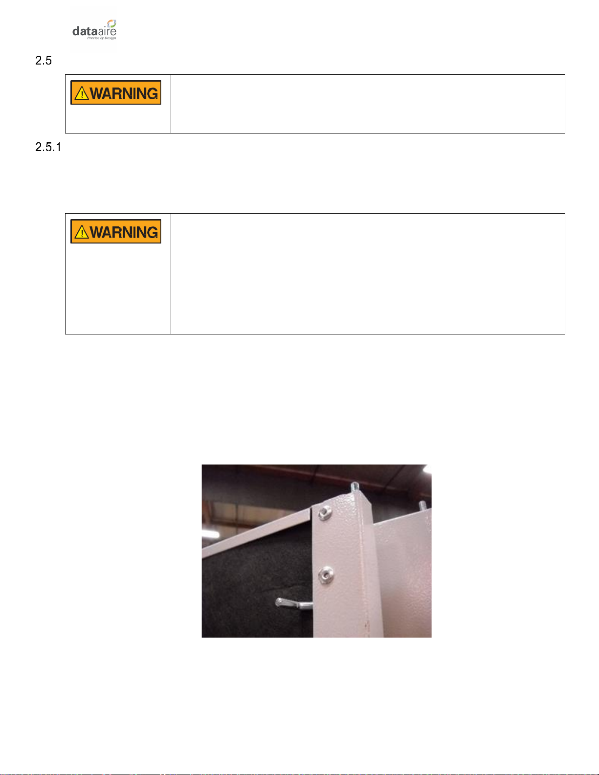
Door and Rear Panel Removal
Removal of the decorative doors is easily accomplished and may be done when moving
equipment. The door hinge is spring loaded and slides down using the catch, for easy removal
of the doors. Door hinges allow the door to be lift off.
WARNING: When releasing the spring-loaded upped door hinge, be
prepared for the weight of the door. Risk of handling doors can cause
personal injury and equipment damage. Follow relevant OSHA lifting
recommendations and consider using a two-person lift for safe and
comfortable removal and installation of doors. Only properly trained and
qualified personnel wearing appropriate safety headgear, gloves and
shoes should attempt to remove or install doors.
Unlock and open the door by using a flat blade screwdriver or other tool to turn the door latch
90 degrees to unlock the door. Most doors on larger floor mounted units will have a door latch
at the top and bottom of each door. Unplug the dap display connection cables, if needed.
Pull down on the spring-loaded catch to disengage the top of the door, then lift the door up and
off the fixed bottom hinge pin. When re-installing doors, remember to reconnect the dap4
display interface connection cable, if needed.
Figure 1 Typical Upper Spring-Loaded Hinge

15
Figure 2 Upper Hole for Spring-Loaded Hinge
Figure 3 Lower Fixed Pin Hinge
Rear Panel
Remove screws from rear panel to remove rear panel.
Moving Unit into Final Location
Move the unit in its upright position to the installation site using a forklift or pallet jack. It is
recommended that the unit be protected from damage to the decorative doors during any
storage or moving.
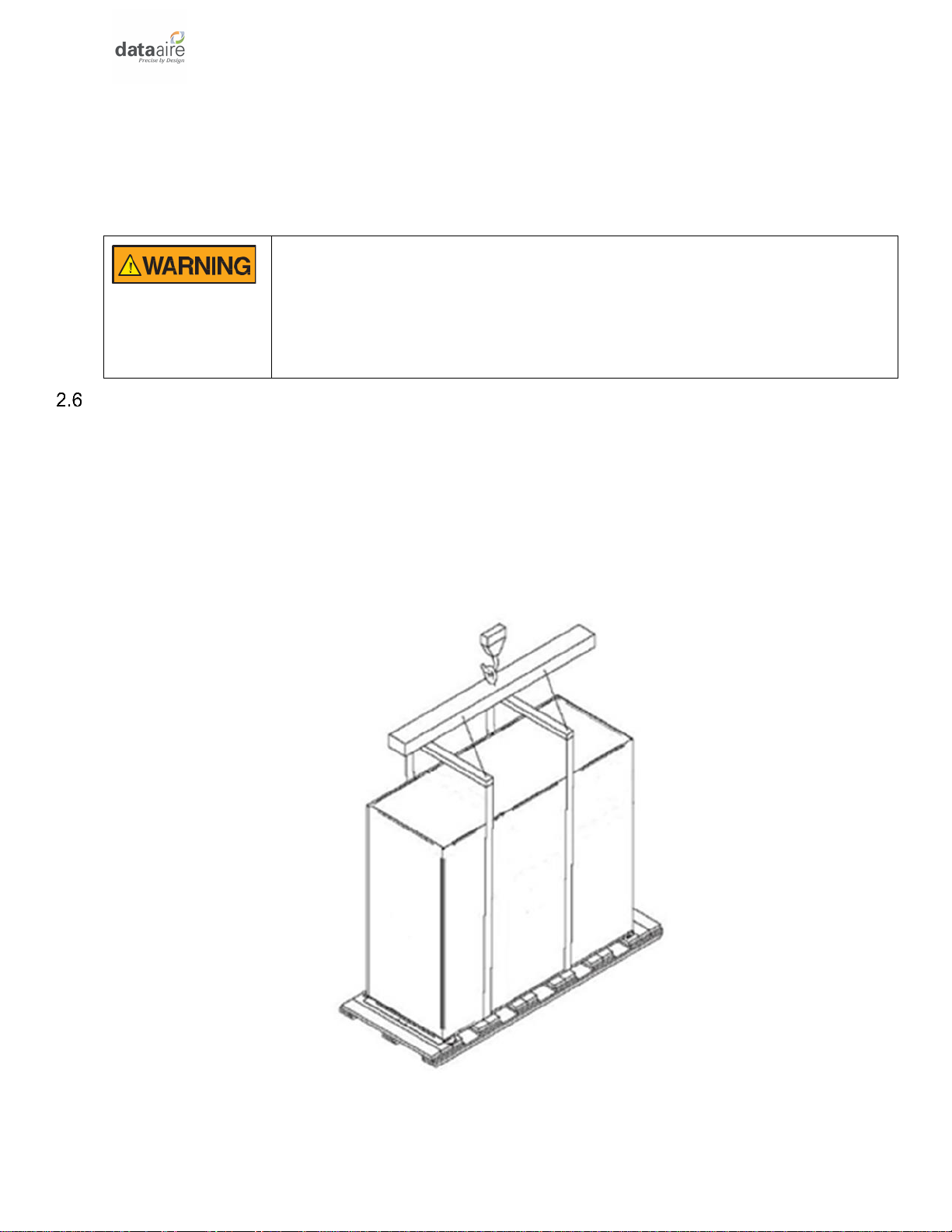
The shipping skid should be left in place if the unit is being moved with a forklift. If the unit is
being lifted, use spreader bars to prevent damage to the doors and panels. The unit shipping
skid as 3/4” holes in the shipping skid to which casters with 3/4” stems can be attached. This
allows easy movement down halls, into elevators and through doorways. Improper lifting or
moving of equipment may result in damage to decorative doors, panels or frame members.
When rigging, make sure all wiring and tube connections are protected to prevent any
damage.
Keep tines of the forklift level and at a height suitable to fit below the skid and/or unit to prevent
exterior and/or underside damage. Make sure the forks are spread to their widest allowable
width for proper balance. Do not lift the unit any higher than 4 inches (100mm) off the ground.
16
If necessary, to lift higher than the suggested 4 inches (100mm), exercise great care to ensure
proper handling of the unit.
Personnel not involved with the lifting of the unit should keep a safe distance from the unit.
The unit may be too tall to fit through a doorway while on the skid. Measure the unit and
doorway heights and refer to the installation plans to verify clearances prior to moving the unit.
WARNING: Use care when moving. Improper handling could result in
injury. Proper care should be taken when uncrating the unit. The packaging
has wrap- ping bands with sharp edges that are under tension, crating
has staples and splinters. Proper protective equipment should be worn
by qualified personnel.
Rigging
Move the unit in its upright position to the installation site. It is recommended that the unit be
protected from damage to the decorative doors during any storage or moving. Removal of the
decorative doors is easily accomplished and may be done without moving the equipment.
The shipping skid should be left in place if the unit is being moved with a forklift. If the unit is
being lifted, use spreader bars to prevent damage to the doors and panels.
Figure 4 Example of Lifting Method
The unit has 3/4” (19mm) holes in the shipping skid to which casters with 3/4” (19mm) stems
can be attached. This allows easy movement down halls, into elevators and through doorways.
If clearance is a problem the casters may be inserted directly into the bottom of the 1” (25mm)
17
tubular steel corner posts at the bottom of the unit.
WARNING: Improper lifting or moving of the equipment may result in
damage to the decorative doors, panels or frame members.
Locating the Unit
Verify that the floor is level, solid and appropriate construction to support the unit. When
installing the unit, enough space must be allowed for airflow clearance, wiring, plumbing and
service access. It is recommended that each side and front have a clearance of at least 36”
(914mm) to allow the doors to swing open and for servicing the unit.
The doors on some sides may not require as much service clearance. Refer to the specific unit
component breakdown drawings for assistance. Rear clearance is not required, but 1” to 2” (25
to 50mm) of clearance is suggested.
For the best air distribution, the unit should be centered against the longest wall, distributing
the cold air as close to heat load as possible, unless the unit is ducted. The unit should not be
placed near any corner of the room or at the end of a long, narrow room. Install the units as
close as possible to the largest heat load. Multiple units should be evenly spaced, as far apart
as possible. It is recommended to install an under-floor water detection system.
NOTICE: Condensation formation and frequent humidifier flushing are
normal functions of this equipment. Proper drain connections must be
made to ensure proper removal. Unit will require water connections for
condensate removal and possibly for humidifier makeup water, chilled
water and/or hot water. Installation of units above equipment that could
sustain water damage should be avoided.
Downflow Units
Downflow units will typically sit on an elevated flooring system known as a raised floor. The
unit dis- charges air downward which pressurizes the raised floor and channels upward
through perforated floor tiles. Location and quantity of perforated tiles will dictate proper air
distribution. If the raised floor is strong enough to support the unit and local codes permit, the
unit can be placed directly on top with cutouts made for the discharge openings.
Verify that the raised floor has been properly sized for the unit’s airflow and the room is free of
airflow restrictions. Perforated floor tiles in the raised floor should ensure minimal pressure
loss. The raised floor must provide a minimum of 12” (305 mm) clearance. Ensure that there is
adequate clearance above the unit for service, such as replacing filters. Optional plenums are
available for downflow unit ducting.
18
Figure 5 Typical Return & Discharge Air Distribution
There may be additional support required in the form of adjustable jackstands. These are
adjustable, threaded leveling rods which support the unit in each of the corners and in the
center on longer length units. Tighten the locknuts provided with each jackstand. The base
plate can rest on the floor or on vibration pads.
Floorstands are also a way of supporting the unit. These are ordered to the height of the raised
floor with leveling rods to allow adjustment. The floorstand has lips in each corner to align with
the unit which is placed on top. It is recommended that the unit frame be bolted or screwed to
the floorstand from below. Local building codes may dictate this procedure. After installation,
the raised floor is typically built around the unit.
The raised floor serves as the distribution plenum for air on downflow units. Cables, piping,
wiring raceways, inadequate floor height and any other restrictions can inhibit proper airflow.
Care should be taken to avoid restrictions.
Verify that the raised floor has been properly sized for the unit’s airflow and the room is free of
airflow restrictions. Perforated floor tiles in the raised floor should ensure minimal pressure
loss. The raised floor must provide a minimum of 12” (305 mm) clearance. Ensure that there is
adequate clearance above the unit for service, such as replacing filters. Optional return air
plenums are available for downflow unit ducting.
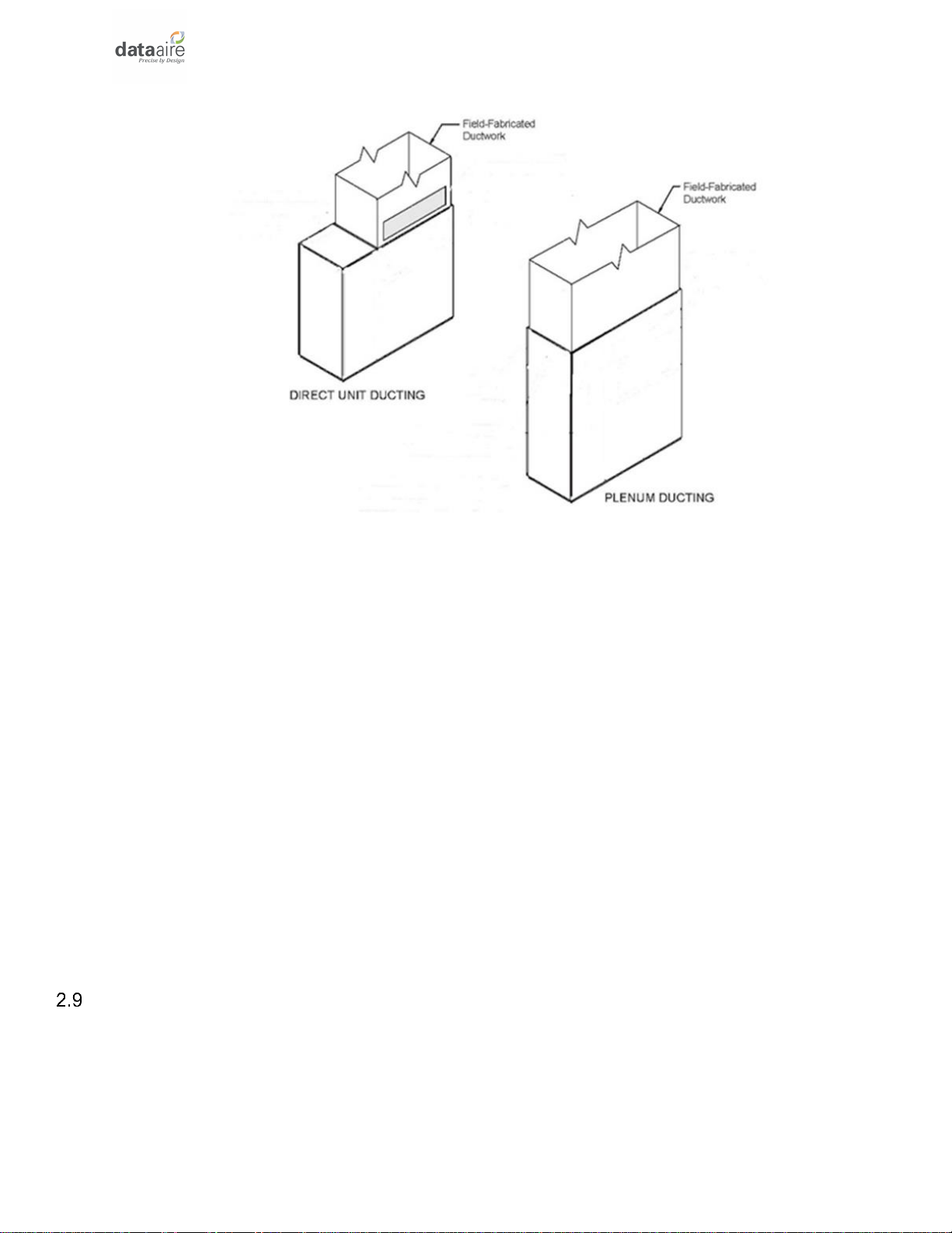
Upflow Units
Upflow units will typically be supported by vibration isolation pads and/or floorstands which
may also include leveling legs. An air discharge plenum may be factory provided which ships
loose and must be attached at the top of the unit frame. For in-room applications with supply
and return grilles, several feet of clearance must be maintained at the intake and discharge of
the unit.

19
Alternately, an air distribution plenum must be field fabricated with supply grilles to distribute
the air. If a common plenum is utilized to connect the supply air for distribution from multiple
units, it is recommended that isolation backdraft dampers be installed on the discharge end of
the unit or somewhere prior to the common plenum to prevent cold discharge air from entering
units that may be on standby. Alternatively, we offer an AireSeal option which keeps the EC
fans running at a selectable speed between 20-50% when the unit is in standby to prevent air
from entering the units from the common plenum. Units are shipped with Electronically
Commutated (EC) motors often referred to as “plug fans”. Fan speed is factory set based on
order. Fan speed can be changed in 1% increments through the Data Alarm Processor (dap4)
microprocessor controller, by several different methods. See the dap4 User Manual for details
and recommended settings.
WARNING: Do not operate upflow units without installing a plenum,
ductwork or guard over the fan opening(s) on the top surface of the
cabinet. Ductwork must be connected to the fan(s), or a plenum must be
installed on the top of the cabinet for protection from rotating blower
wheel(s) on upflow units. Risk of high-speed moving parts can cause
injury or death. Disconnect all local and remote electric power supplies
before working in the unit.
NOTE: Seal openings around piping and electrical connection to prevent air
leakage. Failure to do so could reduce the unit’s cooling performance.
Piping
•All refrigerant piping should be is Type L Air Conditioning Refrigeration (ACR) hard
drawn copper pipes. Soft copper is unacceptable.
•When brazing refrigerant lines, an inert gas should be passed through the line at low
pressure to prevent scaling and oxidation inside the tubing. Dry nitrogen is preferred. No
soldering allowed.
•Completely de-burr and clean tube end and inside surface of piping.
•Use only a suitable silver alloy on suction and liquid lines. Limit the flux to the minimum
required to prevent contamination of the joint internally. Flux only the male portion of the
connection, never the female. After brazing, remove excess flux.
•All refrigeration piping materials are subject to changes in temperature and will expand
and contract with temperature change. Installation techniques must allow for expansion
and contraction changes for piping connections, this will prevent stresses which may
buckle and rupture the copper tube piping or joints.
•Proper piping practices should be employed to ensure adequate oil return, even under
minimum load conditions with special consideration given to the size and proper slope
of the tubing coming from the evaporator. See section 2.14 Recommended Line Sizing,
Air Cooled Units for more information on line sizes.
•Tubing returns from the evaporator should be designed so as not to trap oil and to

20
prevent oil and refrigerant migration back to the compressor during compressor off
cycles.
Piping should be designed with adequate three-dimensional flexibility. It should not be in
contact with the surrounding structure, unless a proper tubing mount has been installed. This
protection proves necessary to avoid excess vibration, which can ultimately result in
connection or tube failure due to fatigue or wear from abrasion. Aside from tubing and
connection damage, excess vibration may be transmitted to the surrounding structure and
generate an unacceptable noise level within the structure as well.
When piping, use copper tubing with appropriate supporting devices (supporting saddles, etc.).
All field piping must be installed according to local codes. Avoid piping runs through noise-
sensitive areas, such as office walls and conference rooms.
Piping and to the ASHRAE Refrigeration Handbook for general, good-practice refrigeration
piping.
All piping below the raised floor must be located so that it does not restrict airflow. Plan the
piping layout under the raised floor to prevent the airflow from being blocked. When installing
piping on the subfloor, it is recommended that the pipes be mounted in a horizontal plane
rather than stacked one above the other. Whenever possible, the pipes should be run parallel
to the airflow.
Ensure that the tubing surfaces to be brazed are clean and that all burrs have been removed
from the ends of the tubes. Ensure that all loose material has been cleaned from inside the
tubing before brazing. Keep piping clean and dry, especially on units with R-410A refrigerant.
The units may be ordered with top or bottom connections.
Air Cooled Unit Piping
Air-cooled unit piping is crimped and brazed closed from the factory and contains a nitrogen
holding charge. Each installation requires field-supplied refrigerant piping to a condenser.
Refer to section 2.14 Recommended Line Sizing, Air Cooled Units for a guideline on sizing
refrigerant lines. The ultimate responsibility for line size selection is that of the installing
contractor or design engineer. Data Aire does not assume this responsibility. The chart covers
distances up to 200 equivalent feet (61 m). For installations beyond this distance, consult
ASHRAE or similar references.
NOTE: Standard piping practice must be used to ensure proper oil return
and efficient operation. The interconnecting lines to the remote air-cooled
condenser or condensing unit must be installed by a qualified refrigeration
mechanic.
Discharge Lines
Discharge lines, also called hot gas lines, should be trapped at the top (inverted) and bottom
as well as every 15 to 20 feet (4.6 to 6.1 m) of vertical rise. Discharge check valves are
required on all installations, especially those where there are long pipe runs or cold climates.
Table of contents
Other Data Aire Accessories manuals


Popular Accessories manuals by other brands


Matsui
Matsui JL4-5V-3~6 Operation manual

Omron
Omron F400 - 06-1999 Operation manual

SEBSON
SEBSON IR OUT F user manual

Hubbell
Hubbell KILLARK ACCEPTOR UGR Series INSTALLATION, OPERATION & MAINTENANCE DATA SHEET

Chamberlain
Chamberlain 915GA install guide

Milesight
Milesight LoRaWAN EM320-TH quick start guide