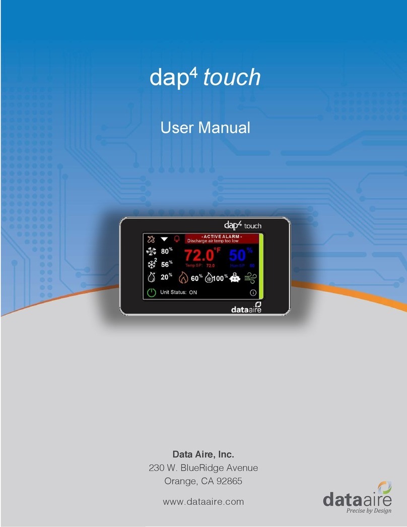
Data Aire dap4 touch User manual

2
Notice: The screens displayed in this manual are for illustration purposes
only. Most settings are shown at their default value or a setting that allows
another screen or setting to appear. These settings are not necessarily the
best for your specific application.
Data Aire, Inc. reserves the right to make design changes for the purpose of
continuous product improvement or to withdraw any design without notice.
This manual was written when dap4 controllers were shipped with:
Software Version 2.16
Earlier versions may not have some of the features indicated, while later
software versions may have additional features that are not listed.
The graphic touch screen contains its own software version which must be
equal to or higher than the controller’s software version.

3
Table of Contents
(If viewing as a pdf, press Ctrl and click section you want to access).
Introduction........................................................................................................................ 4
Optional Equipment &
Features
......................................................................................... 5
Getting Started.................................................................................................................... 6
Status Loop.......................................................................................................................... 7
MENU A –ON / OFF.......................................................................................................... 16
MENU B –SETPOINTS ....................................................................................................... 17
MENU C –CLOCK/SCHEDULER.......................................................................................... 23
MENU D –INPUT/OUTPUT ............................................................................................... 28
MENU E –HISTORICAL DATA............................................................................................ 29
MENU F –INFORMATION................................................................................................. 31
MENU G –NETWORK CONFIGURATION (Service Level) ............................................... 32
MENU H - CALIBRATE SENSORS (Service Level)............................................................. 34
MENU I –MANUAL CONTROL (Service Level)............................................................... 35
MENU J –FACTORY SETTINGS (Factory Level)............................................................... 36
MENU K –ALARMS & LIMITS (Service Level).................................................................... 62
MENU L –CONFIGURE I/O (Factory Level) .................................................................... 79
MENU M –SET ZONE CONTROL ....................................................................................... 81
Operation of Fan............................................................................................................... 89
Operation of Chilled Water Cooling.................................................................................. 91
Operation of DX Cooling ................................................................................................... 93
Operation of Reheat ......................................................................................................... 98
Operation of
De
humidifi
c
ation....................................................................................... 101
Operation of Humidifier.................................................................................................. 105
Operation of Zone Con
tr
ol.............................................................................................. 107
Operation of Airside Economizer.................................................................................... 112
Alarms............................................................................................................................. 116
Wiring Connections......................................................................................................... 129
Glossary........................................................................................................................... 132

4
Introduction
The dap4 continues the tradition of advanced electronic devices from Data Aire for
monitoring and control of computer room air conditioning units which began in 1977.
Each generation has provided more accurate monitoring and application flexibility.
Control - The dap4 offers the definite answer for precision environmental
control. The dap4 control system not only controls temperature, humidity, airflow
and cleanliness; it provides component run times, hourly duty cycles and 24-hour
temperature and humidity deviations.
Efficiency - Airside and waterside economizers are available to help conserve
power usage. Features like “Humidity Anticipation” offsets the humidity set point
to reduce excess humidification and dehumidification. Options such as variable
compressors and electronic expansion valves also contribute to energy savings.
Alarm Management -The dap4 offers extensive alarm management. An
array of alarms conditions may be enabled, and some can be set to stop
operations or completely shut down the unit. Up to 200 of the most recent alarms
are stored in an alarm log. Each alarm has temperature and humidity readings
and the date time it occurred to assist in diagnosing what caused the alarm. There
are four alarm relay contacts that can be programed to energize for any multiple
of alarm conditions.
NOTICE… Please don’t let the size of this manual overwhelm
you, as it covers many options and features of the dap4 that
may not apply to your specific application.

5
Optional Equipment & Features
Electronic Expansion Valve: The module communicates to the dap4 to drive a
stepper motor inside the expansion valve. The module controls refrigerant
superheat and optimizes the efficiency of the refrigerant circuit. It features low
superheat, high evaporation pressure (MOP), and low evaporation pressure (LOP)
protection.
Power Meter Module: The module communicates to the dap4 to allow monitoring
of voltage, amperage, wattage, VA and power consumption (kWh). It also records
daily power use trends for the last 30-day span and offers phase loss alarm
protection. The ultra-compact module measures only 3.11”tall by 4.25” long and
uses only 1.4” of DIN rail space.
Zone Control: A feature that offers multiple dap4 controls a teamwork solution.
Up to sixteen dap4 units may be arranged in the Zone Control network. Unit 1 has
menus with selectable features of:
•Minimum number of units that must always be on
•Automatic lead/lag and standby unit rotation
•Activate a standby unit due to selected alarm conditions
•Activate standby units to assist with controlling temperature or airflow
•Inhibit control functions to prevent units from conflicting operations
•Primary and secondary schedules for economical control
•Unified zone airflow control
Idap Communication Card: A network card with web-based application software
installed. It allows a standard PC to communicate with the dap4 controller. It has
an intuitive menu system that includes: System Status, Configuration, Data and
Graphs, Events and Emails and a Points Table. It can be setup to send trending
data for the previous 24-hour period allowing for review and analysis. The idap
card can be used on a stand-alone basis, in place of a BMS system. It can also
operate in conjunction with a BMS system, using BACnet, Modbus TCP/IP or
SNMP protocols.
Rack Sensor Modules: Allows up to 20 rack temperature sensors to be
connected to the dap4 to control fan speed. Sensors can be set to work
independently or arranged in groups. The rack temperature calculation can be set
to use the highest of the sensors or an average of the sensors.
Power Cap: Allows the dap4 to continue operation during short term power
interruptions. This feature is valuable where power sources are not reliable or
when power may switch to a stand-by generator.

6
Getting Started
The dap4 consists of two main components: the controller and the display panel. The
controller is located inside the electrical panel. The display panel is mounted on the
front door of the cabinet and/or mounted in a remote location. They are connected by
a special telephone type cable. (Note: If you need a longer cable, please contact the
factory, as special cables are used for long
dap4 Controller (standard size shown)

7
dap4 Color Touch Display
There are several touch sensitive areas on home screen of the display. Listed below
is how each area works when it is touched.
Access service menus shown later in this manual (requires holding 1 sec.)
Displays the next screen.
Displays the Alarm Log screen.
Touch Temp/Hum
readings to display the
Set Points screen.
LED Unit Status
White = On Blue
= Cooling Green
= E. Saver
Red = Alarm
“Power Key” turns Unit on or off.
Color red = unit is off, Green = unit is on.
Displays the system
Information Screen.
Status Loop
The first screen in this loop is the Home screen, which displays the basic status of
the unit. It contains icons that appear when a specific operation is running as
described below:
Fan On - If variable type, speed modulation is also shown.

8
Compressor On - A number will also appear next to the icon to
indicate multiple compressors are running. If variable type, speed
modulation is also shown.
Humidifier On - If variable type, humidity demand modulation is
also shown.
Dehumidification Mode Running.
Heaters On - A number will also appear next to the icon to indicate
multiple heaters are on. If SCR or Hot Water heat type, heat
modulation is also shown.
Chilled Water Cooling On –A number will also appear next to the
icon to indicate valve modulation.
Energy Saver Available –Indicates that chilled water is cold enough
to provide cooling. Also indicates if Airside economizer can provide
cooling with damper modulation shown to the right.. Both are optional
features.
CO2 Valve On –This option only available on gPOD model.

9
Status Loop (continued):
The next screen in the status loop is the Optional screen, which displays the status
of optional inputs of the unit. (Note: this screen does not appear if no optional
inputs are used).
The next screen in the status loop is the Rack Temperature Status screen, which
displays the status of all optional rack sensor. (Note: this screen does not appear if
a rack sensor module is not used). The highest or average (depending on
selection) is shown on the top line, followed by individual sensor readings.
Sensors that are in a Low Temperature alarm have a blue colored bell next to it
(like T04). Sensors that are in a High Temperature alarm have a red colored bell
next to it (like T09). Sensors T16 to T20 (if used) appear on the next Rack
Temperature screen.

10
Status Loop (continued):
The next screen in the status loop is the Zone Status screen, which displays the
status of the zone. (Note: this screen only appears on Unit 1 when the Zone
Control feature is enabled).
The next screen the Zone Units screen, which displays the status of each units in
the zone. Note: this screen only appears on Unit 1 when the Zone Control feature
is enabled.
Touch the unit icon to see specific information such as Temperature, Humidity and
Airflow. General unit status is indicated by color:
Green = Unit On Blue = Unit in Standby
Red = Unit in Alarm Gray = Unit set not to participate

11
Status Loop (continued):
The next screen in the status loop is the Power Meter Status screen. (Note: this
screen only appears when an optional power meter is installed.
The next screen in the status loop is the Variable Compressor Status screen. Note:
this screen only appears when a variable compressor is installed. The operating
envelope is indicated by the green colored polygon. The compressor’s current
status is indicated by a red dot within the envelope.

12
Status Loop (continued):
The next screen in the status loop is the Airside Economizer Status screen. Note:
this screen only appears when the Airside Economizer is enabled is installed.
Sensor readings are displayed based on the Mode setting of the airside
economizer. Any condition that disables the economizer from running is shown in
red text at the bottom of this screen.
The next screen in the status loop is the Trending screen. It displays the historical
trends of the return air temperature and humidity. Additional trends of discharge air
temperature and chilled water temperature will also appear if installed. To display
the legend information, touch the information icon located at the top right corner.
The historical time frame screen can be scrolled forward or backwards by pressing
and dragging the screen.

13
Alarm Log Screen: (Accesses by touching the Alarm icon on the main
status screen). The time and date of past alarms along with readings at the time of
the alarm can be viewed. Touch the Up or Down icon to see past alarm logs.
There will be a short delay as each log is loaded.

14
Turning the Unit On
Turn the disconnect switch to the ON position. The controller will boot up and
conduct a self-test. After approximately 20 seconds the display will become
active.
NOTE: Unless otherwise specified, the unit is shipped with the unit to start-up in
the OFF mode. This setting can be changed to start-up in the ON mode using the
“On/Off” Menu A.
The unit may be turned on (or off) by pressing the Power icon at the bottom
left corner of the main screen. The icon is green when unit is on and red
when unit is off.
Once turned on there will be a 5 to 600 second start delay indicated by “Time
before start: XXs”. If the unit does not turn on, the Unit Status line will indicate the
reason, such as an alarm condition, scheduler setting or command from a BMS.
Service Menus
Press the “Tools” key for one second to change mode of
display to access the service menus.

15
Menus
Press the middle key on left side to access the Main Menu. The first screen will
ask for a numerical password which determines the three levels of menus that will
be displayed: User, Service and Factory.
Note: The User level password is always 0000. The Service level password by
default is also 0000 and may be changed by the installer. The Factory level
password is usually set by the maintenance supervisor to protect from
unauthorized use.
After a password is entered, the Main Menu will appear with “Service” or “Factory”
level indicated at the top right of the screen. Note: These levels will expire if no key
is pressed after 10 minutes. Use the Up or Down key to move the menu of choice
to appear in the center black line. Then press Enter key to access that menu.
The USER level displays the following main menu choices:
A. On/Off
B. Setpoint
C. Clock / Scheduler
E. Historical Data
F. Information
The SERVICE level adds the following menu choices to the user level:
D. Input / Output
G. Network Configuration
H. Calibrate Sensors
I. Manual Control
K. Alarms & Limits
M. Zone Control (only shown if feature is enabled)
The FACTORY level adds the following menu choices to the service level:
J. Factory Settings
L. Configure I/O

16
Changing the Passwords
Important Notice –Service and Factory level passwords should only
be given to qualified technicians. Under normal circumstances the
Factory menus should not be changed. Please consult with Data Aire
engineering or service personnel for help using these menus.
Change the Service level and Factory level passwords following these steps:
1. Press the Menu key.
2. Enter the current Service Level or Factory Level password.
3. The Main Menu will appear. Press the Menu key
4. The password screen will appear. Press the DOWN key.
5. A Service Security screen will appear. Choose a new service level
password. Note: if the Factory level password was entered on step 2; press
the DOWN key again to be able to change the Factory level password.
Note: Be sure you write down any changes to these passwords and store in a safe
and secure location.
MENU A –ON / OFF
On
/
O
ff
U
n
i
t
S
t
a
r
t
-
up
D
e
l
a
y
:
5
s
S
t
a
r
t
-
up
M
od
e
:
O
ff
S
t
a
t
u
s
:
O
FF
by
K
E
Y
H
o
l
d
ESC
for
5
s
ec
ond
s
t
o
t
u
r
n
un
i
t
ON
or
O
FF
Start-up Delay: This is the amount of time that the control will wait before starting.
It is often used to prevent multiple units from starting at the same time, which may
cause a surge in power. Selection is from 5 to 600 seconds with a default setting of
5 seconds. A count down timer for this delay is shown on the main status screen.
Startup- Mode: This is the mode that the unit will be in when power is applied.
Selection is either On or Off with a default setting of Off. Note: When startup mode
is set to Off, the Esc key must be used in order to turn the unit on.
Status: Shows the current unit status as displayed on the main status screen.

17
MENU B –SETPOINTS
S
e
t
po
i
n
t
s
T
e
m
p
S
e
t
po
i
n
t:
72
.
0
•
T
e
m
p
D
ea
db
a
nd
:
2
.
0
•
H
ea
t
D
ea
db
a
nd
:
2
.
0
•
S
t
age
-
T
o
-
S
t
age
:
0
.
3
•
Sync Zone
T
SP
:
No
Temp Setpoint: This set point is used to control the return or discharge air
temperature (whichever is chosen for control mode in the factory settings menu).
The range of adjustment is 45 to 105°F with a default value of 72.0°F.
Cool Deadband: This is the amount temperature must rise above set point before
the first stage of cooling turns on. Range of adjustment is 1.0 to 10.0 °F with a
default value of 2.0°F.
Heat Deadband: This is the amount temperature must drop below set point
before the first stage of heating turns on. Range of adjustment is 1.0 to 10.0 °F
with a default value of 2.0°F.
Stage-To-Stage: (Only shown on multiple compressor units). This is the amount of
temperature that separates each stage of DX cooling. The range of adjustment is
0.3 to 3.0 °F with a default of 0.3 °F.
Latent Setpoint: (IRDX model only when set for discharge latent control mode in
factory settings menu). This setpoint is calculated from the temperature setpoint
and offset by the discharge air humidity. It is not adjustable.
Latent Deadband: (IRDX model only when set for discharge latent control mode
in factory settings menu). For each increase in humidity of 0.2% above this dead
band (range of adjustment is 60 to 80% with a default of 64%) will cause the latent
set point to increase by 0.1°F.
Fan Delta Temp: (IRDX model only when fan mode is set to delta in the factory
settings menu). This is the set point for fan modulation based on the difference
between the Return and discharge air temperatures. The range of adjustment is
10.0 to 40.0 °F with a default of 20.0 °F.
Sync Zone TSP: (Only shown on Unit 1 of Zone Control network). When set to
Yes (default is No), all units in the zone will use the temperature setpoint and
deadband of Unit 1.

18
MENU B –SETPOINTS continued
E
c
ono
m
i
ze
r
S
e
t
po
i
n
t
s
H
i
E
n
t
a
l
py
:
28
.
0
BT
U
E
n
t
h
a
l
py
D
B
:
0
.
5
BT
U
M
i
n
OA
T
e
m
p
SP
:
32
.
0
•
M
a
x
OA
T
e
m
p
SP
:
78
.
0
•
OAT
D
ea
db
a
nd
:
1
.
0
•
Note: This screen is only shown when the airside economizer feature is enabled in
the factory settings menu.
Hi Enthalpy: (Shown when Economizer is set to Fixed Enthalpy mode).
Setpoint for the highest outside air enthalpy can be to close the damper.
The range of adjustment is 26 –30.0 BTU with a default value of 28.0.
Enthalpy DB: (Shown when Economizer is set to an Enthalpy mode).
Fixed Enthalpy mode: This is the amount that the outside air enthalpy must
drop below the Hi Enthalpy setpoint before the damper can reopen.
Fixed Enthalpy mode: This is the amount that the outside air enthalpy must
drop below the inside air enthalpy before the damper can reopen.
The range of adjustment is 0.2 to 1.0 BTU with a default value of 0.5 BTU.
Min OA Temp SP: This is the lowest temperature that the outside air can
be before the damper is closed. The range of adjustment is 20.0 to 45.0°F,
with a default value of 32°F.
Max OA Temp SP: (Shown only in Fixed dry bulb mode) This setpoint is
based on the climate zone setting and is not user adjustable. It is the
highest temperature that the outside air can be before the damper is closed.
Range of adjustment is 65.0 to 85.0°F.
OA DB: This is how much the outside air temperature must rise above or
drop below the OA Temp SP before the damper may reopen. The range of
adjustment is 1.0 to 5.0° with a default value of 1.0°.

19
MENU B –SETPOINTS continued
R
ac
k
T
e
m
p
S
e
t
po
i
n
t
s
T
e
m
p
S
e
t
po
i
n
t:
72
.
0
•
T
e
m
p
D
ea
db
a
nd
:
2
.
0
•
Note: This screen is only shown when the fan is set to modulate to rack
temperature in factory settings menu.
Temp Setpoint: This fan temperature set point is used to control the fan speed
based on the Rack Air Temperature. The range of adjustment is 65 to 85 °F with a
default value of 72.0 °F.
Temp Deadband: This fan deadband is the amount that temperature must rise
above the fan speed setpoint before fan speed will begin to increase. The range of
adjustment is 1.0 to 5.0° with a default value of 2.0°.
D
e
w
po
i
n
t
S
e
t
po
i
n
t
s
Low
D
e
w
po
i
n
t
S
p
:
45
.
0
•
Low
D
e
w
po
i
n
t
D
b
:
1
.
0
•
H
i
D
e
w
po
i
n
t
S
p
:
59
.
0
•
H
i
D
e
w
po
i
n
t
D
b
:
1
.
0
•
Note: This screen is only shown when humidity control is set to “Dewpoint” in the
factory settings menu or if the Air-side Economizer feature is used.
Low Dewpoint Sp: This is the Low Dewpoint Setpoint. It sets the limit for when
humidification will begin. The range of adjustment is 30.0 to 55.0 °F with a default
value of 45.0 °F.
Low Dewpoint Db: This is the Low Dewpoint Deadband. It determines how much
above the setpoint that dewpoint must rise to end humidification. The range of
adjustment is 0.1 to 3.0 °F with a default value of 1.0 °F.
High Dewpoint Sp: This is the High Dewpoint Setpoint. It sets the limit for when

20
MENU B –SETPOINTS continued
dehumidification will begin. The range of adjustment is 50.0 to 65.0 °F with a
default value of 59.0 °F.
High Dewpoint Db: This is the High Dewpoint Deadband. It is the amount that the
dewpoint must drop below setpoint before dehumidification ends. The range of
adjustment is 1.0 to 3.0 °F with a default value of 1.0 °F.
Other manuals for dap4 touch
7
Table of contents
Other Data Aire Control System manuals

