Penn System 450 Series User manual

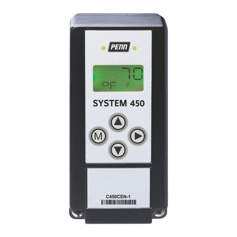
System 450 Series C450CCU Condensing Unit
Control Module Installation Guide
Description
The System 450™ Series condensing unit control module
controls space temperature, scheduled defrost cycles,
evaporator fans, and optional pump down compressor
control on medium and low temperature refrigeration
condensing units.
You can use the C450CCU-4 control module, in conjunction
with optional System 450 relay output expansion modules,
to build a variety of custom condensing unit control
systems for small and medium capacity refrigeration
applications.
The C450CCU-4 condensing unit control system provides
passive, off-cycle defrost control or active, electric heat
defrost control. Depending on the application, you can
terminate defrost cycles based on time or based on
sensed evaporator temperature. You can use a menu
option to manually initiate or terminate a defrost cycle at
any time.
You can also control single-speed or two-speed evaporator
fans, and add an optional pressure transducer for pump
down pressure control of the compressor.
Refer to the System 450 Series C450CCU Condensing
Unit Control System Technical Bulletin (LIT-12013266) for
detailed information about how to set up, operate, and
troubleshoot a System 450 condensing unit control
system.
Application
Important: Use the System 450 Series C450CCU
condensing unit control module only as an
operating control. Where failure or malfunction
of the condensing unit control module could lead
to personal injury or property damage to the
controlled equipment or other property, additional
precautions must be designed into the control
system. Incorporate and maintain other devices,
such as supervisory or alarm systems or safety or
limit controls, intended to warn of or protect against
failure or malfunction of the condensing unit control
module.
Important: Utiliser ce System 450 Series C450CCU
condensing unit control module uniquement en
tant que dispositif de contrôle de fonctionnement.
Lorsqu'une défaillance ou un dysfonctionnement
du régulateur risque de provoquer des blessures
ou d'endommager l'équipement contrôlé ou un
autre équipement, la conception du système de
contrôle doit intégrer des dispositifs de protection
supplémentaires. Veiller dans ce cas à intégrer de
façon permanente d'autres dispositifs, tels que
des systèmes de supervision ou d'alarme, ou des
dispositifs de sécurité ou de limitation, ayant une
fonction d'avertissement ou de protection en cas de
défaillance ou de dysfonctionnement du régulateur.
Installation
Figure 1: System 450 module dimensions, mm (in.)
Table 1: System 450 module dimensions, mm (in.)
Callout Description
1 35 mm DIN rail mount channel
2 12.7 mm (1/2 in.) conduit hole, nominal trade size
Mounting modules and module
assemblies
Observe the following location and mounting guidelines.
• Make sure that the mounting surface can support the
module assembly, DIN rail, mounting hardware, and
any user-supplied panel or enclosure.
• Mount the modules upright and plugged together in a
horizontal row where possible, as shown in Figure 2. It
is best practice to mount the control module on a DIN
rail.
• In direct-mount applications, mount the modules on flat
and even surfaces.
• Allow sufficient space to make connections, run wires,
and view the LCD and LEDs.
• Mount the modules in locations free of corrosive
vapors, and observe the ambient operating conditions
listed in the C450CCU condensing unit control module
technical specifications.
• Do not mount the modules on surfaces that are prone
to vibration or in locations where high-voltage relays
and motor-starters, electromagnetic emissions, or
strong radio frequency may cause interference.
24-7664-03809 Part No. Rev. C
2020-10-21
C450CCU

• Do not install the modules in airtight enclosures.
• Do not install heat generating devices in an enclosure
with the modules that may cause the ambient
temperature to exceed 66°C (150°F).
Mounting modules on DIN rail
Before you begin:
Important: When you mount a module assembly
on a DIN rail, clip the modules on to the DIN rail
individually before you slide and plug the mounted
modules together. If you clip a complete module
assembly that is already plugged together on to the
DIN rail, it can damage the 6 pin modular plugs and
void any warranties.
1. Mount the control module in a suitable location on
a section of 35 mm DIN rail that is longer than the
module assembly width. Use appropriate mounting
hardware.
2. Clip the control module on to the rail, position the
module’s upper DIN rail clips on the top rail, and
gently snap the lower clips on to the bottom of the
rail.
3. Assemble the modules in the correct order. Clip
the remaining modules to the right of the control
module on to the DIN rail and gently slide and plug
the modules together.
Note:
- If you use a C450YNN power module,
you must plug it into the control module.
Plug in any expansion modules for your
control system to the right of the power
module.
- When you power on your module
assembly, you can then set up your
control system in the control module UI
before you wire the sensors or outputs to
your assembly. If you set up the sensors
in the UI but do not connect them, an
SNF sensor failure notification displays.
Direct-mounting modules to wall
surfaces
1. Plug the modules together, remove the module
covers.
2. Place the module assembly horizontally against the
wall surface in a suitable location, and mark the
mount hole locations on the mounting surface.
3. Install appropriate screws or fasteners, and leave
the screw heads approximately one to two turns
away from flush to the mounting surface.
4. Position the assembly mounting slots over the
screw heads, and then carefully tighten the
mounting screws to secure the assembly to the
surface.
Note: If you mount the modules on an uneven
surface, use shims or washers to mount the
module assembly evenly on the surface.
Wiring
See C450CCU condensing unit control module technical
specifications for electrical ratings.
WARNING
Risk of Electric Shock
Disconnect or isolate all power supplies before making
electrical connections. More than one disconnection
or isolation may be required to completely de-energize
equipment. Contact with components carrying
hazardous voltage can cause electric shock and may
result in severe personal injury or death.
AVERTISSEMENT
Risque de décharge électrique
Débrancher ou isoler toute alimentation avant
de réaliser un branchement électrique. Plusieurs
isolations et débranchements sont peut-être
nécessaires pour -couper entièrement l'alimentation
de l'équipement. Tout contact avec des composants
conducteurs de tensions dangereuses risque
d'entraîner une décharge électrique et de provoquer
des blessures graves, voire mortelles.
Important:
• You can connect a System 450 control module
and module assembly to an internal power
source, such as a System 450 power module, or an
external power source, such as 24 VAC/VDC power
that connects to the 24 V and COM terminals on
the control module. Do not connect a control
module to both power sources simultaneously.
If you connect a control module to both internal
and external power sources, you can damage the
modules and void any warranty.
• Use copper conductors only. Make all wiring
connections in accordance with local, national, and
regional regulations.
• Do not exceed the System 450 modules' electrical
ratings. Exceeding electrical ratings can result in
permanent damage to the modules and void any
warranty.
• Run all low-voltage wiring and cables separately
from all high-voltage wiring. It is best practice to
use shielded cable for input sensor cables that
are exposed to high electromagnetic or radio
frequency noise.
• Electrostatic discharge (ESD) can damage System
450 modules. Use proper ESD precautions when
you install and service the modules to avoid
damage to System 450 modules.
System 450 Series C450CCU Condensing Unit Control Module Installation Guide2

• Do not apply power to a C450YNN power module
or the 24 VAC/VDC power source for the System
450 modules before you finish wiring and
checking all wiring connections. Short circuits or
incorrectly connected wires can result in damage
to the modules and void any warranty.
• When you connect System 450 compatible sensors
with shielded cable to a System 450 control
module, connect the cable shield drain lead to one
of the C terminals on the input sensor terminal
block. Do not connect the shield at any other
point along the cable. Isolate and insulate the
shield drain at the sensor end of the cable. If
you connect a cable shield at more than one
point, transient currents can flow through the
sensor cable shield and can cause erratic control
operation.
• Labels are included with the C450CCU controller
that describe the Expansion Module LED and Relay
operation. Place the label or labels below the LED
relay indicator or indicators on the expansion
modules.
Table 2: System 450 wiring terminals and wire sizes
Terminal block
type
Terminal
label
Terminal function Wire sizes
24 V Provides a power terminal to
connect a 24 VAC input when
you do not use the C450YNN
module.
COM Provides a 24 VAC COM
terminal to connect a 24 VAC
COM input when you do not
use a C450YNN module.
This terminal is isolated from
the C terminal by a common
mode choke internal to the
control.
5 V Provides 5 VDC power for a
low-pressure pump down
transducer.
Sn1 Connect to an A99
temperature sensor only.
Sn2 Connect to an A99
temperature sensor or binary
switch input.
Sn3 Connect a specified P499 or
P598 pressure transducer only
for low-pressure pump down
control of the compressor.
Sensor and low-
voltage supply
power terminal
block
All control
modules
C Provides low-voltage common
connections for passive
or active sensors that you
connect to the 5 V, Sn1, and
Sn2 terminals.
The terminals connect
internally.
0.08 mm2 to 1.50 mm2
28 AWG to 16 AWG
Table 2: System 450 wiring terminals and wire sizes
Terminal block
type
Terminal
label
Terminal function Wire sizes
LNC1, LNC2 Connects equipment control
circuit to the line-voltage
normally closed (LNC) contact
on the single-pole, double-
throw (SPDT) relay.
LNC2 terminals are only
on control and expansion
modules with two output
relays.
LNO1,
LNO2
Connects equipment control
circuit to the line-voltage
normally open (LNO) contact
on the SPDT relay.
LNO2 terminals are only
on control and expansion
modules with two output
relays.
Line-voltage
output relay
terminal blocks
Control and
expansion
modules with
relay output
LC1, LC2 You must connect line power
to the line-voltage common
(LC) on the SPDT relay so that
the control module can switch
line voltage between the LNO
or LNC terminals to energize
connected equipment control
circuits.
LC2 terminals are only on
control and expansion
modules with two output
relays.
0.08 mm2 to 2.50 mm2
28 AWG to 14 AWG
240 VAC Left terminal is for one 240
VAC supply power lead.
No label on
the middle
terminal
Middle terminal is the
common connection for either
the 120 VAC or 240 VAC supply
power lead.
Line-voltage
supply power
terminal block
Power modules
only
120 VAC Right terminal is for one 120
VAC supply power lead.
0.34 mm2 to 2.50 mm2
22 AWG to 14 AWG
The following figure shows an example of a C450CCU
condensing unit control system module assembly and
the user-installed field wiring for a low-temperature
refrigeration application with temperature control, active
electric heat defrost control, and low-pressure pump down
control of the compressor.
Refer to the System 450 Series C450CCU Condensing
Unit Control System Technical Bulletin (LIT-12013266) for
additional application wiring diagrams.
Figure 2: C450CCU condensing unit control system
System 450 Series C450CCU Condensing Unit Control Module Installation Guide 3

Table 3: C450CCU condensing unit control system
Callout Description
1 Sn3 low-pressure pump down transducer. To control a compressor or
compressor starter with low pressure, connect a P499 Series pressure
transducer to Sn3, 5V, and C.
2 Sn1 refrigerated space temperature sensor. To control the refrigeration
output, either a compressor or a liquid line solenoid valve, connect an A99
Series temperature sensor to Sn1 and C on the input terminal block.
3 Sn2 defrost termination temperature sensor or switch. To terminate defrost
using evaporator temperature, connect an A99 Series temperature sensor or
user-supplied temperature switch to Sn2 and C on the input terminal block.
4 C450CCU condensing unit control module
5 C450YNN power module
6 C450SCN relay expansion module with two relay outputs
7 C450SCN relay expansion module with two relay outputs
8 OUTR1: output relay 1 terminal block. Connects to and controls the liquid
line solenoid valve based on the temperature sensed at Sn1, the refrigerated
space temperature sensor.
9 OUTR2: output relay 2 terminal block. Connects to and controls either a 1-
speed evaporator fan or the high-speed on a 2-speed evaporator fan, based
on the evaporator fan control selections you configure in the UI.
10 Power module line-voltage supply power terminals. Connect 120VAC
or 240VAC power to the appropriate terminals to provide power to the
condensing unit control system.
11 OUTR3: optional output relay 3 terminal block. Connects to and controls the
low-speed on a 2-speed evaporator fan.
12 OUTR4: output relay 4 terminal block. Connects to and controls the defrost
heater based on the condensing unit’s daily defrost schedule that you
configure. The temperature sensed at the defrost termination sensor or
switch or the configured defrost duration time terminates the defrost cycles.
13 OUTR5: output relay 5 terminal block. Connects to and controls compressor
pump down based on the suction pressure sensed at Sn3, the low-pressure
pump down transducer.
14 OUTR6: output relay 6 terminal block. Connects to and controls an optional
alarm output that may be used to provide an onsite notification of any active
alarm condition within the CCU.
Note: To provide OUTR2, OUTR3, OUTR4, OUTR5, and
OUTR6, you need a C450 expansion module.
Ordering information
Table 4: System 450 modules
Product code Product description
C450CCU-4C Condensing unit control module with LCD, four-button touchpad, UI,
and two SPDT line-voltage relay outputs
Included in the box: quantity of two A99BB-500C temperature sensors
with 5.00 m (16 3/8 ft) cable length
Sensor temperature range: -40ºC to 120ºC (-40ºF to 250ºF)
Cable jacket temperature range: -40ºC to 100ºC (-40ºF to 212ºF)
C450SBN-4C Relay expansion module with one SPDT relay output
C450SCN-4C Relay expansion module with two SPDT relay outputs
C450YNN-1C Power module; provides 24 V to System 450 module assembly; 120 VAC
or 240 VAC supply power input terminals
Note: Refer to the System 450 Series C450CCU
Condensing Unit Control System Technical Bulletin
(LIT-12013266) and the System 450 Series C450CCU
Condensing Unit Control System Catalog Page
(LIT-1901123) for more information.
Table 5: Mounting accessories
Product code Product description
BKT287-1R DIN rail; 0.30 m (12 in.)
BKT287-4R DIN rail; 0.36 m (14 in.)
PLT344-1R DIN rail end clamps (2 clamps)
WHA-C450-100C System 450 module connection extension cable, 100 cm (3.3 ft) long
Table 6: A99 Series temperature sensors
Product code Description
A99BA-200C Positive temperature coefficient (PTC) silicon sensor with shielded
cable; cable length 2 m (6.50 ft)
Sensor temperature range: -40°C to 120°C (-40°F to 250°F)
Cable jacket temperature range: -40°C to 100°C (-40°F to 212°F)
A99BB-25C PTC silicon sensor with polyvinyl chloride (PVC cable); cable
length 0.25 m (0.82 ft)
Sensor temperature range: -40°C to 120°C (-40°F to 250°F)
Cable jacket temperature range: -40°C to 100°C (-40°F to 212°F)
A99BB-200C PTC silicon sensor with PVC cable; cable length 2 m (6.50 ft)
Sensor temperature range: -40°C to 120°C (-40°F to 250°F)
Cable jacket temperature range: -40°C to 100°C (-40°F to 212°F)
A99BB-300C PTC silicon sensor with PVC cable; cable length 3 m 9.75 ft)
Sensor temperature range: -40°C to 120°C (-40°F to 250°F)
Cable jacket temperature range: -40°C to 100°C (-40°F to 212°F)
A99BB-500C PTC silicon sensor with PVC cable; cable length 5 m (16.38 ft)
Sensor temperature range: -40°C to 120°C (-40°F to 250°F)
Cable jacket temperature range: -40°C to 100°C (-40°F to 212°F)
A99BB-600C PTC silicon sensor with PVC cable; cable length 6 m (19.50 ft)
Sensor temperature range: -40°C to 120°C (-40°F to 250°F)
Cable jacket temperature range: -40°C to 100°C (-40°F to 212°F)
A99BC-25C PTC silicon sensor with high temperature silicon cable; cable
length 0.25 m (0.82 ft)
Sensor temperature range: -40°C to 120°C (-40°F to 250°F)
Cable jacket rated for full sensor temperature range
A99BC-300C PTC silicon sensor with high temperature silicon cable; cable
length 3 m (9.84 ft)
Sensor temperature range: -40°C to 120°C (-40°F to 250°F)
Cable jacket rated for full sensor temperature range
A99BC-1500C PTC silicon sensor with high temperature silicon cable; cable
length 15 m (49 ft)
Sensor temperature range: -40°C to 120°C (-40°F to 250°F)
Cable jacket rated for full sensor temperature range
A99-CLP-1 Mounting clip for A99 temperature sensor
Note: Refer to the A99B Series Temperature Sensors
Product/Technical Bulletin (LIT-125186) for more
information.
Table 7: P499 Series transducers with 1/4 in. SAE 45
flare internal thread with depressor (Style 47)
Product code Description
P499RCPS100C -10 psis to 100 psis, sealed for wet and freeze and thaw
applications; order WHA-PKD3 type wire harness separately.
P499RCPS100K -10 psis to 100 psis, sealed for wet and freeze and thaw
applications; WHA-PKD3-200C wire harness included.
P499RCPS102C 0 psis to 200 psis, sealed for wet and freeze and thaw
applications; order a WHA-PKD3 type wire harness separately.
P499RCPS102K 0 psis to 200 psis, sealed for wet and freeze and thaw
applications; WHA-PKD3-200C wire harness included.
P499RCP-101C 0 psig to 100 psig; order a WHA-PKD3 type wire harness
separately.
P499RCP-101K 0 psig to 100 psig; WHA-PKD3-200C wire harness included.
Table 8: P499 Series transducers with 1/8 in. 27 NPT
external thread (Style 49)
Product code Description
P499RAPS100C -10 psis to 100 psis, sealed for wet and freeze and thaw
applications; order a WHA-PKD3 type wire harness separately.
P499RAPS100K -10 psis to 100 psis, sealed for wet and freeze and thaw
applications; WHA-PKD3-200C wire harness included.
P499RAPS102C 0 psis to 200 psis, sealed for wet and freeze and thaw
applications; order a WHA-PKD3 type wire harness separately.
System 450 Series C450CCU Condensing Unit Control Module Installation Guide4

Table 8: P499 Series transducers with 1/8 in. 27 NPT
external thread (Style 49)
Product code Description
P499RAPS102K 0 psis to 200 psis, sealed for wet and freeze and thaw
applications; WHA-PKD3-200C wire harness included.
P499RAP-101C 0 psig to 100 psig; order a WHA-PKD3 type wire harness
separately.
P499RAP-101K 0 psig to 100 psig; WHA-PKD3-200C wire harness included.
P499RAP-102C 0 psig to 200 psig; order a WHA-PKD3 type wire harness
separately.
Note: Power P499 sensors with the +5 VDC and C
terminals and the output is 0.5 to 4.5 VDC ratiometric
to the +5 VDC supply. Refer to the P499 Series
Electronic Pressure Transducers Product/Technical
Bulletin (LIT-12011190) for more information.
Table 9: WHA-PKD3 wire harnesses
Product code Product description
WHA-PKD3-200C Plug and 3-wire harness for P499 electronic pressure transducers: 2.0
m (6.5 ft) cable
WHA-PKD3-400C Plug and 3-wire harness for P499 electronic pressure transducers: 4.0
m (13 ft) cable
WHA-PKD3-600C Plug and 3-wire harness for P499 electronic pressure transducers: 6.0
m (19.6 ft) cable
C450CCU condensing unit control
module technical specifications
Table 10: C450CCU condensing unit control module
technical specifications
Specification Description
Product System 450 Series C450CCU condensing unit control module
Power supply Use one of the following power supplies:
C450YNN power supply module
24 (20-30) VAC safety extra-low voltage (SELV) (Europe) Class 2
(North America), 50/60 Hz, 10 VA minimum
20 VDC–30 VDC, 2 watts minimum for control, and then 1
additional watt for each output you attach
Note: Connect a System 450 control module to only one
power supply.
Ambient operating
conditions
Temperature: -40°C to 66°C (-40°F to 150°F)
Humidity: Up to 95% RH non-condensing; maximum dew
point 29°C (85°F)
Ambient shipping and
storage conditions
Temperature: -40°C to 80°C (-40°F to 176°F)
Humidity: Up to 95% RH non-condensing; maximum dew
point 29°C (85°F)
General: 1/2 hp at 120/240 VAC, SPDTOutput relay contacts
Specific:
120 VAC:
AC full-load amperes: 9.8 A
AC locked-rotor amperes: 58.8 A
208/240 VAC:
AC full-load amperes: 4.9 A
AC locked-rotor amperes: 29.4 A
10 amperes AC non-inductive at 24/240 VAC
Pilot duty: 125 VA at 24/240 VAC
Enclosure Type 1 (NEMA), IP20 high-impact thermoplastic
Dimensions (H x W x D) 127 mm x 61 mm x 61 mm (5 in. x 2 3/8 in. x 2 3/8 in.)
Weight C450CCU: 222 g (0.49 lb)
Table 10: C450CCU condensing unit control module
technical specifications
Specification Description
United States: ULus Listed; UL 60730-1, File E27734; FCC
Compliant to CFR47, Part 15, Subpart B, Class B
Compliance
Canada: cUL Listed; CAN/CSA-E60730-1, File E27734; Industry
Canada (IC) Compliant to Canadian ICES-003, Class B limits
Europe: CE Mark – Johnson Controls declares that this product
is in compliance with the essential requirements and other
relevant provisions of the EMC Directive and RoHS Directive.
Australia and New Zealand: RCM mark, Australia/NZ
emissions compliant
The performance specifications are nominal and conform
to acceptable industry standards. For application at
conditions beyond these specifications, consult Johnson
Controls Application Engineering at (414) 524–5535.
Johnson Controls shall not be liable for damages resulting
from misapplication or misuse of its products.
North American emissions compliance
United States
This equipment has been tested and found to comply with
the limits for a Class B digital device, pursuant to Part 15
of the FCC Rules. These limits are designed to provide
reasonable protection against harmful interference in
a residential installation. This equipment generates,
uses and can radiate radio frequency energy and, if not
installed and used in accordance with the instructions,
may cause harmful interference to radio communications.
However, there is no guarantee that interference will not
occur in a particular installation. If this equipment does
cause harmful interference to radio or television reception,
which can be determined by turning the equipment
off and on, the user is encouraged to try to correct the
interference by one or more of the following measures:
• Reorient or relocate the receiving antenna.
• Increase the separation between the equipment and
receiver.
• Connect the equipment into an outlet on a circuit
different from that to which the receiver is connected.
• Consult the dealer or an experienced radio/TV
technician for help.
Canada
This Class (B) digital apparatus meets all the requirements
of the Canadian Interference-Causing Equipment
Regulations.
Cet appareil numérique de la Classe (B) respecte toutes
les exigences du Règlement sur le matériel brouilleur du
Canada.
Product warranty
This product is covered by a limited warranty, details
of which can be found at www.johnsoncontrols.com/
buildingswarranty.
Software terms
Use of the software that is in (or constitutes)
this product, or access to the cloud, or hosted
services applicable to this product, if any, is
subject to applicable end-user license, open-source
System 450 Series C450CCU Condensing Unit Control Module Installation Guide 5

software information, and other terms set forth at
www.johnsoncontrols.com/techterms. Your use of this
product constitutes an agreement to such terms.
Single point of contact
APAC Europe NA/SA
JOHNSON CONTROLS
C/O CONTROLS PRODUCT
MANAGEMENT
NO. 32 CHANGJIJANG RD NEW DISTRICT
WUXI JIANGSU PROVINCE 214028
CHINA
JOHNSON CONTROLS
WESTENDHOF 3
45143 ESSEN
GERMANY
JOHNSON CONTROLS
507 E MICHIGAN ST
MILWAUKEE WI 53202
USA
For more contact information, refer to
www.johnsoncontrols.com/locations.
Contact information
Contact your local branch office:
www.johnsoncontrols.com/locations
Contact Johnson Controls: www.johnsoncontrols.com/
contact-us
© 2020 Johnson Controls. All rights reserved. All specifications and other information shown were current as of document revision and
are subject to change without notice.
www.penncontrols.com
Other manuals for System 450 Series
7
This manual suits for next models
1
Table of contents
Other Penn Control System manuals

Penn
Penn Connected PC10 User manual

Penn
Penn A421 Series User manual

Penn
Penn System 450 Series Service manual

Penn
Penn P77 Series User manual

Penn
Penn A421 Series User manual

Penn
Penn A28 Series User manual

Penn
Penn P78 Series User manual

Penn
Penn A25 Series Service manual

Penn
Penn V43 Series V243 Series Manual

Penn
Penn System 450 Series Service manual