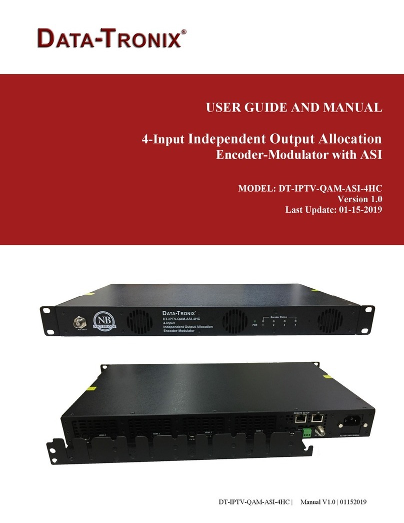
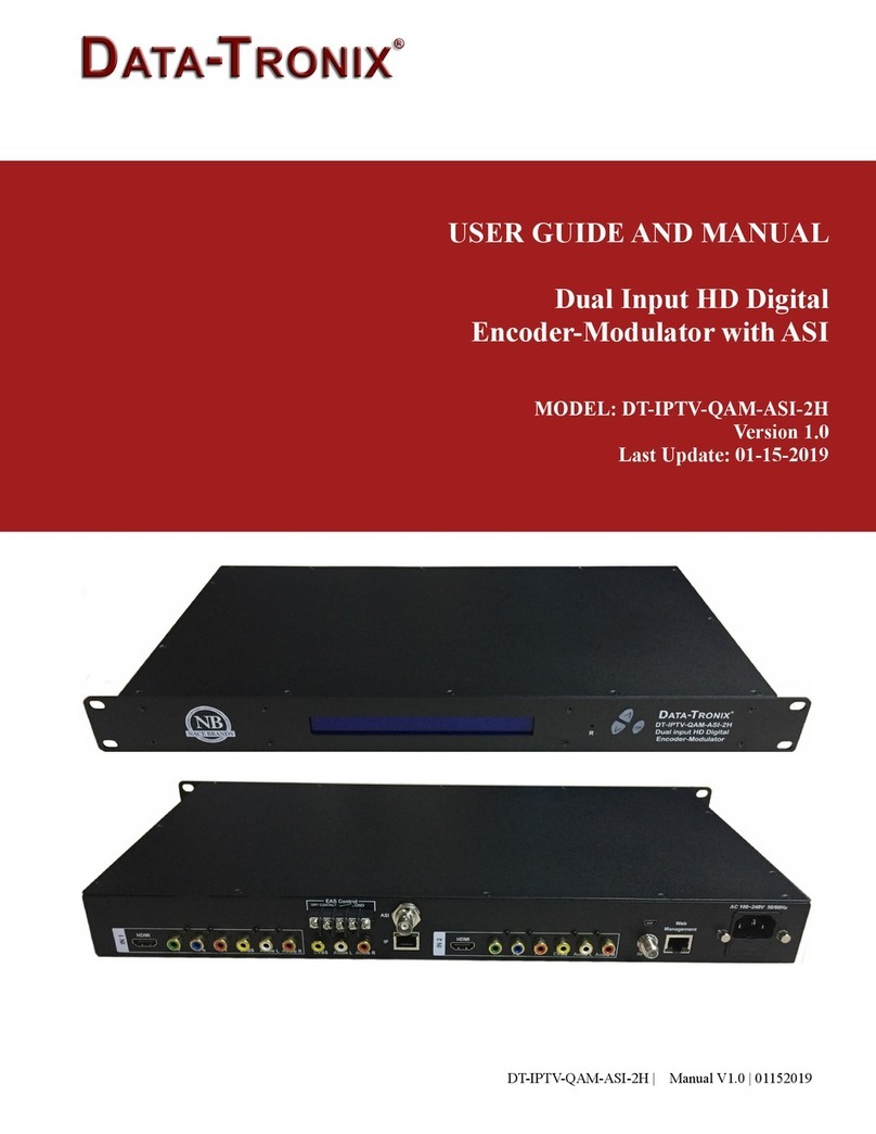
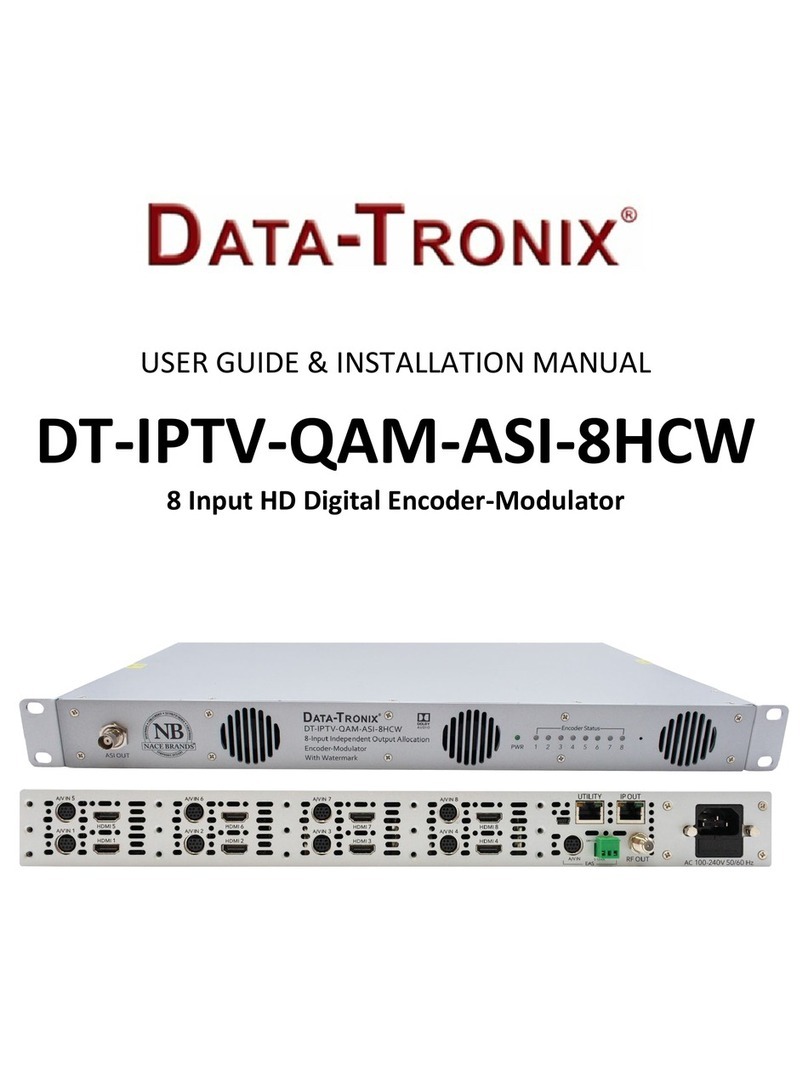
Data-Tronix DT-QAM-AMM-1 User manual

Manual
DT-QAM-AMM-1
User Manual

DT-QAM-AMM-1 Manual
2
Table of Contents
1 GENERAL ................................................................................................................... 3
1.1 Description.......................................................................................................... 3
1.2 Specications ..................................................................................................... 3
2 INSTALLATION............................................................................................................... 4
2.1 Power Supply.......................................................................................................... 4
2.1.1 Operation via external power supply ......................................................... 4
2.2 Connection.............................................................................................................. 4
2.2.1 Connection diagram examples .................................................................. 4
2.3 Navigation and edition of values......................................................................... 5
3 OPERATING INSTRUCTIONS........................................................................................ 5
3.1 Description of controls and components ............................................................ 5
3.2 Starting ............................................................................................................... 6
3.3 Menu................................................................................................................... 6
3.4 Menu Tree .......................................................................................................... 8
3.5 Accessing the Digital Modulator Admin Settings: ............................................... 9
3.5.1 Modulator Settings.................................................................................... 9
3.5.2 Frequency Settings:................................................................................... 9
3.5.3 Video & Audio Settings: ........................................................................... 10
3.5.4 Stream Settings: ...................................................................................... 10
3.5.5 System information: ................................................................................. 11
4 WARRANTY ................................................................................................................. 11

DT-QAM-AMM-1 Manual
3
1 General
1.1 Description
TheDataTronixDT-QAM-AMM-1,HighDenition(HD)Modulator,istheultimatesolutionfor
adding local content seamlessly into a coaxial cable TV network. This innovative device boasts
the ability to generate an MPEG-2 encoded signal in either QAM or ATSC format from an HDMI
input. With its sleek design, it features one HDMI input, one RF output, and one LAN port for
web management - making it the perfect addition to add locally generated content, such as digi-
tal signage and video surveillance.
Thisinnovativeunitcanbeeortlesslyinstalledintoanexistinganalogmicro-modulatorslot,
makingupgradingyoursystemtoHDaneortlessprocess.
Specifications
Input
Video Input HDMI
Audio Input HDMI
Video Input Format 480i/p, 576i/p, 720p, 1080i/p
Closed
Captioning (CC) Composite Video
RF Output
Frequency
Range 57-861 MHz
Output Level 41 dBmV
Channel
Bandwidth 6 MHz
Channel Level
Adjustment 0 dB - 30 dB Typically
MER 35 dB Typically
Attenuation
Step 1 dB per step
Compression
Video MPEG 2
Video
Resolution 1080p 25/30 Max
Video
Bit Rate 18Mbit/sMax
Audio MPEG - 1 Layer 2, AAC-LC, AC3
Connections
HDMI IN HDMI IN
Closed
Captioning (CC) RCA Female 75Ω (Yellow)
RF Out 1 RF Output, Type Female, 75Ω
LAN Web Management
Button Control UP/Down/OK
Micro USB-B S/W Update
General
Modulation
Standard QAM (J83 Annex
B)/ ATSC A/53
Constellation 256 QAM,
64 QAM/8VSB
Bandwidth 6MHz
Channel Type: STD
DC IN 5VDC, 12VDC
Display OLED panel @ 64 x 32 Dots
Operating Limits
Temperature:
41-104°F (5-40°C)
Relative Humidity
80% @ 86°F (30°C)
Dimensions 9.25″ x 1.06” x 3.46”
(235 x 27 x 88 mm)
Weight 0.6294 lbs (0.2855 kg)
Warranty 1 Year Warranty
1.2 Specications

DT-QAM-AMM-1 Manual
4
2 Installation
2.1 Power Supply
Once powered on, the DT-QAM-AMM-1 takes about 15 seconds to become operational.
2.1.1 Operation via external power supply
Use only the rack mount 5V/12V Power-Supply with the DT-QAM-AMM-1.
2.2 Connection
2.2.1 Connection diagram examples
CONNECTION DIAGRAM FOR SINGLE MODULE
Default Static IP address (192.168.1.99).
Default password: 0000
ATTENTION!
FOR PROPER CONFIGURATION YOU MUST USE OUTPUT FREQUENCIES
DIFFERENT FROM THE ONES THAT YOUR TV IS CURRENTLY USING.

DT-QAM-AMM-1 Manual
55
2.3 Navigation and edition of values.
TheDT-QAM-AMM-1isconguredthroughits3keysandwebcontrol.Ingeneral,itisnotnec-
essarytoconguretheinstrumenttogenerateaQAM/ATSC signal compatible with any digital
cable television receiver.
3 Operating Instructions
3.1 Description of controls and components
Display(OLED)
Menu navigation keys
LAN(WebManagement)
RF Output
5VDC,12VDC
HDMI In
Micro USB-B: S/W update
Caption(ClosedCaption)
Indicates HDMI Input
CH 2 Disconnected
CH 2 Connected
Indicates RF Output
RF 00 OFF
RF 00 ON

DT-QAM-AMM-1 Manual
6
3.2 Starting
1. Once powered on, the DT-QAM-AMM-1 takes about 15 seconds to become operational.
You will then see the message “Initial Wait” appear on the display. After 30 seconds the
message “CH 2 & RF 00 ” will show on the display.
2. Connect an Ethernet cable directly to the Web Management Port on the front panel of the
digital modulator.
3. Using the Web application allows management of the device remotely via a
network connection.
3.3 Menu
1. Modulator: Allows users to select either QAM or ATSC output
2. Constellationtypeusedtotransmitsignal(256QAM,64QAM)
3. RF Level Adj: Attenuates the power level of the output signal, in dB, from 0 to -30 dB.
4. Frequency: Sets the frequency value of the output signal. Important: Check that the select-
ed frequency is not already being used by a current television distribution channel.
5. Video Prole Settings: The unit comes with a default setting called NORMAL, which pro-
videsgenerallyacceptedsettingsforthevideoprole.Ifyouwishtocustomizetheseset-
tings according to your preferences, you can switch to the USER DEFINE mode by clicking
on the radio button next to USER DEFINED. 4.1 Min & Max Bitrate: Changes the output
video bitrate. Allowed value is 2000 - 20000.
5.2 Latency:Allows users to change the PCR delay time of video.
Allowed value is 0-1000.
5.3 GOP:ThisfunctionChangestheGroupofPictures(GOP)value.Thesettingwill
specify the order in which intra- and inter-frames are arranged. If the video being
processed does not have a lot of motion, this value should be set to a larger
number. For fast motion video, the GOP should be set to a smaller number.
However, if the GOP is set too small, the video may jitter. If the GOP is too
large the video becomes smoother but may be blurred. The value can be set
between 1 - 60
5.4 Min & Max Quant: Changes the video detail. The lower the Quant value, the more
detail the picture has, but higher relative encoded data rate. If Quant is too small
the video may become jumpy. If Quant is too large the video becomes much
smoother but may be a little blurred. Allowed value is 1 - 31.
• To improve video quality, you can reduce Min Quant and increase the Max Bitrate.
• To make video smoother, you can increase Max Quant and GOP and reduce the Max Bitrate.

DT-QAM-AMM-1 Manual
7
6. Encode Feature: Changes the encoder feature settings.
5.1 1080P to I: 1080p video input to 1080i video output.
5.2 Interlace Enc: Changes the video encoder method. For 1080i and progressive
video input, “I Field” is suggested. For 480i/576i video input, please use I Frame Mode.
7. Audio Codec: It can change the audio codec between MP1 Layer II, AAC-LC and AC3.
8. PMT PID:ChangesthePMT(ProgramMapTable)PID.Allowedvalueis0001~8191.
9. Video PID: Changes the Video PID. Allowed value is 0001 - 8191.
10. Audio PID: Changes the Audio PID. Allowed value is 0001 - 8191.
11. PSIP TSID: PSIP TSID edit.
12. Channel Mode:ChangesthechannelbetweenDTVchannel(two-partchannelnumber)
andLoopchannel(one-partchannelnumber).
13. Major No.: Major no. edit.
14. Minor No.: Minor no. edit.
15. Short Name: Short name edit.
16. Long Name: Long name edit.
17. Source ID: Source ID edit.
18. Setup Date & Time & Weekday: Changes the date, time and weekday of the DT-QAM-
AMM-1. Time will be shown on the display. Note: this setting is not saved to non-volatile
memory. If the instrument loses power, the user has to correct it manually.
19. FW Version: ShowsthermwareversioninstalledintheDT-QAM-AMM-1.Thisoptionisnot
editable.
20. Reboot Device: Select “Reboot “ to reboot the DT-QAM-AMM-1. Select “Reboot to DEF” to
return the DT-QAM-AMM-1 to default values.
21. Device Related:
19.1 Device name: Changesthedevicename.Allows1~7charactersincludingletters,
underline, space and dash.
19.2 Time out (sec.): Changes the display timeout setting. Display becomes
brighter when the front panel is pressed. If no more keys are pressed after this
duration,thedisplaybecomesdarker.Allowedvalueis10~180seconds.
22. Upgrade: DownloadingrmwarefromaUSBdevice.FAT32formattedUSBstorageis
recommended.
23. Auto RF Tune: Factory use only. DO NOT CHANGE!
24. Save Changes: Savesthecurrentcongurationonthenon-volatilememoryof
the DT-QAM-AMM-1.

DT-QAM-AMM-1 Manual
8
3.4 Menu Tree
1 Modulator
1 Modulator QAM QAM, ATSC
1.1 Constellation 256 QAM 64 QAM, 256 QAM
1.2 RF Attenuation 00 dB 00 - 30 dB
1.3 Frequency CH257MHz CH257-CH135861MHz
2.1 RF Level Adjust 00 dB 00 - 30 dB
2.2 Frequency CH257MHz CH257-CH69803MHz
4Save Changes No Yes, No
2Video &
Audio
1
VideoProle Normal Normal,UserDene
VideoProle
(UserDene)
Min Bitrate: 2000 2000 - 50000
Max Bitrate: 18000 2000 - 50000
Latency: 500 0 - 1000
GOP: 16 1 - 60
Min Quant: 5 1 - 31
Max Quant: 12 1 - 31
2Encode
Features
1080PtoI(Disable) Disable, Enable
InterlaceENC.(IField) I Field MO, DE, IFrame Mode
3 Audio Codec AC-3 MPI Layer II, AC-3, AAC-LC
3 Stream
1 PMT PID 32 1 - 8191
2 Video PID 33 1 - 8191
3 Audio PID 36 1 - 8191
4PSIP TSID 100 1 - 65535
5 Channel Mode DTV Channel DTV Channel, Loop Channel
6 Major No. 2 1 - 99
7 Major No. 1 1 - 99
8 Short Name ShoName 1 - 7 Characters
9 Long Name LongName 1 - 15 Characters
10 Source ID 2 1 -4095
5 System
1MAC Address b8-87-1e-16-XX-XX
1 FW Version HW: 0 Rxx SW: 220XXX
R-O: JBAT-80-XXXX
Change per the
Firmware in device
2 DHCP Disable Disable, Enable
3IP Address 192.168.1.99
4 Subnet Mask 255.255.255.0
5Default Gateway 192.168.1.1
7Saves Changes No Yes, No
8 Reboot Device No Yes, No
9 Default No Yes, No
10 SW Update Yes Pleasecheckupgradele!

DT-QAM-AMM-1 Manual
9
3.5 Accessing the DT-QAM-AMM-1 Admin Settings
Adjust the settings listed below using the front panel buttons as described on the previous page.
You must login as described below to edit settings.
3.5.2 Frequency Settings:
3.5.1 Modular Settings:
1. Once powered on, the DT-QAM-AMM-1 takes about 15 seconds to become operational. You
will then see the message “Initial Wait” appear on the display. After 30 seconds the message
“CH 2 & RF 00 ” will show on the display.
2. Press the OK button twice and enter 0000 as the password.
3. Use the UP/DOWN button to display RF EDIT, SYSTEM, DEFAULT, REBOOT mode selection.

DT-QAM-AMM-1 Manual
10
3.5.3 Video & Audio Settings:
3.5.4 Stream Settings:

DT-QAM-AMM-1 Manual
11
3.5.5 System Information:
DATATRONIX 1-Year Limited Warranty
DATATRONIX.(the“Company”)warrants to the OriginalPurchaserthattheitempurchasedis
free from defects in workmanship or material under normal use. This warranty starts on the date
of shipment of the hardware to the Original Purchaser.
During the warranty period, the Company agrees to repair or replace, at its sole option, without
charge to Original Purchaser, any defective component. To obtain service, the Original Purchaser
must return the item to the Company properly packaged for shipping. All defective products must
be returned to the Company within thirty (30) days of failure. Products must be returned with
a description of the failure and Return MerchandiseAuthorization (RMA) number supplied by
the Company. To receive a RMA number and a return shipping address on where to deliver the
hardware, call 610-429-1821. The shipping, and insurance charges incurred in shipping to the
Company will be paid by Original Purchaser, and all risk for the hardware shall remain with the
Original Purchaser until such time as Company takes receipt of the hardware. Upon receipt, the
Company will promptly repair or replace the defective unit, and then return said unit to Original
Purchaser, shipping prepaid. The Company may use reconditioned or like-new parts or units, at
its sole option, when repairing any hardware. Repaired products shall carry the same amount of
outstanding warranty as from original purchase. Any claim under the warranty must include dated
proof of purchase or invoice. In any event, the Company’s liability for defective hardware is limited
to repairing or replacing the hardware.
This warranty is contingent upon proper use of the hardware by Original Purchaser and does
notcover:ifdamageisduetoActsofGod(includingre,ood,earthquake,storm,hurricaneor
othernaturaldisaster),accident,unusualphysical,electrical,orelectromechanicalstress,mod-
ications,neglect,misuse,operationwithmedianotapprovedbytheCompany,tamperingwith
oralteringofthehardware,riot,war,invasion,actofforeignenemies,hostilities(regardlessof
4 Warranty

DT-QAM-AMM-1 Manual
12
whetherwarisdeclared),civilwar,rebellion,revolution,insurrection,militaryorusurpedpoweror
conscation,terroristactivities,nationalization,governmentsanction,blockage,embargo,labor
dispute, strike, lockout or interruption or failure of electricity, air conditioning, or humidity control,
Internet, network, or telephone service.
The warranties given herein, together with any implied warranties covering the hardware, includ-
inganywarrantiesofmerchantabilityortnessforaparticularpurpose,arelimitedindurationto
one year from the date of shipment to the Original Purchaser. Jurisdictions vary with regard to the
enforceability of warranty limitations, and you should check the laws of your local jurisdiction to
ndoutwhethertheabovelimitationappliestoyou.
TheCompanyshallnotbeliabletoyourforlossofdata,lossofprots,lostsavings,special,inci-
dental, consequential, indirect, or other similar damages arising from breach of warranty, breach
of contract, negligence, or other legal action even if the Company or its agent has been advised of
the possibility of such damages, or for any claim brought against your by another party. Jurisdic-
tions vary with regard to the enforceability of provisions excluding or limiting liability for incidental
orconsequentialdamages.Youshouldcheckthelawsofyourlocaljurisdictiontondoutwhether
the above exclusion applies to you.
This warranty allocates risks of product failure between Original Purchaser and the Company.
TheCompany’shardwarepricingreectsthisallocationofriskandthelimitationsofliabilitycon-
tained in this warranty. The warranty set forth above is in lieu of all other express warranties,
whether oral or written. The agents, employees, distributors, and dealers of the Company are not
authorizedtomakemodicationtothiswarranty,oradditionalwarrantiesbindingontheCompa-
ny. Accordingly, additional statements such as dealer advertising or presentations, whether oral
or written, do not constitute warranties by the Company and should not be relied upon.
Thiswarrantygivesyouspeciclegalrights.Youmayalsohaveotherrightswhichvaryfromone
jurisdiction to another.
Table of contents
Other Data-Tronix Media Converter manuals
