Prodys ProntoNet User manual


Prontonet IP Decoder User Manual v211.doc 2
Index
Index......................................................................................2
CE Declaration of Compliance......................................................4
Introduction ............................................................................5
Installation Guide .....................................................................6
II.1 Initial checks ........................................................................6
II.2 Installation...........................................................................6
II.3 The rear panel.......................................................................6
II.3.1 Power .............................................................................7
II.3.2 Ethernet port –the LAN Connector ...........................................8
II.3.3 RS 232 Port.......................................................................9
II.3.4 GPIO Port....................................................................... 10
II.3.4.1. Inputs......................................................................... 10
II.3.4.2. Outputs....................................................................... 10
II.3.5 Audio interfaces............................................................... 11
II.3.5.1. Analog audio Outputs ...................................................... 11
II.3.5.2. AES/EBU Interface.......................................................... 11
II.3.6 Microswitches.................................................................. 11
The Front Panel .....................................................................12
Remote Control......................................................................13
IV.1 General Configuration ........................................................... 16
IV.1.1 Ports: .......................................................................... 17
IV.1.1.1. LAN port:.................................................................... 17
IV.1.1.2. RS232 Port: .................................................................18
IV.1.1.3. SNMP Traps: ................................................................ 19
IV.1.1.4. GPIO Port: .................................................................. 19
IV.1.2 Audio Output:.................................................................22
IV.1.3 System Configuration ........................................................ 22
IV.1.3.1. Exporting / Importing the configuration................................ 26
IV.1.4 Streaming:..................................................................... 26
IV.1.4.1. Rx: Reception parameters. ............................................... 27
IV.1.4.2. Test.......................................................................... 27
IV.1.4.3. Real Time Monitoring ...................................................... 30
IV.1.5 Phone Book:................................................................... 31
IV.1.6 Call Log ........................................................................ 32
IV.2 Controlling the ProntoNet...................................................... 33
IV.2.1 Making Calls:.................................................................. 33
IV.2.2 Disconnecting the Line: ..................................................... 34
IV.2.3 Line Status: ................................................................... 34

Prontonet IP Decoder User Manual v211.doc 3
IV.2.4 Decoder Status:............................................................... 35
IV.3 Alarms............................................................................. 36
IV.3.1 Selecting Alarms.............................................................. 36
IV.3.2 Monitoring Alarms............................................................ 37
IV.3.3 Alarms History ................................................................ 37
How does the ProntoNet IP Decoder work?...................................39
IV.4 About how the Decoder works and automatic searching ................... 39
IV.5 The ProntoNet IP Decoder operation modes.................................. 40
IV.5.1 UNICAST communications ................................................... 40
IV.5.1.1. Establishing a UNICAST connection from the ProntoNet IP Decoder 40
IV.5.1.2. Establishing a MULTICAST Rx communication from the ProntoNet IP
Decoder .............................................................................. 41
IV.6 About the Ancillary Data........................................................ 42
Technical Specifications ..........................................................43
V.1Audio Interfaces .................................................................. 43
V.2Compression algorithms (Decoding)............................................ 43
V.2.1 BANDWIDTH (KHz) ............................................................ 44
Communications Ports................................................................ 45
LAN port.............................................................................. 45
GPIO Port ............................................................................ 45
RS232 Port ........................................................................... 45
V.3Power Supply ...................................................................... 46
Main..................................................................................... 46
Secondary (Optional) .................................................................46
V.4 Dimensions and Weight .......................................................... 46
V.5Environment....................................................................... 46
Disconnection Codes ...............................................................47
Updating the firmware ............................................................48

Prontonet IP Decoder User Manual v211.doc 4
CE Declaration of Compliance
Procesamiento Digital y Sistemas S.L., hereby declares that ProntoNet IP
Decoder bearing the CE168X parking are in comliance with Electromagnetic
Compatibility Directive (89/336/EEC), and the Low Voltage Directive (72/23/EEC)
of the European Union.
A “Declaration of conformity” for ProntoNet IP Decoder is available on file at
Prodys offices in Spain. To obtain this information, contact with
CAUTION
ProntoNet IP Decoder uses a Lithium battery.
Danger of explosion if battery is incorrectly replaced. Replace only with the same
or equivalent type recommended by the manufacturer. Dispose of used batteries
according to the manufacturers instructions.
Your product is designed and manufactured with high quality
materials and components, which can be recycled and reused.
When this crossed-out wheeled bin symbol with black bar underneath
is attached to a product it means that product is covered by the
European Directive 2002/96/EC.
Please, inform yourself about the local separate collection system for
electrical and electronic products.
Please act according to your local rules and do not dispose of your old
products with your normal household waste. The correct disposal of
your old product will help prevent potential negative consequences for
the environment and human health.

Prontonet IP Decoder User Manual v211.doc 5
Introduction
ProntoNet IP Decoder supplements the PRODYS IP range of audio codecs
family. It is based on the features provided in ProntoNet.
ProntoNet IP Decoder is a multi-algorithm stereo audio decoder over IP,
supporting many industry standard coding algorithms such as; G722, MPEG1/2
LayerII, MPEG1/2 LayerIII, MPEG2/4 AAC LC, MPEG4 AAC LD, apt-X
(enhanced and standard) as well as uncompressed linear audio (PCM).
Each ProntoNet IP Decoder fully supports IP (TCP and UDP), connecting via
a 10BaseT/100Base-TX Ethernet port (RJ45 connector). This enables remote
monitoring/configuring and data/audio transportation over data communication
links (LAN, Wan, Internet…).
About this manual
The information is arranged in the following sections:
§Chapter II –Installation Guide.
This chapter provides hardware requirements and instructions for installing
the ProntoNet IP Decoder unit.
§Chapter III –The remote control.
ProntoNet IP Decocer can be controlled from a Web Browser. This chapter
describes how to start it and how to use it.
§Chapter IV –How does the ProntoNet IP Decoder work?
This chapter is a practical guide to help in understanding just how the
ProntoNet IP Decoder unit works under different configurations, especially
the more unusual ones.
§Appendix A –Technical Specifications.
§Appendix B –Disconnection Codes.
This appendix describes the meaning of the disconnecting codes showed on
the display.
§Appendix C –Updating ProntoNet IP Decoderfirmware.
Chapter I
Prontonet IP Decoder User Manual v211.doc 6
Installation Guide
This chapter describes the ProntoNet IP Decoder hardware and user installation.
Theinstallationandservicinginstructionsinthismanualareforusebyqualifiedpersonal.
II.1 Initial checks
Before unpacking unit check its packaging for any signs of damage or
mishandling during transportation, report any damage to the shipping company
immediately. Unpack the unit carefully, if you find any damage or the unit does
not work correctly, you should contact Prodys or its distributor as soon as
possible.
II.2 Installation
The ProntoNet IP Decoder is designed to be housed in a standard 19” rack. The
unit is 44.45mm high (1U, or 1.75 inches). When choosing a suitable place for
installation, please bear the following in mind:
§The position must allow for easy connection of cables to the back of
the unit.
§The front panel must also be accessible, both for connections and to
be able to see the Display, keyboard and LED indicators.
§The air vents must not be obstructed
§We do not recommended that the unit is mounted directly above
other equipment, especially ones that generate a lot of heat.
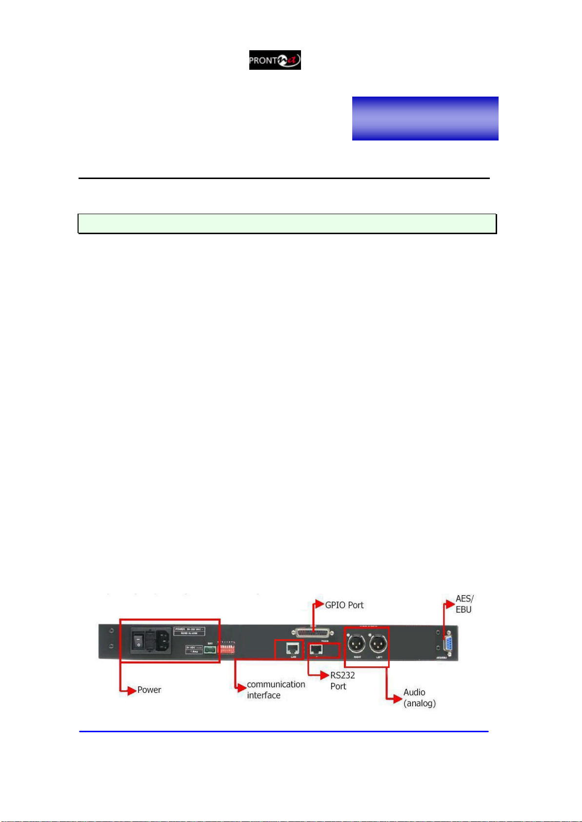
II.3 The rear panel
The majority of the connections of the ProntoNet IP Decoder are found on the
back panel. They are grouped together according to their function, as below:
Chapter II

Prontonet IP Decoder User Manual v211.doc 7
II.3.1 Power
On the back panel you will find the main power inlet. You will also find the main
power switch and the fuse holder. The ProntoNet IP Decoder unit is designed to
take AC universal power, from 100 to 240 VAC with frequency between 50Hz and
60Hz.
You will also find a fuse holder that holds two fuses, one for each phase of input.
When it is necessary to replace either fuse, it is important to make sure that it
complies with the technical specifications outlined below that will ensure
adequate protection.
Fuse requirements:
Fuse type: Type T
Amps 2A
Power 250V
ATTENTION–CHANGINGTHEFUSE
DisconnectthepowercableBEFORE changingthefuse.
VDC SECONDARY POWERSOURCE
§THIS IS OPTIONAL AND DOES NOT COME FITTED AS STANDARD. IT
CAN BE 12, 24 OR 48 VDC.
§The unit will switch automatically from the primary power source to the
back-up power source in the event of a cut in the primary power supply.

Prontonet IP Decoder User Manual v211.doc 8
II.3.2 Ethernet port –the LAN Connector
The LAN socket is an standard 100Base-Tx (10/100 Mbps) Ethernet connection
that takes the typical RJ45 plug. Through this Ethernet port it is possible to
transmit and receive audio, as well as manage the equipment. Next to the
socket there are three LEDs that indicate different states for the connection and
these are very useful in problem-solving situations.
LAN LED’s:
§
Connection to a Hub or Switch
In the majority of cases you can simply connect the unit’s LAN port to your
Ethernet network’s Hub or Switch using an Ethernet cable (CAT5). In this
case you should use a standard ‘straight-through’ Ethernet cable (not a
‘cross-over’ cable). This kind of cable can normally be found in any IT shop.
In any case, this cable is described in more detail below:
§
Connection to a PC
In some cases, such as when you configure the equipment, it is possible
that you will want to connect the unit directly to a PC. In this case the PC
must have a free Ethernet port to connect to and you must use a ‘cross-
over’ Ethernet cable. Again, any good IT shop will stock these cables. This
time the wiring is as follows:

Prontonet IP Decoder User Manual v211.doc 9
II.3.3 RS 232 Port
There is one RS232 port for use as auxiliary data port. These port allow the
reception of data along with encoded audio. Note that this socket is RJ45
connection, as opposed to the typical 9-pin subD connections. To make the
conversion between RJ45 and RS232 there are modular connectors available that
should be wired as follows:
S-Cluster
RJ45
Connector
9-pin female
D-sub
Connector
1 (NC) 1
2 (Rx) 3
3 (GND) 5
4 (NC) 4
5 (NC) 6
6 (GND) 7
7 (Tx) 2
8 (NC) 8
1,4,5,8 must be unconnected
The port is always set to 8 DATA bits, NO parity, 1 START bit and 1 STOP bit.
The bit rate can be adjusted to between 300 and 9600 bps via software.
The ProntoNet IP Decoder acts as a DCE device, therefore the connection to
each of the RS232 ports is wired in the following way:
ProntoNet IP Decoder –Pin 7 connector RJ45.........................Pin 2 PC
ProntoNet IP Decoder –Pin 2 connector RJ45.........................Pin 3 PC
ProntoNet IP Decoder –Pin 3,6 connector RJ45......................Pin 5 PC
The ProntoNet IP Decoder ignores hardware handshaking signals.
Prontonet IP Decoder User Manual v211.doc 10
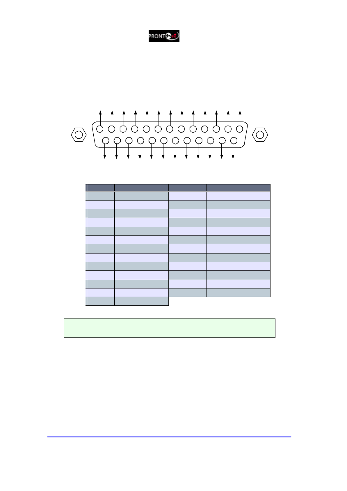
II.3.4 GPIO Port
AsubD 25 pin socket provides a general purpose connection with 7 inputs and 7
outputs. The connections must be wired according to the following diagram:
12345
15
9 678
1617181920
10111213
25 24 23 22 21 14
NC
NC
NC
NC
OUT1
OUT3
OUT5
OUT7
NC
OUT2
OUT4
OUT6
GND
VCC
NC
IN2
IN4
IN6
NC
NC
IN1
GND
IN3
IN5
IN7
Pin Function Pin Function
1+5VDC 14 IN 7
2IN 6 15 IN 5
3IN 4 16 IN 3
4IN 2 17 IN 1
5NC 18 NC
6NC 19 NC
7GND 20 GND
8OUT 7 21 OUT 6
9OUT 5 22 OUT 4
10 OUT 3 23 OUT 2
11 OUT 1 24 NC
12 NC 25 NC
13 NC
Pin 1 is connected to +5 volts. If you need it , run this power supply through
your device with a resistor in series to limit the maximum current to 300 mA.
II.3.4.1.Inputs
The inputs are active for grounding (active low).
II.3.4.2.Outputs
The outputs are “open collector”. They allow an output of 5VDC on one pin to
facilitate interconnection with the outputs. Each output supports up to a
maximum of 40VDC / 40 mA and will require a pull-up resistor to function with
other logic inputs. An appropriate value is 2.2 Kohms.

Prontonet IP Decoder User Manual v211.doc 11
II.3.5 Audio interfaces
II.3.5.1. Analog audio Outputs
The analog audio outputs is connected through the XLR connections on the rear
panel. The wiring conforms to the following scheme:
Pin Función
1Ground
2Audio+
3Audio-
These outputs are electronically balanced with a maximum level of
+22 dBu.
II.3.5.2. AES/EBU Interface
An AES/EBU interface is available via the subD 9 pin connector on the rear panel
of the unit. This connector provides the option to connect an externally
synchronised signal. The user can select via software if the digital output is to
synchronise with an external sync signal. The connector is wired in the following
way:
Pin Function Pin Function
1X6X
2GND 7SYNC +
3SYNC -8GND
4GND 9AES/EBU OUT +
5AES/EBU OUT -
II.3.6 Microswitches
There are 8 microswitches on the back panel which are reserved for special
functions. Before turning on the unit the user must check that they are
configured according to the following diagram, which is the standard start-up
configuration:

Prontonet IP Decoder User Manual v211.doc 12
The Front Panel
The front panel of the ProntoNet IP Decoder has two arrays of vu-meters and
leds that allow you to monitor the status of the unit. The leds are laid out in the
following manner:
There are two vu-meters in dBFs,
one for each input channel.
CON led: When this led is on, It
indicates that the unit is
connected.
FRM led: This led informs about
the synchronization status of the
decoder.
LAN: LAN physical connection.
It goes on when the unit is
connected to a LAN.
SYS: System led. It blinks during
the start phase. It will light
fixed at soon as the unit is ready.
Chapter III

Prontonet IP Decoder User Manual v211.doc 13
Remote Control
ProntoNet IP Decoder can be controlled remotely by using an Internet Explorer
web browser connected through the LAN port. The computer can be locally
connected directly via a crossover CAT-5 cable, or remotely from a computer
connected to the LAN.
To access the ProntoNet IP Decoder from the Internet Explorer, enter the IP
address of the unit in the address bar. Keep in mind that the ProntoNet IP
Decoder factory IP address is 192.168.100.100 and it could be necessary to
modify the network configuration of the computer on which the web browser is
running.
InstallationRequirements
1.-Pentium 166 or higher.
2.-64MB RAM minimum.
3.-Operating Systems:
Microsoft Windows XP, Microsoft Windows 2000,
Microsoft Windows NT 4.0 Service Pack 6 or higher,
Microsoft Windows Millennium Edition (ME), Microsoft Windows 98.
4.-Microsoft Internet Explorer 5.0 orhigher.
The screen resolution must be 1024x768 minimum.
The first time that the computer accesses the ProntoNet IP Decoder it is
necessary to install the software. The computer will show the following
window:
The unit is supplied with the following IPaddress: 192.168.100.100
Chapter IV

Prontonet IP Decoder User Manual v211.doc 14
To access the ProntoNet IP Decoder from the Internet Explorer enter the IP
address of the unit in the address bar as shown here:
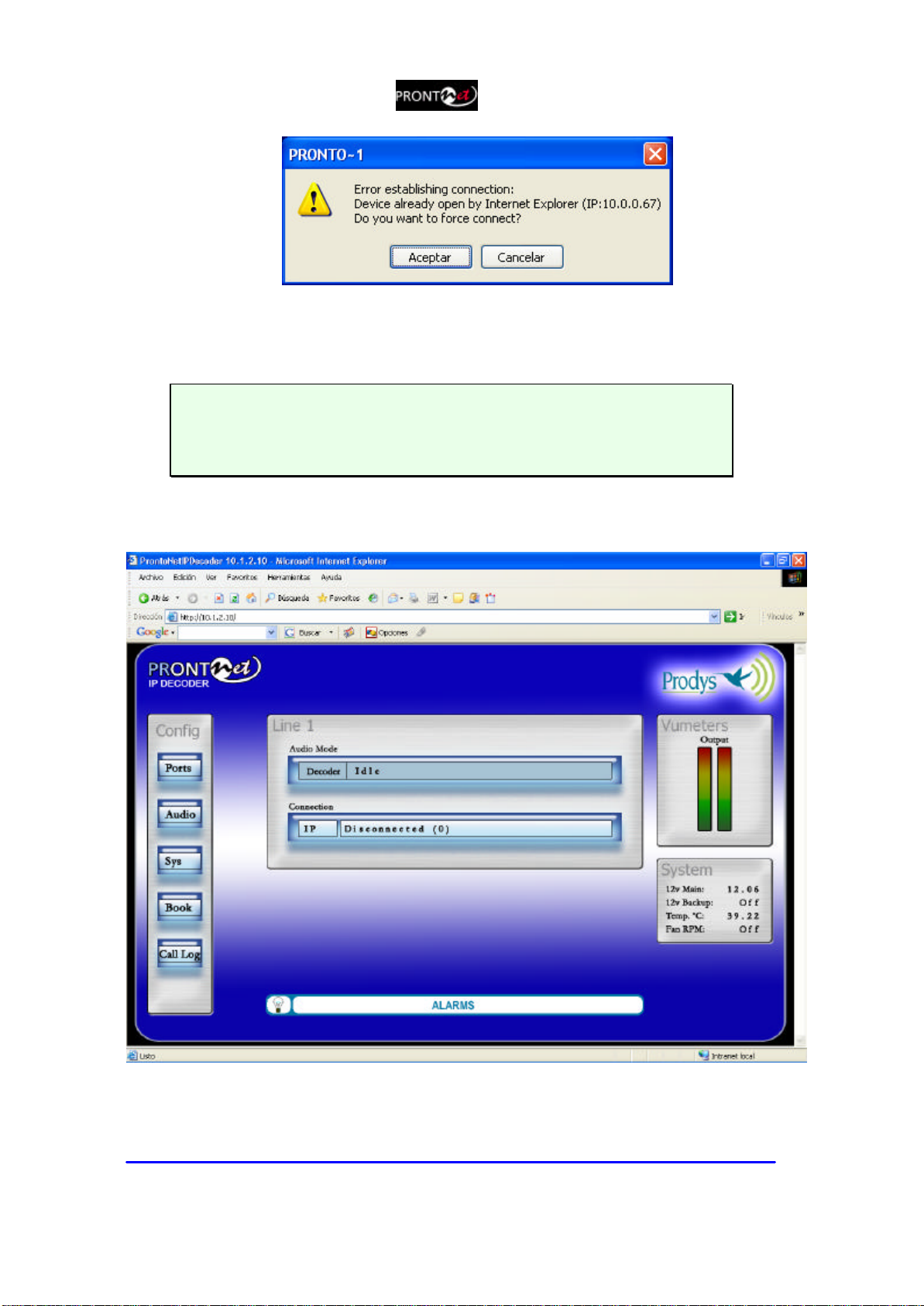
User can choose whether to monitor or to control ProntoNet IP Decoder from the
Web Page. Bear in mind that only one page at the same time can control the
unit. However, It is possible to monitor the unit from several web browsers
simultaneously.
If a unit is already being controlled by a web page and we try to get the control
from another website, a message will appear. This message will indicate that the
unit is already being controlled from another PC and the IP address of this
computer.
Prontonet IP Decoder User Manual v211.doc 15
It is possible to get the control by pressing OK. Then, the connection of
the old owner will be closed and the unit will be blocked for new
controller.
This system is fully integrated with the ProdysControl. In that way, the
control from/to ProdysControl can be revoked. It is possible to have a unit
being controlled by ProdysControl and at the same time, web browsers
monitoring the same unit, etc…
Once the password is entered correctly, the web browser will display the “Home
Page”:
The ProntoNet IP Decoder Web page is arranged in three main areas:

Prontonet IP Decoder User Manual v211.doc 16
§General Configuration area. Œ
§Control area. •
§Monitor area. Ž
By clicking on any button on the menu bar or any highlighted zone, individual
configuration pages are displayed.
IV.1 General Configuration
There are the following options:
§Ports: To configure the ProntoNet IP Decoder Ports.
§Audio: To configure the audio settings.
§Sys: System configuration.
§Book: To edit the phone book.
§Call Log: An history report has been included to record the input and output
calls according to the following information: telephone/IP, audio modes, date
and start/end time, length of each call, etc…
Œ
•
Ž

Prontonet IP Decoder User Manual v211.doc 17
IV.1.1 Ports:
By clicking on the PORTS icon the port configuration dialog appears. In the left
side the ports can be selected. The right window shows the window dialog to
configure the selected port. For example, if we select the LAN port:
IV.1.1.1. LAN port:
ProntoNet IP Decoder allows to assign the IP parameters both manually and
automatically (DHCP).
Ø
Manually àUser must enter the following IP parameters manually:
1. IP address.
2. Mask.
3. Gateway IP address
Ø
Automatically àCheck “Obtain an IP address automatically” option to get
the configuration automatically from a DHCP Server.
By setting DHCP, the unit will receive its IP parameters when starting. These
IP settings might be different from time to time, that is why ProntoNet IP
Decoder supports RIP2 protocol. This protocol allows the user to set an
‘internal’ IP address, in order that the unit can be identified regardless of the
IP settings provided by the DHCP server.

Prontonet IP Decoder User Manual v211.doc 18
IV.1.1.2. RS232 Port:
There is one RS232 port for use as auxiliary data port. This port allow the
transmission and reception of data along with encoded audio. This port is always
set to 8 DATA bits, NO parity, 1 START bit and 1 STOP bit. The bit rate can be
adjusted to between 300 and 9600 bps via software.
Prontonet IP Decoder User Manual v211.doc 19
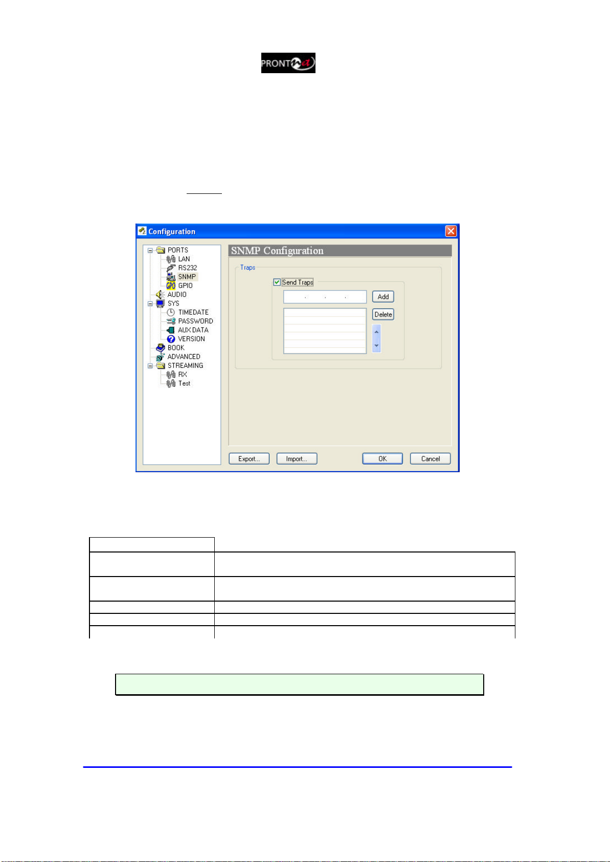
IV.1.1.3. SNMP Traps:
From this option it is possible to select the IP address where the SNMP traps will
be sent. An SNMP manager located at this IP address, will receive and process
the information according to the SNMP protocol. These SNMP traps will notify
alarm information, that is, an SNMP trap will be sent when an alarm is activated
or deactivated, with the time and type of alarm. For this to happen, alarms have
to be enabled (see Alarms). ProntoNet IP Decoder can be fully monitored though
SNMP protocol.
IV.1.1.4. GPIO Port:
From this option the inputs and outputs of the GPIO port are configured.
INPUTS
Connect Line 1
When this input is activated, the ProntoNet will proceed
automatically to connect the line 1.
Disconnect Line 1 When this input is activated, th
e ProntoNet will proceed
automatically to disconnect the line 1.
Mute Left When this input is activated, the left audio output will be muted.
Mute Right When this input is activated, the right audio output will be muted.
Acknowledge alarms When this input is activated, the alarms will be acknowledged.
§The inputs are activated by grounding

Prontonet IP Decoder User Manual v211.doc 20
OUTPUTS
Transparent
Under this configuration, the state of the output will be the same
that its homologous input has in the ProntoNet connected in the
other end.
Line 1 Connected The output will be activated when the line 1 is connected.
Line 1 Disconnected The output will be activated when the line 1 is disconnected.
Decoder 1 Framed The output will be activated when the Decoder 1 is Framed.
Decoder 1 NOT framed The output will be activated when the Decoder 1 is NOT Framed.
Alarm Active The output will be activated when one Alarm is activated.
Alarm NOT Active
The output will be activated when there are NOT Alarms
activated.
§Transparent configurationonly works with audio algorithms that support
ancillarydataandhavebeenpreviouslyactivated.
When a GPO is configured to monitor alarms (“Alarm active”), It is posible to
select which alarms will enable this output.
Other manuals for ProntoNet
3
Table of contents
Other Prodys Media Converter manuals


Popular Media Converter manuals by other brands


H&B
H&B TX-100 Installation and instruction manual

Bolin Technology
Bolin Technology D Series user manual

IFM Electronic
IFM Electronic Efector 400 RN30 Series Device manual

GRASS VALLEY
GRASS VALLEY KUDOSPRO ULC2000 user manual

Linear Technology
Linear Technology DC1523A Demo Manual

Lika
Lika ROTAPULS I28 Series quick start guide

Weidmuller
Weidmuller IE-MC-VL Series Hardware installation guide

Optical Systems Design
Optical Systems Design OSD2139 Series Operator's manual

Tema Telecomunicazioni
Tema Telecomunicazioni AD615/S product manual

KTI Networks
KTI Networks KGC-352 Series installation guide

Gira
Gira 0588 Series operating instructions

Lika
Lika SFA-5000-FD user guide