manuals.online logo
Brands
  1. Home
  2. •
  3. Brands
  4. •
  5. Data Video
  6. •
  7. Switch
  8. •
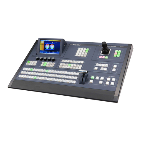
  9. Data Video SE-500 User manual

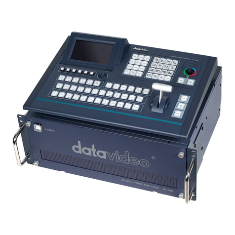
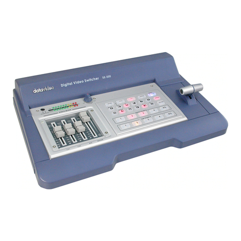
Data Video SE-500 User manual

Other manuals for SE-500

3

Other Data Video Switch manuals

Data Video SE-700 User manual

Data Video

Data Video SE-700 User manual

Data Video OBV-2850 User manual

Data Video

Data Video OBV-2850 User manual

Data Video SE-2850 User manual

Data Video

Data Video SE-2850 User manual

Data Video SE-1000 User manual

Data Video

Data Video SE-1000 User manual

Data Video SE-600 User manual

Data Video

Data Video SE-600 User manual

Data Video SE-2800 User manual

Data Video

Data Video SE-2800 User manual

Data Video DAC-10 Specification sheet

Data Video

Data Video DAC-10 Specification sheet

Data Video SE-2200 User manual

Data Video

Data Video SE-2200 User manual

Data Video SE-900 User manual

Data Video

Data Video SE-900 User manual

Data Video DAC-200 User manual

Data Video

Data Video DAC-200 User manual

Data Video iCast 10NDI User manual

Data Video

Data Video iCast 10NDI User manual

Data Video SE-3000 User manual

Data Video

Data Video SE-3000 User manual

Data Video DAC-10 User manual

Data Video

Data Video DAC-10 User manual

Data Video SE-1200MU User manual

Data Video

Data Video SE-1200MU User manual

Data Video SE-2800 User manual

Data Video

Data Video SE-2800 User manual

Data Video SE-3000 User manual

Data Video

Data Video SE-3000 User manual

Data Video SE-500 User manual

Data Video

Data Video SE-500 User manual

Data Video DAC-10 Specification sheet

Data Video

Data Video DAC-10 Specification sheet

Data Video SE-650 User manual

Data Video

Data Video SE-650 User manual

Data Video SE-4000 User manual

Data Video

Data Video SE-4000 User manual

Data Video SE-600 User manual

Data Video

Data Video SE-600 User manual

Data Video DVK-400 User manual

Data Video

Data Video DVK-400 User manual

Data Video SE-2800 User manual

Data Video

Data Video SE-2800 User manual

Data Video SE-2000 User manual

Data Video

Data Video SE-2000 User manual

Popular Switch manuals by other brands

SMC Networks SMC6224M Technical specifications

SMC Networks

SMC Networks SMC6224M Technical specifications

Aeotec ZWA003-S operating manual

Aeotec

Aeotec ZWA003-S operating manual

TRENDnet TK-209i Quick installation guide

TRENDnet

TRENDnet TK-209i Quick installation guide

Planet FGSW-2022VHP user manual

Planet

Planet FGSW-2022VHP user manual

Avocent AutoView 2000  AV2000BC AV2000BC Installer/user guide

Avocent

Avocent AutoView 2000 AV2000BC AV2000BC Installer/user guide

Moxa Technologies PT-7728 Series user manual

Moxa Technologies

Moxa Technologies PT-7728 Series user manual

Intos Electronic inLine 35392I operating instructions

Intos Electronic

Intos Electronic inLine 35392I operating instructions

Cisco Catalyst 3560-X-24T Technical specifications

Cisco

Cisco Catalyst 3560-X-24T Technical specifications

Asante IntraCore IC3648 Specifications

Asante

Asante IntraCore IC3648 Specifications

Siemens SIRIUS 3SE7310-1AE Series Original operating instructions

Siemens

Siemens SIRIUS 3SE7310-1AE Series Original operating instructions

Edge-Core DCS520 quick start guide

Edge-Core

Edge-Core DCS520 quick start guide

RGBLE S00203 user manual

RGBLE

RGBLE S00203 user manual

Thrustmaster FLIGHT SIMULATOR X quick guide

Thrustmaster

Thrustmaster FLIGHT SIMULATOR X quick guide

Southwire SURGE GUARD 41390 RVC troubleshooting guide

Southwire

Southwire SURGE GUARD 41390 RVC troubleshooting guide

Buhler Nivotemp NT 61 Brief instructions

Buhler

Buhler Nivotemp NT 61 Brief instructions

Kramer VS-41HDCP user manual

Kramer

Kramer VS-41HDCP user manual

Techly IDATA AU-270 user manual

Techly

Techly IDATA AU-270 user manual

Belkin F1U109 user manual

Belkin

Belkin F1U109 user manual

manuals.online logo
manuals.online logoBrands
  • About & Mission
  • Contact us
  • Privacy Policy
  • Terms and Conditions

Copyright 2025 Manuals.Online. All Rights Reserved.

Ü·¹·¬¿´ Ê·¼»± Í©·¬½¸»®
ÍÛóëðð
Û®®±®ÿ
×ÒÍÌÎËÝÌ×ÑÒ ÓßÒËßÔ
ج¬°æññ©©©ò¼¿¬¿ª·¼»±ó¬»µò½±³
Rev 300606
1
Table of Contents
Warnings and Precautions 3
Radio and Television Interference 3
Warranty 4
Disposal 4
Introduction 4
Introduction 4
Product overview 5
Features 5
Packing List 5
Installation, Connections, Set Up 6
Some General Notes on Installation 6
Power Up State 6
Connecting Video sources 7
Connecting Audio sources 7
Outputs and Monitoring 7
Audio Mixer 8
RS-232 control 8
Tally Light output 8
MIDI control 8
Quick Start 9
Front panel 9
Rear panel 13
Selecting video input formats and adjusting audio levels 16
Selecting video output format 16
Using Video and Audio Monitors 16
Cutting between sources 16
Dissolving between sources 17
Other Transitions between sources 17
Effects 17
Controls and Operations 19
Video Source 19
Color Processor 20
Menu 20
Audio Inputs, Levels, and Meters 22
Using Transitions 23
Selecting a Transition: Fade, Wipe 23
Playing a Transition Manually 23
Playing a Transition Automatically 23
List of Transitions 24
Using Effects 26
Effects: Quad 27
Effects: Split 27
Effects: Picture in Picture 27
Freeze 27
Border 28
Background 28
2
Sample applications 29
Four Camera Shoot: Live Stage Performance/Sporting Event 30
Live Conference 31
Live Event Mixing: Club VJ/Concert 32
Using SE-500 with CG-100 for Titles/Graphics/Logos overlay 33
Troubleshooting / FAQ 34
No power 34
No image at output / S-Video output is black and white 34
Audio clipping 34
Frozen image at output 34
Image distortions etc 34
How does RS 232 work in practice 34
Appendix 35
Glossary of terms 35
Tech notes (Video Standards, Formats, and Quality; Monitor Calibration) 37
Specifications 40
Useful Accessories 42
RS-232 Remote Control Commands 45
MIDI Control Commands 50
Tally Pinouts cross reference between the TLM-404 & the SE-500 52
Service and Support 54
3
Warnings and Precautions
1. Read all of these warnings and save them for later reference.
2. Follow all warnings and instructions marked on this unit.
3. Unplug this unit from the wall outlet before cleaning. Do not use liquid or aerosol cleaners. Use a
damp cloth for cleaning.
4. Do not use this unit in or near water.
5. Do not place this unit on an unstable cart, stand, or table. The unit may fall, causing serious damage.
6. Slots and openings on the cabinet top, back, and bottom are provided for ventilation. To ensure safe
and reliable operation of this unit, and to protect it from overheating, do not block or cover these
openings. Do not place this unit on a bed, sofa, rug, or similar surface, as the ventilation openings on
the bottom of the cabinet will be blocked. This unit should never be placed near or over a heat
register or radiator. This unit should not be placed in a built-in installation unless proper ventilation is
provided.
7. This product should only be operated from the type of power source indicated on the marking label
of the AC adapter. If you are not sure of the type of power available, consult your Datavideo dealer
or your local power company.
8. Do not allow anything to rest on the power cord. Do not locate this unit where the power cord will be
walked on, rolled over, or otherwise stressed.
9. If an extension cord must be used with this unit, make sure that the total of the ampere ratings on the
products plugged into the extension cord do not exceed the extension cords rating.
10. Make sure that the total amperes of all the units that are plugged into a single wall outlet do not
exceed 15 amperes.
11. Never push objects of any kind into this unit through the cabinet ventilation slots, as they may touch
dangerous voltage points or short out parts that could result in risk of fire or electric shock. Never
spill liquid of any kind onto or into this unit.
12. Except as specifically explained elsewhere in this manual, do not attempt to service this product
yourself. Opening or removing covers that are marked Do Not Remove may expose you to
dangerous voltage points or other risks, and will void your warranty. Refer all service issues to
qualified service personnel.
13. Unplug this product from the wall outlet and refer to qualified service personnel under the following
conditions:
a. When the power cord is damaged or frayed;
b. When liquid has spilled into the unit;
c. When the product has been exposed to rain or water;
d. When the product does not operate normally under normal operating conditions. Adjust only
those controls that are covered by the operating instructions in this manual; improper
adjustment of other controls may result in damage to the unit and may often require
extensive work by a qualified technician to restore the unit to normal operation;
e. When the product has been dropped or the cabinet has been damaged;
f. When the product exhibits a distinct change in performance, indicating a need for service.
Radio and Television Interference
UNITED STATES: The equipment described in this manual generates and uses radio frequency energy. If it
is not installed and used in accordance with the instructions in this manual, it may cause interference with
radio and television reception.
This equipment has been tested and found to comply with the limits for a Class B digital device, pursuant to
Part 15 of the FCC Rules. These limits are designed to provide reasonable protection against harmful
interference in a residential installation. This equipment generates, uses, and can radiate radio frequency
energy, and if not installed and used in accordance with these instructions, may cause harmful interference
to radio communications. However, there is no guarantee that interference will not occur in a particular
installation. If this equipment does cause harmful interference to radio or television reception, which can be
determined by turning the equipment off and on, the user is encouraged to try to correct the interference by
one or more of the following measures:
1. Reorient or relocate the receiving antenna;
2. Increase the separation between the equipment and the receiver;
4
3. Connect the equipment into an outlet on a circuit different from that to which the receiver is
connected.
If necessary, consult your dealer or an experienced radio/TV technician for help and/or additional
suggestions.
N.B.: Changes or modifications not expressly approved by the party responsible for compliance
could void the users right to operate this equipment.
Peripherals used in conjunction with this equipment must be connected via shielded interface cables. Use of
unshielded interface cables may result in interference to radio and TV reception, and may void the users
right to operate this equipment.
Warranty
Datavideo warrants that the equipment it manufactures shall be free from defects in material and
workmanship for a period of 12 months from the date of product purchased. If equipment fails due to such
defects, Datavideo will, at its option, repair or provide a replacement for the defective part or product.
Equipment that fails after the warranty period, has been operated or installed in a manner other than that
specified by Datavideo, or has been subjected to abuse or modification, will be repaired for time and material
charges at the Buyers expense. This warranty does not affect your statutory rights within the Country of
purchase.
For EU Customers only - WEEE Marking.
This symbol on the product indicates that it will not be treated as household waste. It must be handed over to
the applicable take-back scheme for the recycling of electrical and electronic equipment. For more detailed
information about the recycling of this product, please contact your local Datavideo office.
Introduction
Thank you for purchasing Datavideos SE-500 Digital Video Switcher. We hope you will be pleased with your
purchase, and with what you can achieve with this advanced piece of technology. In order to get the most
out of your new switcher, we recommend that you spend some time getting familiar with this manual, as it will
describe in detail all the functions of this unit. In addition, youll find some useful background information on
video and audio, and some detailed examples of ways to use your new switcher.
If you are experienced in video production, you may want to immediately take a look at the Quick Start
section on °¿¹» ç
5
Product Overview
The Datavideo SE-500 is an analog input, digital processing video switcher. The SE-500 includes 4 groups
of video input (4 x composite & 4 x S-Video), a 3 channel audio mixer, 2 microphone inputs, color correction,
digital video transition effects, MIDI control interface, Tally out, RS-232 remote control interfaceand many
more professional features.
A built in TBC in each channel with YUV 4:2:2 frame synchronizer for Composite, and S (Y/C) inputs and
outputs assures stable and high quality video from virtually any source. A built in R.G.B. Color Processor and
a Color Corrector for each video input, with settings that are saved, allow you to fine tune your video. The
SE-500 has 15 different digital effects, which include Quad, Split, PIP, Wipes, and Fade.
Additionally, the SE-500 includes a truly unique feature Quad Preview. This preview output displays both
tally light signals, and next video effects indicator. The operator can use one single monitor to observe four
video input sources, camera activities, and video transition effects. The SE-500 has all the popular features
of many more expensive mixers and it is extremely compact in size. Now you can shoot, mix, and edit, all
within this compact size digital switcher.
With the Datavideo DAC-6 (DV to Composite, Y/C, and Component converter), VP-314 (DV Repeater), and
10, 20, 40meter DV cables, you may use DV cameras to feed video from up to 200 meters away.
Features
Digital Processor, high image quality
Four inputs of S-Video (Y/C) and Composite video
Quad video preview monitor output with tally & transition indicators on screen
Optional YUV output  via supplied breakout cable
Quad, Split, PIP, Wipe, and Fade digital video effects
T-Bar control of digital video effect transitions
Color processor for video correction
RS232 remote control
MIDI control interface
Tally output
Audio mixer with two microphone channels and one auxiliary input
Packing List
1. SE-500 switcher x 1
2. BNC to RCA 1.2m cable x 2
3. S-Video 1.2m Cable x 1
4. YUV Breakout cable (BNC x 3 to S(Y/C)+BNC cable) 1.2m x 1
5. RCA to RCA stereo cable 1.5m x 1
6. AC/DC Switching adapter x 1
7. BNC to RCA connector x 2
8. Instruction Manual x 1
6
Installation, Connections, Set up
Some General Notes on Installation
There are a few other things to be aware of when you are installing and integrating the SE-500. Please make
sure you have read the Warnings and Precautions section on °¿¹» íò
The SE-500 sends and receives analog signals except the RS-232, MIDI, and Tally. You need to be aware
that cable lengths, impedance, crossing power cords, and adaptors might interfere with video transmission.
The cautions below, with the exception of physical damage, will give you the general idea about cabling for
analog video or audio.
We strongly recommend you use analog video and audio cables that are roughly the right length to connect
between components. The longer the cable, the more noise and deterioration of the video signal can be
introduced. We strongly recommend that you check the integrity of each analog cable before installation by
using a continuity tester (available from most electronic and video supply stores). Cables can go bad over
time, with use, by someone walking on them, carts rolling over them, or even for no apparently good reason.
It will happen eventually. Have a continuity tester handy and save yourself some troubleshooting headaches.
Make sure you dont run video/audio cables and power lines together, on top of each other, or across each
other. This is another good way to introduce noise and signal degradation.
Cable connectors will eventually become dirty or oxidation will start. The dirt can cause a bad connection or
introduce noise in the signal. It is advisable to buy some electrical contact cleaning products.
Use adaptors if you must, but keep in mind that each connector is one more accident waiting to happen, one
more place the signal can be degraded or broken.
Finally, for examples of how to connect and integrate the SE-500 into a variety of set ups, take a look at the
brief Quick Start on °¿¹» ç and the more in depth explanations in Sample Applications on °¿¹» îç.
Power up State
When you first power up the SE-500, you will need to check each channel s connection and set the audio
levels. All the setting will be retained except color bar output, see MENU on °¿¹» îð.
At power up, channel 1 will be the selected Main Video Source and channel 2 will be the selected Sub Video
Source.
Settings that are retained are: color correction settings; remote control setting; transition setting; video effect
setting, video output settings and background color.
7
Connecting Video Sources
There are two types of plugs used for video signals on the SE-500: BNC, and S-video.
BNC connectors look like this on the cable end. The connector slides over the connector on
the SE-500 and is locked in place with a push in and clockwise turn. The big virtue of these
connectors, which are the standard for almost all professional video applications, is that
they lock in place and cannot be accidentally dislodged.
S-video plugs (also known as Y/C) have 4 tiny pins in them, which carry a separated Y
(luminance) and C (chroma) video signal and provide a much better quality video signal
than composite. These plugs have a tiny bar in them to assure correct alignment in the
socket. They need to be pressed firmly in place, but very carefully, as the little pins can
bend easily. Align plug and socket and push straight in, firmly.
Connecting Audio Sources
The SE-500 uses 2 kinds of plugs for audio connections: RCA and 1/4 inch jack plugs. There are lots of
different names for these plugs. Fortunately for us all, they are not easily confused in the size and shape
departments, so well show you some pictures.
RCA plugs (also sometimes known as phono plugs, cinch, or tulips) are used
for line level audio, such as the connections between a CD player and amp.
The SE-500 uses these in stereo pairs, white for left and red for right, at the
audio input and output sections.
1/4 inch jack plugs got their name, some say, because they used to be used to
manually patch together phone lines in the old central switchboard days. They
come in mono and stereo configurations: the mono has one dark band around
the plug, the stereo has two. The SE-500 uses a mono plug on MIC CH1 and mono
plugs for MIC CH2.
If you need to use balanced audio inputs or outputs, for low impedance
microphones or connections with other professional audio gear, you need to use
an impedance matching device to convert low to high impedance (and/or vice
versa). For example Datavideo BAC-03 ø±² °¿¹» ìì ÷
Outputs and Monitoring
Your particular set up and application for the SE-500 will determine what video and audio devices you
connect to the outputs. Take a look at the Sample Applications,°¿¹» îç for some examples. While all the
outputs of the SE-500 are very high quality, keep in mind that the video quality of the various formats, in
descending order, goes like this: Y.U.V. (analog component), Y/C (S-video), and Composite. Audio outputs
are all line level, suitable for connecting to an amp, VCR, or video projector (for example).
BNC
S-Video
RCA
¼ Mono Jack
¼ Stereo Jack
8
We cant stress enough the importance of good monitoring systems. If something doesnt look or sound right
at the last stage of the signal path, the Main output, it can only be easily corrected if you can pinpoint where
in the signal path the problem is being introduced.
Certain set ups will benefit greatly by being able to
monitor the video of each input channel, as well as
the Main output. High quality headphones allow
you to hear the audio with far fewer intermediate
steps and far more accuracy, thanks to the
Headphone control on the front panel, than going
through an amp and speakers. We suggest both
methods of monitoring, and listening to the sound
through a video monitors speakers is also a good
idea. Needless to say, if you are outputting to a
record deck, you should be able to easily monitor
the output of that device as well.
Audio Mixer
An Audio Mixer with two mono microphone inputs and stereo Aux input allows you to adjust and
balance the volume from various audio sources.
RS-232 control
The RS-232 Control Port enables control of the SE 500 from a PC or other device thru the RS-232 port.
Connects to PC RS-232 serial interface for remote controlled by PC application software. Refer to the
Appendix detail of RS-232 Remote Control Protocol, °¿¹» ìë.
Tally control
The tally output allows you to send out tally light signals. Refer to the Appendix detail of tally pinouts
cross reference, °¿¹» ëî.
MIDI control
Connects to other MIDI devices, such as MIDI keyboard, and electronic piano. Refer to the Appendix
detail of MIDI Control Protocol, °¿¹» ëð.
Connecting a Datavideo TLM-70D 7 TFT LCD for
preview video monitoring, page 43.
9
Quick Start
SE-500 Front Panel
9. Background color selection/Menu
10. Border On/Off
11. T-Bar
12. Transition Effect preview
13. Main Video Source selectors
14. Sub Video Source selectors
15. Transition mode selectors
1. Audio faders
2. Headphone Socket
3. Audio meters
4. Headphone Volume Control
5. Video Effect: Quad
6. Video Effect: Split
7. Video Effect: PIP
8. Video Effect: Freeze
1
2
3 4 5 6
11
7 8 9
15
10
12
14 13