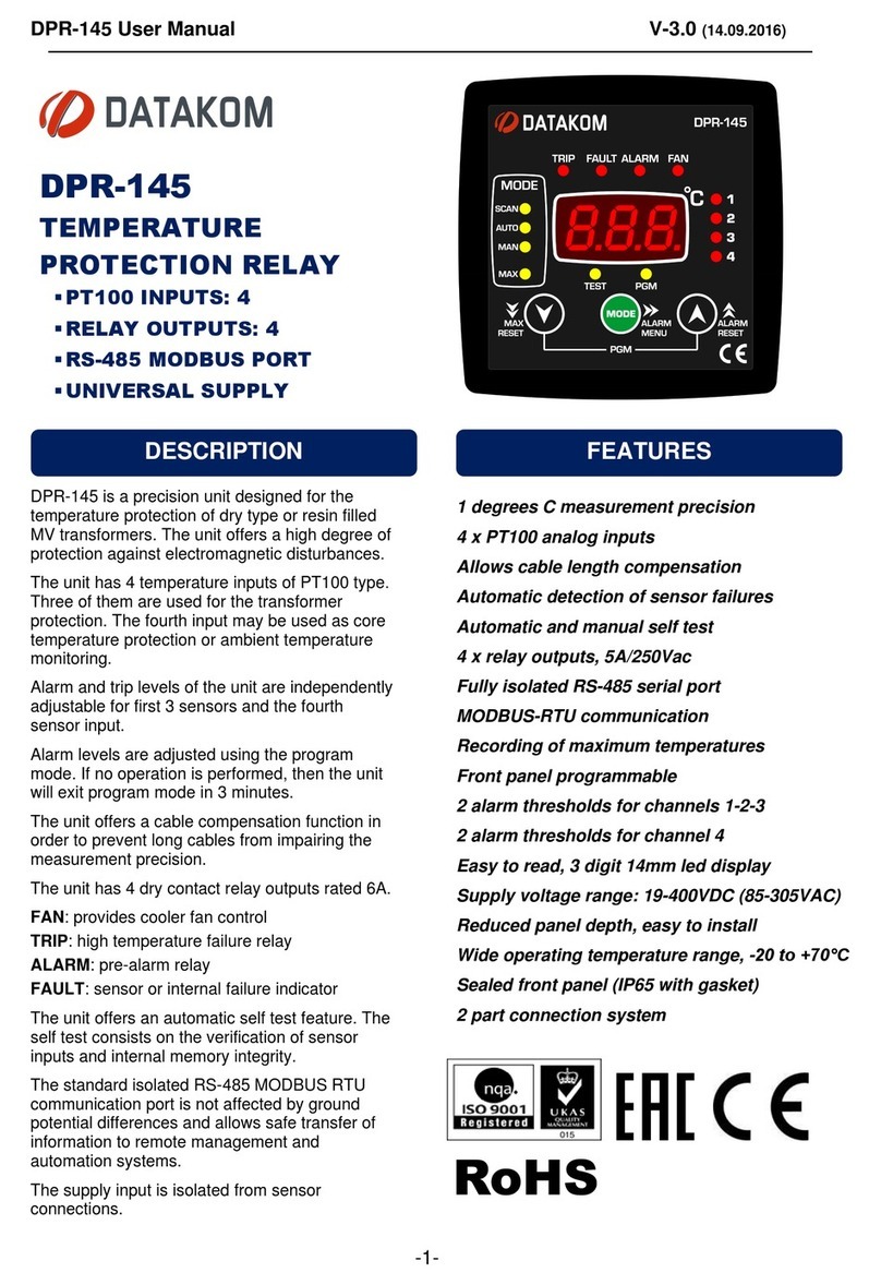
Datakom DPR-400 User manual

DPR-400 User Manual Rev_01 Firmware V-1.0
DPR-400 is a state of the art, color screen,
directional network analyzer and protection relay in
144x144mm standard panel dimensions. Thanks to
its low depth, it saves space in the panel. The device
combines high precision, ease of use and versatility
with a reliable and cost-effective design.
The DPR-400 features dual current measurement
circuits, making it a class 0.5% accuracy analyzer,
and a protection relay capable of measuring 50xIn.
The DPR-400 offers various protection curves to
provide precise protection. Multiple protection curves
can be activated simultaneously.
The DPR-400 displays multiple measurements on its
4.3”screen. The large display offers ease of use and
provides abundant information.
The device can connect to various Scada systems
easily via USB, isolated RS-485 and Ethernet ports
for remote monitoring.
Modbus and IEC60870-5-103 protocols are
supported through RS-485 port.
Modbus TCP/IP and IEC61850 protocols are
supported over the Ethernet port.
Parameter configuration is done using the buttons on
the front panel or with the free PC software. The
program connects via USB, RS-485 or optionally
over the Internet. Additionally, firmware updates are
performed through the USB port.
Two of the relay outputs of the device have
connection monitoring capability. These outputs
continually check the integrity of the load circuit, and
raise an alarm if the circuit opens.
DPR-400 stores up to 7 oscillographic records in
COMTRADE format in its 1MB internal memory.
The device meets the security, EMC, vibration, and
environmental standards for industrial products.
DPR-400
PROTECTION RELAY
• 4.3” color graphic display, 480x272 pixels
• Accurate power analyzer (%0.5)
• 4 quadrant energy counters
• Multiple protection curves
• Self-test, internal failure monitoring
• Cold reclosure
• Configurable digital outputs
• Configurable relay outputs
• 3 independent adjustment sets
• Multiple languages
• All parameters front panel adjustable
• 3 level password protection
• Free PC program for setup
• Setup through USB, RS-485, and Ethernet
• 14 x configurable front panel leds
• Manual & Scada driven closing and opening
• Firmware upgrade through USB
• IP65 protection (with optional gasket)
• Low panel depth, only 55mm
• Trip counter, service warning
• IEC Normal, Very, Extreme Inverse
• UK Long Term Inverse,
• IEEE Medium, Very, Extreme Inverse
• US Normal Inverse, Short Time Inverse
ANSI CODE
DESCRIPTION
27
Under Voltage (Ph-Ph / Ph-N)
46
Negative Sequence Overcurrent
46BC
Broken Conductor
47
Negative Sequence Over Voltage
49RMS
Thermal Overload
50,51
Overcurrent
50N/51N
Ground Overcurrent
50BF
Breaker Failure
59
Over Voltage (Ph-Ph / Ph-N)
67
Directional Overcurrent
74CT
CT Supervision
79
Reclosure
81O
High Frequency
81U
Under Frequency
CLP
Cold Load Pickup
DESCRIPTION
PROTECTION FUNCTIONS
PROTECTION CURVES
FEATURES

DPR-400 User Manual Rev_01 Firmware V-1.0
- 2 -
Any unauthorized use or copying of the contents or any part of this document is prohibited. This applies in
particular to trademarks, model denominations, part numbers and drawings.
This document describes the minimum requirements and necessary steps for the successful installation
of the DPR-400 family units.
Follow the advice given in the document carefully. These are often good practices for the installation of
the units which reduce future issues.
For all technical queries please contact Datakom at the e-mail address below:
technical.support@datakom.com.tr
If additional information to this manual is required, please contact the manufacturer directly at the e-mail
address below: technical.support@datakom.com.tr
Please provide the following information in order to receive answers to any question:
- Device model name (see the back panel of the unit),
- Complete serial number (see the back panel of the unit),
- Firmware version (read from the display screen),
- Measuring-circuit voltage and power supply voltage,
- Precise description of the query.
FILENAME
DESCRIPTION
Rainbow Installation
Rainbow Plus Installation Guide
Rainbow Usage
Rainbow Plus Usage Guide
Rainbow Scada Installation
Rainbow Scada Installation Guide
Rainbow Scada Usage
Rainbow Scada Usage Guide
COPYRIGHT NOTICE
ABOUT THIS DOCUMENT
QUERRIES
RELATED DOCUMENTS

DPR-400 User Manual Rev_01 Firmware V-1.0
- 3 -
REVISION
DATE
AUTHOR
DESCRIPTION
01
06.06.2020
MH
First Edition
CAUTION: Potential risk of injury or death.
WARNING: Potential risk of malfunction or material damage.
ATTENTION: Useful hints for the understanding of device operation.
REVISION HISTORY
TERMINOLOGY

DPR-400 User Manual Rev_01 Firmware V-1.0
- 4 -
The DPR-400 family units are available in various options and peripheral features. Please use below
information for ordering the correct version.
DPR-400
-G
-T
-00
Screw type bracket
Stock Code=J10P01 (per unit)
Self-Retaining type bracket
Stock Code=K16P01 (per unit)
Sealing Gasket, Stock Code= K63P01
ORDERING CODES
SPARE PARTS
Variant
00: Standard Unit
01...99: customer
specific products
Family Code
With Sealing
Gasket
With Conformal
Coating

DPR-400 User Manual Rev_01 Firmware V-1.0
- 5 -
▪Electrical equipment should only be installed by a qualified
specialist. No responsibility is assured by the manufacturer or
any of its subsidiaries for any consequences resulting from the
non-compliance to these instructions.
▪Check the unit for cracks and damages due to transportation.
Do not install damaged equipment.
▪Do not open the unit. There are no serviceable parts inside.
▪Fuses must be connected to the power supply and phase
voltage inputs, in close proximity of the unit.
▪Fuses must be of fast type (FF) with a maximum rating of 6A.
▪Disconnect all power before working on the equipment.
▪When the unit is connected to the network, do not touch the
terminals.
▪Short circuit terminals of unused current transformers.
▪Any electrical parameter applied to the device must be in the
range specified in the user manual. Although the unit is
designed with a wide safety margin, over-range parameters may
reduce lifetime, alter operation precision or even damage the
unit.
▪Do not try to clean the device with solvent or the like. Only
clean with a damp cloth.
▪Verify correct terminal connections before applying power.
▪Only for front panel mounting.
SAFETY NOTICE
Failure to follow below instructions will result in
death or serious injury.

DPR-400 User Manual Rev_01 Firmware V-1.0
- 6 -
1. INSTALLATION INSTRUCTIONS
2. MOUNTING
2.1 DIMENSIONS
2.2 SEALING GASKET
2.3 ELECTRICAL INSTALLATION
3. TERMINAL TECHNICAL SPECIFICATIONS
3.1. BATTERY VOLTAGE INPUT
3.2. AC VOLTAGE INPUTS
3.3. AC CURRENT INPUTS
3.4. DIGITAL INPUTS
3.5. RELAY OUTPUTS
3.6. RS-485 PORT
3.7. USB PORT
3.8. ETHERNET PORT (OPTIONAL)
3.9. RS-232 PORT (OPTIONAL)
3.10. EXTENSION PORT (OPTIONAL)
4. CONNECTION DIAGRAM
5. TERMINAL DESCRIPTIONS
6. TECHNICAL SPECIFICATIONS
7. DESCRIPTION OF CONTROLS
7.1. FRONT PANEL FUNCTIONALITY
7.2. PUSHBUTTON FUNCTIONS
7.3. MEASURED PARAMETERS
8. DISPLAY SYMBOLS
8.1. AUTOMATIC DISPLAY SCROLL
9. PROTECTION FUNCTIONS
9.1. GENERAL FEATURES
9.2. TIME CALCULATION FOR CURVES
9.3. OVERCURRENT PROTECTION (ANSI 50/51)
9.4. NEGATIVE SEQUENCE OVERCURRENT PROTECTION (ANSI 46)
9.5. DIRECTIONAL OVERCURRENT PROTECTION (ANSI 67)
9.6. BROKEN CONDUCTOR (ANSI 46BC)
9.7. CT SUPERVISION (ANSI 74 CT)
9.8. GROUND OVERCURRENT PROTECTION (ANSI 50N/51N)
9.9. NEGATIVE SEQUENCE OVER VOLTAGE PROTECTION (ANSI 47)
9.10. BREAKER FAILURE (ANSI 50BF)
TABLE OF CONTENTS

DPR-400 User Manual Rev_01 Firmware V-1.0
- 7 -
9.11. AUTOMATIC RECLOSURE (ANSI 79)
9.12. COLD LOAD PICKUP (CLP 50/51)
9.13. THERMAL OVERLOAD (ANSI 49RMS)
9.14. UNDER VOLTAGE PROTECTION (ANSI 27)
9.15. HIGH VOLTAGE PROTECTION (ANSI 59)
9.16. UNDER FREQUENCY PROTECTION (ANSI 81U)
9.17. HIGH FREQUENCY PROTECTION (ANSI 81O)
10. MIMIC DIAGRAM
11. PROGRAMMING
11.1. ENTERING PROGRAM MODE
11.2. NAVIGATING BETWEEN MENUS
11.3. MODIFYING PARAMETER VALUE
11.4. EXITING PROGRAM MODE
12. PROGRAM PARAMETER LIST
12.1. EVENT RECORDS
12.2. CONTROLLER CONFIGURATION GROUP
12.3. TRANSFORMER CONFIGURATION
12.4. OVERCURRENT PROTECTION (ANSI 50/51)
12.5. NEGATIVE SEQUENCE OVERCURRENT PROTECTION (ANSI 46)
12.6. BROKEN CONDUCTOR (ANSI 46BC)
12.7. GROUND OVERCURRENT PROTECTION (ANSI 50N/51N)
12.8. FREQUENCY PROTECTION (ANSI 81)
12.9. THERMAL OVERLOAD PROTECTION (ANSI 49RMS)
12.10. VOLTAGE PROTECTION (ANSI 27/59)
12.11. NEGATIVE SEQUENCE OVER VOLTAGE (ANSI 47)
12.12. COLD LOAD PICKUP
12.13. BREAKER FAILURE (ANSI 50BF)
12.14. AUTOMATIC RECLOSURE (ANSI 79)
12.15. CT SUPERVISION (ANSI 74 CT)
12.16. COMTRADE SETTINGS
12.17. IEC60870-5-103 / MODBUS SETTINGS
12.18. INPUT PARAMETERS
12.19. OUTPUT PAREMETERS
12.20. INPUT STRING SETTINGS
12.21. OUTPUT STRING SETTINGS
12.22. INPUT / OUTPUT MATRIX
12.23. ETHERNET SETTINGS
12.24. DATE & TIME SETTINGS
12.25. COUNTER SETTINGS

DPR-400 User Manual Rev_01 Firmware V-1.0
- 8 -
12.26. PASSWORD CHANGE
12.27. RETURN TO FACTORY PRESET
12.28. SAFE EXIT
13. OSCILLOGRAPHIC (COMTRADE) RECORD SETTINGS
14. MODBUS COMMUNICATIONS
14.1. REQUIRED PARAMETERS FOR RS-485 MODBUS COMMUNICATION
14.2. ETHERNET MODBUS TCP/IP PARAMETERS
14.3. DATA FORMATS
14.4. DATA READING
14.5. DATA WRITING
14.6. CRC CALCULATION
14.7. INTERNAL RECORD STORAGE STRUCTURE
14.8. COMMANDS
14.9. REAL TIME CLOCK (RTC)
14.10. MEASUREMENTS
14.11. FUNCTION ALARM INFORMATION
14.12. DIGITAL OUTPUT INFORMATION
14.13. MATRIX INPUT INFORMATION
15. DECLARATION OF CONFORMITY
16. MAINTENANCE
17. DISPOSAL OF THE UNIT
18. ROHS COMPLIANCE

DPR-400 User Manual Rev_01 Firmware V-1.0
- 9 -
Before installation:
▪Read the user manual carefully, determine the correct connection diagram.
▪Remove all connectors and mounting brackets from the unit, then pass the unit through the
mounting opening.
▪Put mounting brackets and tighten. Do not tighten too much, this may break the enclosure.
▪Make electrical connections with plugs removed from sockets, then place plugs to their sockets.
▪Be sure that adequate cooling is provided.
▪Be sure that the temperature of the environment will not exceed the maximum operating
temperature in any case.
▪Be sure that no water will contact the device.
Below conditions may damage the device:
▪Incorrect connections.
▪Incorrect power supply voltage.
▪Voltage at measuring terminals beyond specified range.
▪Voltage applied to digital inputs over specified range.
▪Current at measuring terminals beyond specified range.
▪Overload or short circuit at relay outputs.
▪Connecting or removing data terminals while the unit is powered up.
▪High voltage applied to communication ports.
▪Ground potential differences at non-isolated communication ports.
▪Excessive vibration, direct installation on vibrating parts.
Below conditions may cause abnormal operation:
▪Power supply voltage below minimum acceptable level.
▪Frequency outside specified limits.
▪Phase order fault.
▪Faulty current transformer input.
▪Incorrect current transformer polarity.
▪Missing grounding.
1. INSTALLATION INSTRUCTIONS

DPR-400 User Manual Rev_01 Firmware V-1.0
- 10 -
Dimensions: 164x164x69mm (6.5”x6.5”x2.7”)
Panel Cutout: 140x140mm minimum (5.52”x5.52”)
Weight: - 630gr (approx.)
2. MOUNTING
2.1. DIMENSIONS

DPR-400 User Manual Rev_01 Firmware V-1.0
- 11 -
Mount theunit on aflat, vertical surface. Before mounting, remove themounting brackets and connectors from
the unit, then pass the unit through the mounting opening.
Place and tighten mounting brackets.
Panel Cutout
Required Panel Depth
The unit is designed for panel mounting. The user
should not be able to access parts of the unit other
than the front panel during normal operation.

DPR-400 User Manual Rev_01 Firmware V-1.0
- 12 -
Two different types of brackets are provided:
Screw type bracket
Self-retaining type bracket
Installation of screw type bracket
Installation of self-retaining type bracket
Do not tighten too much, this may break the unit.

DPR-400 User Manual Rev_01 Firmware V-1.0
- 13 -
The rubber gasket (sold separately) provides a watertight means of mounting the module to the panel.
With the gasket, IEC 60529-IP65 protection is provided. A short definition of IP protection levels is given
below:
1st Digit
0 Not protected
1 Protected against solid foreign objects of 50 mm diameter and greater
2 Protected against solid foreign objects of 12.5 mm diameter and greater
3 Protected against solid foreign objects of 2.5 mm diameter and greater
4 Protected against solid foreign objects of 1.0 mm diameter and greater
5 Protected from the amount of dust that would interfere with normal operation
6 Dust tight
2nd Digit
0 Not protected
1 Protected against vertically falling water drops
2 Protected against vertically falling water drops when enclosure is tilted up to 15 °
3 Protected against water sprayed at an angle up to 60 ° on either side of the vertical
4 Protected against water splashed against the component from any direction
5 Protected against water projected in jets from any direction
6 Protected against water projected in powerful jets from any direction
7 Protected against temporary immersion in water
8 Protected against continuous immersion in water, or as specified by user
2.2. SEALING GASKET
Panel
Gasket
Module

DPR-400 User Manual Rev_01 Firmware V-1.0
- 14 -
Although the unit is protected against electromagnetic disturbance, excessive disturbance can affect the
operation, measurement precision and data communication quality.
▪ALWAYS remove plug connectors when inserting wires with a screwdriver.
▪Fuses must be connected to the power supply and phase voltage inputs, in
close proximity to the unit.
▪Fuses must be of fast type with a maximum rating of 6A.
▪Use cables of appropriate temperature range.
▪Use adequate cable section, at least 0.75mm2 (AWG18).
▪Follow national rules for electrical installation.
▪Current transformers must have 1A or 5A output.
▪For current transformer inputs, use at least 1.5mm2section (AWG15) cable.
▪The current transformer cable length should not exceed 1.5 meters. If a
longer cable is used, increase the cable section proportionally.
2.3. ELECTRICAL INSTALLATION
Do not install the unit close to high electromagnetic
noise emitting devices like contactors, high current
busbars, switch mode power supplies, etc.
For the correct storage of event records, adjust the
real time clock through the programming menu.

DPR-400 User Manual Rev_01 Firmware V-1.0
- 15 -
Power Supply Voltage:
19 - 150VDC
Reverse Voltage:
Protected
Maximum Input Current:
200mA @ 24VDC. (All options included, relays engaged.)
50mA @ 110VDC. (All options included, relays engaged.)
Typical operating current:
150mA @ 24VDC. (Options not included, relays engaged.)
40mA @ 110VDC. (Options not included, relays engaged.)
Measurement method:
True RMS
Sampling rate:
8192 Hz
Input voltage range:
0 - 100 VAC (phase-neutral)
Measurement range:
5 - 100VAC Ph-N (10 - 170VAC Ph-Ph)
Input impedance:
5.0 M-ohms
Display resolution:
0.1VAC
Accuracy:
0.5% + 1 digit @ 100VAC Ph-N (±0.6VAC Ph-N)
0.5% + 1 digit @ 170VAC Ph-Ph (±1.0VAC Ph-Ph)
Withstanding:
1300V-AC continuous
Frequency range:
30 - 100 Hz
Frequency display
resolution:
0.01 Hz
Frequency accuracy:
0.5% + 1 digit
3. TERMINAL TECHNICAL SPECIFICATIONS
3.1. BATTERY VOLTAGE INPUT
3.2. AC VOLTAGE INPUTS

DPR-400 User Manual Rev_01 Firmware V-1.0
- 16 -
Structure:
Isolated, integrated current transformers
Measurement Method:
True RMS
Sampling Rate:
8192 Hz
CT Secondary Rating:
1 or 5A
CT Range:
5/5 - 30000/5A minimum
Measurement Range:
Measurement inputs: 0.01 - 6A AC
Protection inputs: 0.1 –250 A AC
Display resolution:
0.1A
Accuracy:
0.5% + 1 digit
Isolation:
1000VAC/1minute from all other terminals.
Maximum Current:
20A continuous
Withstanding:
500A for 1sec
SELECTING THE CT RATING AND CABLE SECTION:
The load on a CT must be kept minimum in order to
minimize phase shift effect of the current transformer.
Phase shift in a CT will cause erroneous power and
power factor readings, although the amp readings are
correct.
It is advised CT rating to be selected following this table
for the best measurement accuracy.
SELECTING THE CT ACCURACY CLASS:
The CT accuracy class should be selected in accordance
with the required measurement precision. The accuracy
class of the controller is 0.5%. Thus 0.5% class CTs are
advised for the best result.
CONNECTING THE CTs:
Be sure to connect each CT to the related phase input with the correct polarity. Mixing CTs between
phases will cause faulty power and power factor readings.
Many combinations of incorrect CT connections are possible, so check both the order of the CTs and
their polarity. Reactive power measurement is affected by incorrect CT connections in a similar was as
active power measurement.
3.3. AC CURRENT INPUTS

DPR-400 User Manual Rev_01 Firmware V-1.0
- 17 -
CORRECT CT CONNECTIONS
Suppose that each phase of the utility mains are loaded with 100 kW. The power factor (PF) for the load
is as follows:
kW
kVAr
kVA
pf
Phase L1
100.0
0.0
100
1.00
Phase L2
100.0
0.0
100
1.00
Phase L3
100.0
0.0
100
1.00
Total
300.0
0.0
300
1.00
EFFECT OF POLARITY REVERSAL
The utility mains is still loaded with 100 kW on each phase. The load power factor (PF) on Phase L2 will
show -1.00 due to reverse CT polarity.
As a result, total load power displayed will be 100 kW.
Measured values are as follows:
kW
kVAr
kVA
pf
Phase L1
100.0
0.0
100
1.00
Phase L2
-100.0
0.0
100
-1.00
Phase L3
100.0
0.0
100
1.00
Total
100.0
0.0
300
0.33

DPR-400 User Manual Rev_01 Firmware V-1.0
- 18 -
EFFECT OF PHASE SWAPPING
The utility mains is still loaded with 100 kW on each phase. PF in phases L2 and L3 will show -0.50 due
to phase shift between voltages and currents which is caused by CT swapping. As a result, the total
power displayed will be 0 kW. Measured values are as follows:
kW
kVAr
kVA
pf
Phase L1
100.0
0.0
100
1.00
Phase L2
-50.0
86.6
100
-0.50
Phase L3
-50.0
-86.6
100
-0.50
Total
0.0
0.0
300
0.0
Number of Inputs:
4 inputs, all configurable. (16 additional inputs optional)
Input Type:
Optically isolated, digital input
Function Selection:
From list
Contact Type:
Normally open or normally closed (programmable)
Minimum Sensing Duration:
100ms
Active Signal Level:
19-140V-DC
Isolation:
1000VAC, 1 minute
Noise Filtering:
Yes
Number of Relays:
4 relays, all configurable. (16 additional relays optional)
Structure:
Relay output, normally open contact, single common terminal free
contact output.
Circuit Monitoring:
RL-2 and RL-3 outputs only
Max. Switching Current:
5A @250VAC
Max. Switching Voltage:
250VAC
Max. Switching Power:
1250VA
3.4. DIGITAL INPUTS
3.5. RELAY OUTPUTS

DPR-400 User Manual Rev_01 Firmware V-1.0
- 19 -
Structure:
RS-485, isolated.
Connection:
3 wires (A-B-GND). Half duplex.
Baud rate:
2400-115200 baud, selectable.
Data type:
8-bit data, no parity, 1 bit stop
Termination
External 120 ohms required.
Common mode voltage:
-0.5 VDC to +7VDC, internally clamped by transient suppressors.
Max. Distance:
1200m @ 9600 baud (with 120-ohm balanced cable)
200m @ 115200 baud (with 120-ohm balanced cable)
Isolation:
500VAC, 1 minute
Supported protocols:
IEC60870-5-103, Modbus RTU
The RS-485 port provides an effective solution for distant PC connection to enable programming and
monitoring via SCADA software.
RS-485 LINE STRUCTURE
Up to 32 controllers can be connected in parallel in a single RS-485 line. A repeater is required in order to
connect more controllers.
The line must be terminated by 120 ohms on each end.
The cable shield must be grounded at one end only.
A B A B A BA B
120R 120R
3.6. RS-485 PORT
The Modbus register list is available at Datakom
technical support.
There is no termination resistor in the controller.
120 ohm termination resistors must be installed at
each end of the line.

DPR-400 User Manual Rev_01 Firmware V-1.0
- 20 -
Description:
USB 2.0, non-isolated, HID mode
Data transfer rate:
1.5/12 Mbit/s, auto detecting
Connector:
Mini-USB (camera cable)
Cable length:
Max. 6 meters
Function:
FAT32(Comtrade), Modbus, FAT32 for firmware update
(only boot loader mode)
The USB port is designed to provide PC connection with the controller. Programming and monitoring can
be done via RainbowPlus program.
The RainbowPlus program is available for free on www.datakom.com.tr.
The connector type is Mini-USB. The cable type is the commonly available camera cable.
Please refer to the RainbowPlus user manual for more detailed information about monitoring,
programming, and control.
3.7. USB PORT
The USB connection may power-up the device. An
extra power supply is not required for testing.
The RS-485 inputs are inactive while the device is
supplied via USB.
Mini-USB
Connector
Mini-USB
cable
Table of contents
Other Datakom Relay manuals
