manuals.online logo
Brands
  1. Home
  2. •
  3. Brands
  4. •
  5. Pilz
  6. •
  7. Relay
  8. •
  9. Pilz 21398-6NL-06 User manual

Pilz 21398-6NL-06 User manual

This manual suits for next models

1

Other Pilz Relay manuals

Pilz 21165-3FR-06 User manual

Pilz

Pilz 21165-3FR-06 User manual

Pilz PNOZ X3 User manual

Pilz

Pilz PNOZ X3 User manual

Pilz PNOZ 1 Owner's manual

Pilz

Pilz PNOZ 1 Owner's manual

Pilz PNOZELOG Series User manual

Pilz

Pilz PNOZELOG Series User manual

Pilz PNOZ X2C User manual

Pilz

Pilz PNOZ X2C User manual

Pilz PNOZ s3 Series User manual

Pilz

Pilz PNOZ s3 Series User manual

Pilz PNOZ X3 Owner's manual

Pilz

Pilz PNOZ X3 Owner's manual

Pilz PNOZ X6 Quick start guide

Pilz

Pilz PNOZ X6 Quick start guide

Pilz PSEN im1 User manual

Pilz

Pilz PSEN im1 User manual

Pilz PZE X5 User manual

Pilz

Pilz PZE X5 User manual

Pilz PNOZELOG Series User manual

Pilz

Pilz PNOZELOG Series User manual

Pilz PNOZ s7.1 User manual

Pilz

Pilz PNOZ s7.1 User manual

Pilz PZE X4V User manual

Pilz

Pilz PZE X4V User manual

Pilz PNOZ po3.3p User manual

Pilz

Pilz PNOZ po3.3p User manual

Pilz PNOZ e1vp User manual

Pilz

Pilz PNOZ e1vp User manual

Pilz PNOZSIGMA Series User manual

Pilz

Pilz PNOZSIGMA Series User manual

Pilz PST 4 User manual

Pilz

Pilz PST 4 User manual

Pilz P2HZ X1 User manual

Pilz

Pilz P2HZ X1 User manual

Pilz PNOZ s1 User manual

Pilz

Pilz PNOZ s1 User manual

Pilz PZE x4p User manual

Pilz

Pilz PZE x4p User manual

Pilz PZE X4V8 User manual

Pilz

Pilz PZE X4V8 User manual

Pilz PNOZ X3.1 User manual

Pilz

Pilz PNOZ X3.1 User manual

Pilz S1MS User manual

Pilz

Pilz S1MS User manual

Pilz PNOZ X Series User manual

Pilz

Pilz PNOZ X Series User manual

Popular Relay manuals by other brands

Woodward BU1-DC2 manual

Woodward

Woodward BU1-DC2 manual

ABB SSR32 product manual

ABB

ABB SSR32 product manual

Siemens SIRIUS 3UG4633 operating instructions

Siemens

Siemens SIRIUS 3UG4633 operating instructions

Siemens SIRIUS 3TK2824 A.20 Series Original operating instructions

Siemens

Siemens SIRIUS 3TK2824 A.20 Series Original operating instructions

Shelly Pro Series user manual

Shelly

Shelly Pro Series user manual

GE MVAX 11 Technical manual

GE

GE MVAX 11 Technical manual

ABB RELION REF615R manual

ABB

ABB RELION REF615R manual

Kemo Electronic B197 quick guide

Kemo Electronic

Kemo Electronic B197 quick guide

Seg MRM3 manual

Seg

Seg MRM3 manual

Basler BE1-700C manual

Basler

Basler BE1-700C manual

CD Automation REVEX 2PH 280A user manual

CD Automation

CD Automation REVEX 2PH 280A user manual

ABB SPAJ 142 C User manual and technical description

ABB

ABB SPAJ 142 C User manual and technical description

Ruelco 1S04 Operation manual

Ruelco

Ruelco 1S04 Operation manual

Basler V3E Z1P B2C1F instruction manual

Basler

Basler V3E Z1P B2C1F instruction manual

GE DGP instruction manual

GE

GE DGP instruction manual

Kyongbo Electronics GDR-D01 user manual

Kyongbo Electronics

Kyongbo Electronics GDR-D01 user manual

Eaton easyE4 series Application note

Eaton

Eaton easyE4 series Application note

Siemens BD2-AK03X/FS Series installation instructions

Siemens

Siemens BD2-AK03X/FS Series installation instructions

manuals.online logo
manuals.online logoBrands
  • About & Mission
  • Contact us
  • Privacy Policy
  • Terms and Conditions

Copyright 2025 Manuals.Online. All Rights Reserved.

21398-6NL-06
PNOZ s6
- 1 -
4D Betriebsanleitung
4GB Operating instructions
4F Manuel d'utilisation
4E Instrucciones de uso
4I Istruzioni per l`uso
4NL Gebruiksaan ijzing
21398-6NL-06PNOZ s6
Sicherheitsschaltgerät PNOZ s6
119758731
Das Zweihandbediengerät erfüllt die Anforde-
rungen nach EN 574 Typ IIIC. Es zwingt den
Bediener die Hände während der gefahrbrin-
genden Bewegung außerhalb der Gefahren-
stelle zu halten. Das Gerät ist zum Einbau in
Steuerungen für Pressen der Metallbearbeitung
als Baustein der Gleichzeitigkeit geeignet.
Es kann eingesetzt werden in Anwendungen
mit
mechanischen Pressen (EN 692)
hydraulischen Pressen (EN 693)
Sicherheitsstromkreisen nach EN 60204-1
PNOZ s6 safety relay
The two-hand control relay meets the require-
ments of EN 574 Type IIIC. It forces the opera-
tor to keep his hands outside the danger zone
area during the hazardous movement. The unit
is suitable for use on controllers for metalwork-
ing presses as a component for simultaneous
switching.
It can be used in applications with
Mechanical presses (EN 692)
Hydraulic presses (EN 693)
Safety circuits in accordance with
EN 60204-1
Bloc logique de sécurité PNOZ s6
Le relais de commande bimanuelle satisfait aux
exigences du type IIIC selon la norme EN 574.
Pendant le mouvement dangereux, le relais
oblige l'opérateur à avoir les deux mains si-
tuées en dehors de la zone de danger. Le relais
de commande bimanuelle est spécialement
adapté pour la gestion de simultanéité des
presses à métaux.
Il peut être utilisé dans des applications avec
des
presses mécaniques (EN 692)
presses hydrauliques (EN 693)
circuits de commande de sécurité selon
EN 60204-1
Zu Ihrer Sicherheit
547263243
Installieren und nehmen Sie das Gerät nur
dann in Betrieb, wenn Sie diese Betriebsan-
leitung gelesen und verstanden haben und
Sie mit den geltenden Vorschriften über Ar-
beitssicherheit und Unfallverhütung vertraut
sind.
Beachten Sie die VDE- sowie die örtlichen
Vorschriften, insbesondere hinsichtlich
Schutzmaßnahmen
Durch Öffnen des Gehäuses oder eigen-
mächtige Umbauten erlischt jegliche Ge-
währleistung.
643523467
Die Zweihandschaltung und die vor- und
nachgeschalteten Teile der Pressenssteue-
rung müssen den einschlägigen VDE-Be-
stimmungen und den Sicherheitsregeln
EN 574, EN 692 und EN 693 entsprechen.
Verlegen Sie die Verbindungskabel zwischen
dem Zweihandbediengerät und den Tastern
nicht unmittelbar neben Starkstromleitun-
gen; es können sonst induktive und kapaziti-
ve Störeinkopplungen entstehen.
Verwenden Sie wegen der geringen Ströme
Tasterkontakte mit Goldauflage.
For your safety
Only install and commission the unit if you
have read and understood these operating
instructions and are familiar with the applica-
ble regulations for health and safety at work
and accident prevention.
Ensure VDE and local regulations are met,
especially those relating to safety.
Any guarantee is rendered invalid if the hous-
ing is opened or unauthorised modifications
are carried out.
The two-hand circuit and the connected
parts of the press control must conform to
the relevant safety standards EN 574,
EN 692 and EN 693
To avoid inductive and capacitance cou-
pling, the cables between the two-hand relay
and the pushbuttons must be run separately
to any power cables.
On account of the low currents you should
use gold-plated pushbutton contacts.
Pour votre sécurité
Vous n'installerez l'appareil et ne le mettrez
en service qu'après avoir lu et compris le
présent manuel d'utilisation et vous être fa-
miliarisé avec les prescriptions en vigueur
sur la sécurité du travail et la prévention des
accidents.
Respectez les normes locales ou VDE, parti-
culièrement en ce qui concerne la sécurité.
L'ouverture de l'appareil ou sa modification
annule automatiquement la garantie.
La commande bimanuelle ainsi que les com-
posants placées en amont et en aval de la
commande de la presse doivent répondre
aux normes VDE en vigueur et aux règles de
sécurité EN 574, EN 692 et EN 693
Pour éviter des interférences inductives ou
capacitives, il est préférable de placer le câ-
ble reliant le relais de commande bimanuelle
et les boutons à l'écart des câbles de puis-
sance.
En raison des courants faibles, veuillez utili-
ser des contacts recouverts d'or.
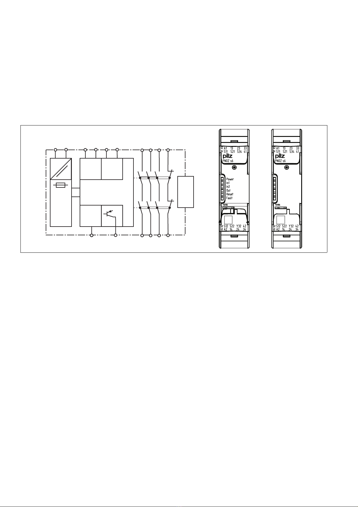
Gerätemerkmale
643526027
Relaisausgänge zwangsgeführt:
– 3 Sicherheitskontakte (S) unverzögert
– 1 Hilfskontakt (Ö) unverzögert
1 Halbleiterausgang
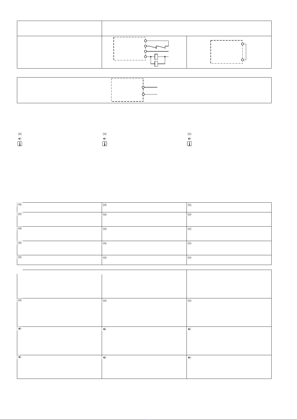
Anschlussmöglichkeiten für:
– 2 Bedienelemente (Taster)
1 Kontakterweiterungsblock PNOZsigma
über Verbindungsstecker anschließbar
LED-Anzeige für:
– Versorgungsspannung
– Eingangszustand Kanal 1
– Eingangszustand Kanal 2
– Schaltzustand Sicherheitskontakte
– Rückführkreis
–Fehler
steckbare Anschlussklemmen (wahlweise
Federkraftklemme oder Schraubklemme)
Unit features
Positive-guided relay outputs:
– 3 safety contacts (N/O), instantaneous
– 1 auxiliary contact (N/C), instantaneous
1 semiconductor output
Connection options for:
– 2 operator elements (buttons)
A connector can be used to connect 1
PNOZsigma contact expansion module
LED indicator for:
– Supply voltage
– Input status, channel 1
– Input status, channel 2
– Switch status, safety contacts
– Feedback circuit
–Error
Plug-in connection terminals (either spring-
loaded terminal or screw terminal)
Caractéristiques de l'appareil
Sorties de relais à contact lié :
– 3 contacts de sécurité (F) instantanés
– 1 contact d'information (O) instantané
1 sortie statique
Raccordements possibles pour :
– 2 éléments de commande (poussoir)
1 bloc d'extension de contacts PNOZsigma
raccordable par connecteur
LED de visualisation pour :
– tension d'alimentation
– état d'entrée canal 1
– état d'entrée canal 2
– état de commutation des contacts de sé-
curité
–bouclederetour
– erreurs
borniers débrochables (au choix avec rac-
cordement à ressort ou à vis)
- 2 -
Sicherheitseigenschaften
117484683
Das Zweihandbediengerät erfüllt folgende Si-
cherheitsanforderungen:
Die Schaltung ist redundant mit Selbstüber-
wachung aufgebaut
Die Sicherheitseinrichtung bleibt auch bei
Ausfall eines Bauteils wirksam
Die Schaltung verhindert einen weiteren
Pressenhub bei
– Relaisversagen
– Verschweißen eines Kontaktes
– Spulendefekt eines Relais
–Leiterbruch
– Kurzschluss
114378891
Das Gerät hat eine elektronische Sicherung.
Safety features
The two-hand control relay meets the following
safety requirements:
The circuit is redundant with built-in self-
monitoring
The safety function remains effective in the
case of a component failure
The circuit prevents a further press stroke in
the case of:
– Relay failure
– Contact welding
– Coil defect on a relay
– Open circuit
– Short circuit
The unit has an electronic fuse.
Caractéristiques de sécurité
Le relais de commande bimanuelle satisfait aux
exigences de sécurité suivantes :
La conception interne est redondante avec
une autosurveillance
La sécurité reste garantie, même en cas de
défaillance d'un composant
La conception interne empêche un nouveau
cycle de la presse en cas de
– dysfonctionnement du relais
– soudage d'un contact
– défaut sur la bobine d'un relais interne
– rupture de câble
–court-circuit
L'appareil est équipé d'une sécurité électro-
nique.
Blockschaltbild/Klemmenbelegung Block diagram/terminal configuration Schéma de principe/affectation des
bornes
*nur bei UB = 48 – 240 V AC/DC *only with UB = 48 – 240 VAC/DC * uniquement lorsque UB = 48 – 240 V AC/DC
566336011
Mitte: Frontansicht mit Abdeckung
Rechts: Frontansicht ohne Abdeckung
Centre: Front view with cover
Right: Front view without cover
Schéma du milieu : vue frontale avec capot de
protection
A droite : vue frontale sans capot de protection
Funktionsbeschreibung
117480075
Das Zweihandbediengerät muss durch
gleichzeitiges Betätigen von zwei Tastern in-
nerhalb von 0,5 s aktiviert werden. Es unter-
bricht bei Loslassen eines oder beider Taster
den Steuerbefehl für die gefährliche Bewe-
gung.
Wieder aktivieren: Die Ausgangsrelais spre-
chen erst dann wieder an, wenn beide Bedie-
nelemente losgelassen und erneut
gleichzeitig betätigt werden.
Function description
The two-hand control relay must be activat-
ed by simultaneously pressing two buttons
within 0,5 s. If one or both of the buttons are
released, the unit interrupts the control com-
mand for the hazardous movement.
Reactivation: The output relays will not re-
energise until both operator elements have
been released and then re-operated simulta-
neously.
Description du fonctionnement
Le relais de commande bimanuelle doit être
activé par l'appui simultané de deux boutons
pendant 0,5 s. Il interrompt l'ordre de com-
mande du mouvement dangereux lorsque
l'un des deux boutons ou les deux boutons
sont relâchés.
Réactivation : Les relais de sortie ne peuvent
être réenclenchés que lorsque les deux élé-
ments de commande ont été relâchés puis
de nouveau actionnés ensemble.
InputInput
A1 A2 S21 S22
=
Po er
Feed-
back
(Reset)
S34
S11 S12
=
Y32
(~)*
K1
K2
13 23 33
24 34
14
41
42
Interface
expansion
unit
( )*
- 3 -
Montage
419461003
Grundgerät ohne Kontakterweiterungs-
block montieren:
Stellen Sie sicher, dass der Abschluss-
stecker seitlich am Gerät gesteckt ist.
Grundgerät und Kontakterweiterungsblock
PNOZsigma verbinden:
Entfernen Sie den Abschlussstecker seitlich
am Grundgerät und am Kontakterweite-
rungsblock.
Verbinden Sie das Grundgerät und den Kon-
takterweiterungsblock mit dem mitgeliefer-
ten Verbindungsstecker bevor Sie die Geräte
auf der Normschiene montieren.
Montage im Schaltschrank
Montieren Sie das Sicherheitsschaltgerät in
einen Schaltschrank mit einer Schutzart von
mindestens IP54.
Befestigen Sie das Gerät mit Hilfe des Rast-
elements auf der Rückseite auf einer Norm-
schiene (35 mm).
Bei senkrechter Einbaulage: Sichern Sie das
Gerät durch ein Halteelement (z. B. Endhalter
oder Endwinkel).
Vor dem Abheben von der Normschiene das
Gerät nach oben oder unten schieben.
Installation
Install base unit without contact expander
module:
Ensure that the plug terminator is inserted at
the side of the unit.
Connect base unit and PNOZsigma contact
expander module:
Remove the plug terminator at the side of the
base unit and at the contact expander mod-
ule.
Connect the base unit and the contact ex-
pander module to the supplied connector
before mounting the units to the DIN rail.
Installation in control cabinet
The safety relay should be installed in a con-
trol cabinet with a protection type of at least
IP54.
Use the notch on the rear of the unit to attach
it to a DIN rail (35 mm).
When installed vertically: Secure the unit by
using a fixing element (e.g. retaining bracket
or end angle).
Push the unit upwards or downwards before
lifting it from the DIN rail.
Montage
Installer l'appareil de base sans bloc d'ex-
tension de contacts :
Assurez-vous que la fiche de terminaison est
insérée sur le côté de l'appareil.
Raccorder l'appareil de base et le bloc d'ex-
tension de contacts PNOZsigma :
Retirez la fiche de terminaison sur le côté de
l'appareil de base et sur le bloc d'extension
de contacts.
Avant de monter les appareils sur le rail DIN,
reliez l'appareil de base et le bloc d'exten-
sion de contacts à l'aide du connecteur four-
ni.
Montage dans une armoire
Montez le bloc logique de sécurité dans une
armoire électrique ayant un indice de protec-
tion d'au moins IP54.
Montez l'appareil sur un rail DIN à l'aide du
système de fixation situé sur la face arrière
(35 mm).
Si l'appareil est monté à la verticale : sécuri-
sez-le à l'aide d'un élément de maintien
(exemple : support terminal ou équerre termi-
nale).
Avant de retirer l'appareil du rail DIN, pous-
sez l'appareil vers le haut ou vers le bas.
Verdrahtung
117588491
Beachten Sie:
Angaben im Abschnitt „Technische Daten“
unbedingt einhalten.
Die Ausgänge 13-14, 23-24, 33-34 sind Si-
cherheitskontakte, der Ausgang 41-42 ist ein
Hilfskontakt (z. B. für Anzeige).
Vor die Ausgangskontakte eine Sicherung
(s. techn. Daten) schalten, um das Ver-
schweißen der Kontakte zu verhindern.
Berechnung der max. Leitungslänge Imax im
Eingangskreis:
Rlmax = max. Gesamtleitungswiderstand
(s. techn. Daten)
Rl/ km = Leitungswiderstand/km
Leitungsmaterial aus Kupferdraht mit einer
Temperaturbeständigkeit von 60/75 °C ver-
wenden.
Sorgen Sie an allen Ausgangskontakten bei
kapazitiven und induktiven Lasten für eine
ausreichende Schutzbeschaltung.
Wiring
Please note:
Information given in the “Technical details”
must be followed.
Outputs 13-14, 23-24, 33-34 are safety con-
tacts, output 41-42 is an auxiliary contact
(e.g. for display).
To prevent contact welding, a fuse should be
connected before the output contacts (see
technical details).
Calculation of the max. cable runs lmax in the
input circuit:
Rlmax = max. overall cable resistance (see
technical details)
Rl/km = cable resistance/km
Use copper wire that can withstand
60/75 °C.
Sufficient fuse protection must be provided
on all output contacts with capacitive and in-
ductive loads.
Raccordement
Important :
Respectez impérativement les données indi-
quées dans la partie "Caractéristiques tech-
niques".
Les sorties 13-14, 23-24, 33-34 sont des
contacts de sécurité, la sortie 41-42 est un
contact d'information (par exemple pour l'af-
fichage).
Protection des contacts de sortie par des fu-
sibles (voir les caractéristiques techniques)
pour éviter leur soudage.
Calcul de la longueur de câble max. Imax sur
le circuit d'entrée :
Rlmax = résistance max. de l'ensemble du
câblage (voir les caractéristiques techni-
ques)
Rl/km = résistance du câblage/km
Utilisez uniquement des fils de câblage en
cuivre résistant à des températures de
60/75 °C.
Assurez-vous du pouvoir de coupure des
contacts de sortie en cas de charges capaci-
tives ou inductives.
Betriebsbereitschaft herstellen Preparing for operation Mettre l'appareil en mode de marche
Anschluss Connection Connexion
Versorgungsspannung Supply voltage Tension d'alimentation
Versorgungsspannung/power supply/tension
d'alimentation
AC DC
Eingangskreis Input circuit Circuit d'entrée
Eingangskreis/input circuit/circuit d'entrée Einkanalig/single-channel /monocanal Zweikanalig/dual-channel/à deux canaux
Zweihandtaster
mit Querschlusserkennung/
two-hand button
with detection of shorts across contacts/
poussoir de commande bimanuelle
avec détection des courts-circuits entre les
canaux
Rlmax
Rl / km
Imax =
Rlmax
Rl / km
Imax =
Rlmax
Rl / km
Imax =
A1 L
A2 N
S22
A1 L+
A2 L-
S12(+)
S11
S21
S22(-)
S1
S2
- 4 -
Rückführkreis Feedback loop Boucle de retour
Rückführkreis/
feedback loop/
boucle de retour
Rückführkreis/feedback loop/ Boucle de retour
Halbleiterausgang Semiconductor output Sortie statique
Betrieb
557883787
Das Gerät ist betriebsbereit, wenn die LED Po-
wer permanent leuchtet.
LEDs zeigen den Status und Fehler während
des Betriebs an:
LED leuchtet
LED blinkt
552061195
INFO
Statusanzeigen und Fehleranzeigen kön-
nen unabhängig voneinander auftreten. Bei
einer Fehleranzeige leuchtet oder blinkt die
LED "Fault" (Ausnahme: "Versorgungs-
spannung zu gering"). Eine zusätzlich blin-
kende LED weist auf eine mögliche
Fehlerursache hin. Eine zusätzlich statisch
leuchtende LED weist auf einen normalen
Betriebszustand hin. Es können mehrere
Statusanzeigen und Fehleranzeigen gleich-
zeitig auftreten.
Operation
The unit is ready for operation when the Power
LED is permanently lit.
LEDs indicate the status and errors during op-
eration:
LED on
LED flashes
INFORMATION
Status indicators and error indicators may
occur independently. In the case of an error
display, the "Fault" LED will light or flash
(exception: "Supply voltage too low"). An
LED that is also flashing indicates the po-
tential cause of the error. An LED that is lit
and is static indicates a normal operating
status. Several status indicators and error
indicators may occur simultaneously.
Utilisation
L'appareil est prêt à fonctionner lorsque la LED
Power reste allumée en permanence.
Les LEDs indiquent l'état et les erreurs lors du
fonctionnement:
LED allumée
LED clignotante
INFORMATION
L'affichage de l'état et des erreurs peut sur-
venir indépendamment. Lors de l'affichage
d'une erreur, la LED "Fault" s'allume ou cli-
gnote (exception : "Tension d'alimentation
trop faible"). Une LED clignotante supplé-
mentaire informe sur une cause possible
d'erreur. Une LED supplémentaire qui s'al-
lume de façon permanente informe de l'état
normal de fonctionnement. Plusieurs affi-
chages de l'état et des erreurs peuvent sur-
venir en même temps.
Statusanzeigen Status indicators Affichages d'état
551604875
Power
Versorgungsspannung liegt an. Power
Supply voltage is present.
Power
la tension d'alimentation est présente.
690876043
In1
Taster an S11 ist betätigt. In1
Pushbutton on S11 is operated.
In1
Le poussoir sur S11 est actionné.
690878731
In2
Taster an S21 ist betätigt. In2
Pushbutton on S21 is operated.
In2
Le poussoir sur S21 est actionné.
551611787
Out
Sicherheitskontakte sind geschlossen und
Halbleiterausgang Y32 führt High-Signal.
Out
Safety contacts are closed and semicon-
ductor output Y32 carries a high signal.
Out
Les contacts de sécurité sont fermés et la
sortie statique Y32 délivre un niveau haut.
551614091
Reset
An S34 liegt 24 V DC an. Reset
24 VDC is present at S34.
Réarmement
24 V DC sur S34.
Fehleranzeigen Error indicators Affichage des erreurs
551771659
Alle LEDs aus
Diagnose: Querschluss/Erdschluss; Gerät
ausgeschaltet
Abhilfe: Querschluss/Erdschluss behe-
ben, Versorgungsspannung für 1 Min.
ausschalten.
All LEDs off
Diagnostics: Short across contacts/earth
fault; unit switched off
Remedy: Rectify short across contacts/
earth fault, switch off supply voltage for 1
min.
Toutes les LEDs sont éteintes
Diagnostic : court-circuit/mise à la terre ;
appareil éteint
Remède : supprimer le court-circuit/la
mise à la terre, couper la tension d'ali-
mentation pendant 1 min.
551773963
Fault
Diagnose: Abschlussstecker nicht gesteckt
Abhilfe: Abschlussstecker stecken, Ver-
sorgungsspannung aus- und wieder ein-
schalten.
Fault
Diagnostics: Plug terminator not connected
Remedy: Insert plug terminator, switch
supply voltage off and then on again.
Fault
Diagnostic : fiche de terminaison non bran-
chée
Remède : brancher la fiche de terminai-
son, couper puis remettre en marche la
tension d'alimentation
551776267
Fault
Diagnose: Interner Fehler, Gerät defekt
Abhilfe: Versorgungsspannung aus- und
wieder einschalten, gegebenenfalls Ge-
rät tauschen.
Fault
Diagnostics: Internal error, unit defective
Remedy: Switch supply voltage off and
then on again, change unit if necessary.
Fault
Diagnostic : erreur interne, appareil défec-
tueux
Remède : couper puis remettre en mar-
che la tension d'alimentation, si besoin
échanger l'appareil
551778571
Power
Diagnose: Versorgungsspannung zu gering
Abhilfe: Versorgungsspannung überprü-
fen.
Power
Diagnostics: Supply voltage too low
Remedy: Check the supply voltage.
Power
Diagnostic : tension d'alimentation trop fai-
ble
Remède : vérifier la tension d'alimenta-
tion
K5 K6
K5 L1
N
K6
S12
13 (23,33)
S34
14 (24,34)
S12
S34
Y32 PLC Input
S22 Gnd
- 5 -
691021835
In1, In2 wechselweise
Fault
Diagnose: Anschlussfehler oder Quer-
schluss zwischen S12 und S22 erkannt
oder interner Fehler
Abhilfe: Anschlussfehler beheben oder
Querschluss beheben, Versorgungs-
spannung aus- und wieder einschalten.
In1, In2 alternately
Fault
Diagnostics: Connection error or short be-
tween S12 and S22 detected or internal er-
ror
Remedy: Rectify connection error or
short across contacts, switch supply
voltage off and then on again.
In1, In2 alternativement
Fault
Diagnostic : détection d'une erreur de rac-
cordement ou d'un court-circuit entre S12
et S22 ou erreur interne
Remède : supprimer l'erreur de raccor-
dement ou le court-circuit, couper puis
remettre en marche la tension d'alimen-
tation.
691024139
In1
Fault
Diagnose: Gleichzeitigkeitsüberschrei-
tung: Kanal 1 zu spät oder Einschaltblocka-
de wegen Kurzzeitunterbrechung an S11;
Eingangskreise nicht gleichzeitig betätigt
Abhilfe: Beide Eingangskreise, S12 und
S22 gleichzeitig öffnen und wieder
schließen.
In1
Fault
Diagnostics: Simultaneity exceeded: Chan-
nel 1 too late or power-up blocked due to
short-term interruption at S11; input cir-
cuits not operated simultaneously
Remedy: Open both input circuits, S12
and S22, simultaneously and then close
again.
In1
Fault
Diagnostic : dépassement de la
simultanéité : canal 1 en retard ou blocage
du relais à cause d'une coupure aléatoire
sur S11 ; les circuits d'entrée ne sont pas
actionnés simultanément
Remède : ouvrir ensemble les deux cir-
cuits d'entrée S12 et S22 puis les refer-
mer.
691026443
In2
Fault
Diagnose: Gleichzeitigkeitsüberschrei-
tung: Kanal 2 zu spät oder Einschaltblocka-
de wegen Kurzzeitunterbrechung an S21;
Eingangskreise nicht gleichzeitig betätigt
Abhilfe: Beide Eingangskreise, S12 und
S22 gleichzeitig öffnen und wieder
schließen.
In2
Fault
Diagnostics: Simultaneity exceeded: Chan-
nel 2 too late or power-up blocked due to
short-term interruption at S21; input cir-
cuits not operated simultaneously
Remedy: Open both input circuits, S12
and S22, simultaneously and then close
again.
In2
Fault
Diagnostic : dépassement de la
simultanéité : canal 2 en retard ou blocage
du relais à cause d'une coupure aléatoire
sur S21 ; les circuits d'entrée ne sont pas
actionnés simultanément
Remède : ouvrir ensemble les deux cir-
cuits d'entrée S12 et S22 puis les refer-
mer.
Fehler - Störungen
551266315
Fehlfunktionen der Kontakte: Bei ver-
schweißten Kontakten ist nach Öffnen des
Eingangskreises keine neue Aktivierung
möglich.
Faults - malfunctions
Contact malfunctions: If the contacts have
welded, reactivation will not be possible after
the input circuit has opened.
Erreurs – Défaillances
Défaut de fonctionnement des contacts de
sortie : si les contacts sont soudés, un réar-
mement est impossible après ouverture du
circuit d'entrée.
- 6 -
Technische Daten Technical details Caractéristiques techniques
Elektrische Daten Electrical data Données électriques
Versorgungsspannung Supply voltage tension d'alimentation
Versorgungsspannung UBDC Supply voltage UBDC Tension d'alimentation UBDC 24 V
Versorgungsspannung UBAC/DC Supply voltage UBAC/DC Tension d'alimentation UBAC/DC 48 - 240 V
Spannungstoleranz Voltage tolerance Plage de la tension d'alimentation -15 %/+10 %
Leistungsaufnahme bei UBAC Power consumption at UBAC Consommation UBAC 7,0 VA No. 750136, 751136
Leistungsaufnahme bei UBDC Power consumption at UBDC Consommation UBDC 3,5 W
Frequenzbereich AC Frequency range AC Plage de fréquences AC 50 - 60 Hz
Restwelligkeit DC Residual ripple DC Ondulation résiduelle DC 20 %
Spannung und Strom an Voltage and current at Tension et courant sur
Eingangskreis DC: 24,0 V Input circuit DC: 24,0 V circuit d'entrée DC : 24,0 V
Schließer N/O contact Contact à fermeture 20 mA
Öffner N/C contact Contact à ouverture 10 mA
Rückführkreis DC: 24,0 V Feedback loop DC: 24,0 V boucle de retour DC : 24,0 V 15,0 mA
Anzahl der Ausgangskontakte Number of output contacts Nombre de contacts de sortie
Sicherheitskontakte (S)
unverzögert:
Safety contacts (S) instantaneous: Contacts de sécurité (F)
instantanés :
3
Hilfskontakte (Ö): Auxiliary contacts (N/C): Contacts d'information (O) : 1
Typ nach EN 574 Type in accordance with EN 574 Type selon l' EN 574 III C
Gebrauchskategorie nach
EN 60947-4-1
Utilisation category in accordance
with EN 60947-4-1
Catégorie d'utilisation selon
EN 60947-4-1
Sicherheitskontakte: AC1 bei 240 V Safety contacts: AC1 at 240 V Contacts de sécurité : AC1
pour 240 V
Imin:0,01 A , Imax:6,0 A
Pmax: 1500 VA
Sicherheitskontakte: DC1 bei 24 V Safety contacts: DC1 at 24 V Contacts de sécurité : DC1 pour
24 V
Imin: 0,01 A , Imax: 6,0 A
Pmax: 150 W
Hilfskontakte: AC1 bei 240 V Auxiliary contacts: AC1 at 240 V Contacts d'information : AC1
pour 240 V
Imin: 0,01 A , Imax: 6,0 A
Pmax: 1500 VA
Hilfskontakte: DC1 bei 24 V Auxiliary contacts: DC1 at 24 V Contacts d'information : DC1
pour 24 V
Imin: 0,01 A , Imax: 6,0 A
Pmax: 150 W
Gebrauchskategorie nach
EN 60947-5-1
Utilisation category in accordance
with EN 60947-5-1
Catégorie d'utilisation selon
EN 60947-5-1
Sicherheitskontakte: AC15 bei
230 V
Safety contacts: AC15 at 230 V Contacts de sécurité : AC15
pour 230 V
Imax: 3,0 A No. 750136, 751136
5,0 A No. 750106, 751106
Sicherheitskontakte: DC13 bei 24 V
(6 Schaltspiele/min)
Safety contacts: DC13 at 24 V
(6 cycles/min)
Contacts de sécurité : DC13
pour 24 V (6 manœuvres/min)
Imax: 4,0 A No. 750136, 751136
5,0 A No. 750106, 751106
Hilfskontakte: AC15 bei 230 V Auxiliary contacts: AC15 at 230 V Contacts d'information : AC15
pour 230 V
Imax: 3,0 A No. 750136, 751136
5,0 A No. 750106, 751106
Hilfskontakte: DC13 bei 24 V
(6 Schaltspiele/min)
Auxiliary contacts: DC13 at 24 V
(6 cycles/min)
Contacts d'information : DC13
pour 24 V (6 manœuvres/min)
Imax: 4,0 A No. 750136, 751136
5,0 A No. 750106, 751106
Kontaktmaterial Contact material Matériau des contacts AgCuNi + 0,2 µm Au
Kontaktabsicherung, extern
(IK= 1 kA) nach EN 60947-5-1
External contact fuse protection
(IK= 1 kA) to EN 60947-5-1
Protection des contacts en externe
(IK= 1 kA) selon EN 60947-5-1
Schmelzsicherung flink Blow-out fuse, quick Fusible rapide
Sicherheitskontakte: Safety contacts: Contacts de sécurité : 10 A No. 750106, 751106
6 A No. 750136, 751136
Hilfskontakte: Auxiliary contacts: Contacts d'information : 10 A No. 750106, 751106
6 A No. 750136, 751136
Schmelzsicherung träge Blow-out fuse, slow Fusible normal
Sicherheitskontakte: Safety contacts: Contacts de sécurité : 4 A No. 750136, 751136
6 A No. 750106, 751106
Hilfskontakte: Auxiliary contacts: Contacts d'information : 4 A No. 750136, 751136
6 A No. 750106, 751106
Sicherungsautomat 24V AC/DC,
Charakteristik B/C
Circuit breaker 24 VAC/DC, charac-
teristic B/C
Disjoncteur 24 V AC/DC, caractéris-
tique B/C
Sicherheitskontakte: Safety contacts: Contacts de sécurité : 4 A No. 750136, 751136
6 A No. 750106, 751106
Hilfskontakte: Auxiliary contacts: Contacts d'information : 4 A No. 750136, 751136
6 A No. 750106, 751106
Halbleiterausgänge (kurz-
schlussfest)
Semiconductor outputs (short cir-
cuit proof)
Sorties statiques (protégées contre
les courts-circuits)
24,0 V DC, 20 mA
Max. Gesamtleitungswiderstand
Rlmax je Eingangskreis
Max. overall cable resistance
Rlmax per input circuit
Résistance max. de l'ensemble du
câblage Rlmax pour chaque circuit
d'entrée
30 Ohm
- 7 -
Sicherheitstechnische Kennda-
ten
Safety-related characteristic
data
Caractéristiques techniques de
sécurité
PL nach EN ISO 13849-1: 2006 PL in accordance with
EN ISO 13849-1: 2006
PL selon EN ISO 13849-1: 2006
PL e (Cat. 4)
Kategorie nach EN 954-1 Category in accordance with
EN 954-1
Catégorie selon EN 954-1
Cat. 4
SIL CL nach EN IEC 62061 SIL CL in accordance with
EN IEC 62061
SIL CL selon EN IEC 62061
SIL CL 3
PFH nach EN IEC 62061 PFH in accordance with
EN IEC 62061
PFH selon EN IEC 62061
2,62E-09
SIL nach IEC 61511 SIL in accordance with IEC 61511 SIL selon IEC 61511 SIL 3
PFD nach IEC 61511 PFD in accordance with IEC 61511 PFD selon IEC 61511 3,32E-05
TM[Jahr] nach EN ISO 13849-1:
2006
TM[year] in accordance with
EN ISO 13849-1: 2006
TM[année] selon EN ISO 13849-1:
2006
20
Zeiten Times Temporisations
Rückfallverzögerung (Ansprechzeit
nach EN 574)
Delay-on de-energisation (reaction
time in accordance with EN 574)
Temps de retombée (temps d'appel
selon l'EN 574)
Schließer N/O contact Contact à fermeture 30 ms
Öffner N/C contact Contact à ouverture 40 ms
Wiederbereitschaftszeit Recovery time Temps de réinitialisation 250 ms
Gleichzeitigkeit Kanal 1 und 2 Simultaneity, channel 1 and 2 Simultanéité des canaux 1 et 2 0,5 s
Überbrückung bei Spannungsein-
brüchen der Versorgungsspannung
Supply interruption before de-ener-
gisation
Inhibition en cas de micro-coupures
de la tension d'alimentation
20 ms
Umweltdaten Environmental data Données sur l'environnement
EMV EMC CEM EN 60947-5-1, EN 61000-6-2,
EN 61000-6-4
Schwingungen nach EN 60068-2-6 Vibration to EN 60068-2-6 Vibrations selon EN 60068-2-6
Frequenz Frequency Fréquence 10 - 55 Hz
Amplitude Amplitude Amplitude 0,35 mm
Klimabeanspruchung Climatic suitability Sollicitations climatiques EN 60068-2-78
Luft- und Kriechstrecken nach
EN 60947-1
Airgap creepage in accordance
with EN 60947-1
Cheminement et claquage
selon EN 60947-1
Verschmutzungsgrad Pollution degree Niveau d'encrassement 2
Überspannungskategorie Overvoltage category Catégorie de surtensions III
Bemessungsisolationsspannung Rated insulation voltage Tension assignée d'isolement 250 V
Bemessungsstoßspannungsfestig-
keit
Rated impulse withstand voltage Tension assignée de tenue aux
chocs
4,00 kV
Umgebungstemperatur Ambient temperature Température d'utilisation -10 - 55 °C
Lagertemperatur Storage temperature Température de stockage -40 - 85 °C
Schutzart Protection type Indice de protection
Einbauraum (z. B. Schaltschrank) Mounting (e.g. cabinet) Lieu d'implantation (par exemple :
armoire électrique)
IP54
Gehäuse Housing Boîtier IP40
Klemmenbereich Terminals Borniers IP20
Mechanische Daten Mechanical data Données mécaniques
Gehäusematerial Housing material Matériau du boîtier
Gehäuse Housing Boîtier PC
Front Front Face avant PC
Querschnitt des Außenleiters bei
Schraubklemmen
Cross section of external conduc-
tors with screw terminals
Capacité de raccordement des bor-
niers à vis
1 Leiter flexibel 1 core flexible 1 câble flexible 0,25 - 2,50 mm² , 24 - 12 AWG
No. 750106, 750136
2 Leiter gleichen Querschnitts, flexi-
bel:
2 core, same cross section, flexible: 2 câbles flexibles de même
section :
mit Aderendhülse, ohne Kunststoff-
hülse
with crimp connectors, without in-
sulating sleeve
avec embout, sans cosse plastique 0,25 - 1,00 mm² , 24 - 16 AWG
No. 750106, 750136
ohne Aderendhülse oder mit TWIN
Aderendhülse
without crimp connectors or with
TWIN crimp connectors
sans embout ou avec embout TWIN 0,20 - 1,50 mm² , 24 - 16 AWG
No. 750106, 750136
Anzugsdrehmoment bei Schraub-
klemmen
Torque setting with screw terminals Couple de serrage des borniers à
vis
0,50 Nm No. 750106, 750136
Querschnitt des Außenleiters bei
Federkraftklemmen: flexibel mit/
ohne Aderendhülse
Cross section of external conduc-
tors with spring-loaded terminals:
Flexible with/without crimp connec-
tors
Capacité de raccordement des bor-
niers à ressort : flexible avec/sans
embout
0,20 - 2,50 mm² , 24 - 12 AWG
No. 751106, 751136
Federkraftklemmen: Klemmstellen
pro Anschluss
Spring-loaded terminals: Terminal
points per connection
Borniers à ressort : points de rac-
cordement pour chaque borne
2No. 751106, 751136
Abisolierlänge Stripping length Longueur dénudation 9 mm No. 751106, 751136
- 8 -
Abmessungen Dimensions Dimensions
Höhe Height Hauteur 100,0 mm No. 751106, 751136
98,0 mm No. 750106, 750136
Breite Width Largeur 22,5 mm
Tiefe Depth Profondeur 120,0 mm
Gewicht Weight Poids 187 g No. 750106
190 g No. 751106
210 g No. 750136, 751136
No. ist gleichbedeutend mit Bestell-Nr.
1204958603
ACHTUNG!
Beachten Sie unbedingt die Lebensdauer-
kurven der Relais. Die sicherheitstechni-
schen Kennzahlen der Relaisausgänge
gelten nur, solange die Werte der Lebens-
dauerkurven eingehalten werden.
Der PFH-Wert ist abhängig von der Schaltfre-
quenz und der Belastung des Relaisausgan-
ges.
Solange die Lebensdauerkurven nicht erreicht
werden, kann der angegebene PFH-Wert unab-
hängig von der Schaltfrequenz und der Bela-
stung verwendet werden, da der PFH-Wert den
B10d-Wert der Relais sowie die Ausfallraten
der anderen Bauteile bereits berücksichtigt.
1077650443
Alle in einer Sicherheitsfunktion verwendeten
Einheiten müssen bei der Berechnung der Si-
cherheitskennwerte berücksichtigt werden.
585241611
Es gelten die 2011-06 aktuellen Ausgaben der
Normen.
No. stands for order number.
1204958603
CAUTION!
It is essential to consider the relay's service
life graphs. The relay outputs' safety-relat-
ed characteristic data is only valid if the val-
ues in the service life graphs are met.
The PFH value depends on the switching fre-
quency and the load on the relay output.
If the service life graphs are not accessible, the
stated PFH value can be used irrespective of
the switching frequency and the load, as the
PFH value already considers the relay's B10d
value as well as the failure rates of the other
components.
All the units used within a safety function must
be considered when calculating the safety
characteristic data.
The standards current on 2011-06 apply.
No. correspond à la référence du produit.
1204958603
ATTENTION!
Veuillez absolument tenir compte des cour-
bes de durée de vie des relais. Les données
de sécurité des sorties relais sont unique-
ment valables tant que les valeurs des
courbes de durée de vie sont respectées.
La valeur PFH dépend de la fréquence de com-
mutation et de la charge de la sortie relais.
Tant que les courbes de durée de vie ne sont
pas atteintes, la valeur PFH indiquée peut être
utilisée indépendamment de la fréquence de
commutation et de la charge car la valeur PFH
prend déjà en compte la valeur B10d des relais
ainsi que les taux de défaillance des autres
composants.
Toutes les unités utilisées dans une fonction de
sécurité doivent être prises en compte dans le
calcul des caractéristiques de sécurité.
Les versions actuelles 2011-06 des normes
s'appliquent.
Konventioneller thermischer
Strom bei gleichzeitiger Bela-
stung mehrerer Kontakte
Conventional thermal current
while loading several contacts
Courant thermique convention-
nel en cas de charge sur plu-
sieurs contacts
Ith pro Kontakt bei UBDC Ith at UBDC Ith pour UBDC
1 Kontakt 1 contact 1 contact 6,00 A
2 Kontakte 2 contacts 2 contacts 6,00 A
3 Kontakte 3 contacts 3 contacts 4,50 A No. 750136, 751136
6,00 A No. 750106, 751106
Ith pro Kontakt bei UBAC Ith at UBAC Ith pour UBAC
1 Kontakt 1 contact 1 contact 6,00 A No. 750136, 751136
2 Kontakte 2 contacts 2 contacts 6,00 A No. 750136, 751136
3 Kontakte 3 contacts 3 contacts 4,50 A No. 750136, 751136
Mechanische Daten Mechanical data Données mécaniques
- 9 -
Lebensdauerkurve der Ausgangsrelais
1196936075
Die Lebensdauerkurven geben an, ab welcher
Schaltspielzahl mit verschleißbedingten Ausfäl-
len gerechnet werden muss. Der Verschleiß
wird vor allem durch die elektrische Belastung
verursacht, der mechanische Verschleiß ist ver-
nachlässigbar.
UB 24 V DC
Service life graph of output relays
The service life graphs indicate the number of
cycles from which failures due to wear must be
expected. The wear is mainly caused by the
electrical load; the mechanical load is negligi-
ble.
UB 24 V DC
Courbe de durée de vie du relais de sor-
tie
Les courbes de durée de vie indiquent à partir
de quel nombre de manœuvres il faut s'atten-
dre à des défaillances liées à l'usure. La charge
électrique est la cause principale de l'usure,
l'usure mécanique étant négligeable.
UB 24 V DC
1221417611
Beispiel
Induktive Last: 0,2 A
Gebrauchskategorie: AC15
Lebensdauer der Kontakte: 2 000 000
Schaltspiele
Solange die zu realisierende Applikation eine
Schaltspielzahl von weniger als 2 000 000
Schaltspiele erfordert, kann mit dem PFH-Wert
(s. technische Daten) gerechnet werden.
Um die Lebensdauer zu erhöhen, an allen Aus-
gangskontakten für eine ausreichende Funken-
löschung sorgen. Bei kapazitiven Lasten sind
eventuell auftretende Stromspitzen zu beach-
ten. Bei DC-Schützen Freilaufdioden zur Fun-
kenlöschung einsetzen.
UB 48-240 V AC/DC
Example
Inductive load: 0,2 A
Utilisation category: AC15
Contact service life: 2,000,000 cycles
Provided the application requires fewer than
2,000,000 cycles, the PFH value (see technical
details) can be used in the calculation.
To increase the service life, sufficient spark
suppression must be provided on all output
contacts. With capacitive loads, any power
surges that occur must be noted. With contac-
tors, use freewheel diodes for spark suppres-
sion.
UB 48-240 V AC/DC
Exemple
Charge inductive : 0,2 A
Catégorie d'utilisation : AC15
Durée de vie des contacts : 2 000 000
manœuvres
Tant que l'application à réaliser requière un
nombre de manœuvres inférieur à 2 000 000,
on peut se fier à la valeur PFH (voir les caracté-
ristiques techniques).
Assurez-vous qu'il y ait une extinction d'arc
suffisante sur tous les contacts de sortie afin
d'augmenter la durée de vie. Faites attention à
l'apparition de pointes de courant en cas de
charges capacitatives. En cas de contacteurs
DC, utilisez des diodes de roue libre pour l'ex-
tinction des étincelles.
UB 48-240 V AC/DC
D Nennbetriebstrom (A)
GB Nominal operating current (A)
F Courant coupé (A)
E Corriente nominal de servicio (A)
I Corrente di eserci io nominale (A)
NL Nominale bedrijfsstroom (A)
D Schaltspiel ahl x 103
GB Cycles x 103
F Nombre de manvres x 103
E Número de ciclos x 103
I Numero dei cicli di commuta ione x 103
NL Aantal schakelingen x 103
10000
1000
100
10
0,2 0,5 1 2 3 4 5 6 7 8 9 10
DC-13: 24V
DC-1: 24V
AC-1: 230V
AC-15: 230V
Originalbetriebsanleitung/Original instructions/Notice originale
21398-6NL-06, 2011-08 Printed in Germany Printed in Germany
21398-6NL-062011-08Printed in Germany
1100381579
Beispiel
Induktive Last: 0,2 A
Gebrauchskategorie: AC15
Lebensdauer der Kontakte: 1 000 000
Schaltspiele
Solange die zu realisierende Applikation eine
Schaltspielzahl von weniger als 1 000 000
Schaltspiele erfordert, kann mit dem PFH-Wert
(s. technische Daten) gerechnet werden.
Um die Lebensdauer zu erhöhen, an allen Aus-
gangskontakten für eine ausreichende Funken-
löschung sorgen. Bei kapazitiven Lasten sind
eventuell auftretende Stromspitzen zu beach-
ten. Bei DC-Schützen Freilaufdioden zur Fun-
kenlöschung einsetzen.
Example
Inductive load: 0,2 A
Utilisation category: AC15
Contact service life: 1,000,000 cycles
Provided the application requires fewer than
1,000,000 cycles, the PFH value (see technical
details) can be used in the calculation.
To increase the service life, sufficient spark
suppression must be provided on all output
contacts. With capacitive loads, any power
surges that occur must be noted. With contac-
tors, use freewheel diodes for spark suppres-
sion.
Exemple
Charge inductive : 0,2 A
Catégorie d'utilisation : AC15
Durée de vie des contacts : 1 000 000
manœuvres
Tant que l'application à réaliser requière un
nombre de manœuvres inférieur à 1 000 000,
on peut se fier à la valeur PFH (voir les caracté-
ristiques techniques).
Assurez-vous qu'il y ait une extinction d'arc
suffisante sur tous les contacts de sortie afin
d'augmenter la durée de vie. Faites attention à
l'apparition de pointes de courant en cas de
charges capacitatives. En cas de contacteurs
DC, utilisez des diodes de roue libre pour l'ex-
tinction des étincelles.
Bestelldaten Order reference Caractéristiques
Typ/
Type/
Type
Merkmale/
Features/
Caractéristiques
Klemmen/
Terminals/
Borniers
Bestell-Nr./
Order no./
Référence
PNOZ s6 24 V DC mit Schraubklemmen/
with screw terminals/
avec borniers à vis
750 106
PNOZ s6 C 24 V DC mit Federkraftklemmen/
with spring-loaded terminals/
avec borniers à ressort
751 106
PNOZ s6 48 - 240 V AC/DC mit Schraubklemmen/
with screw terminals/
avec borniers à vis
750 136
PNOZ s6 C 48 - 240 V AC/DC mit Federkraftklemmen/
with spring-loaded terminals/
avec borniers à ressort
751 136
EG-Konformitätserklärung
1139424011
Diese(s) Produkt(e) erfüllen die Anforderungen
der Richtlinie 2006/42/EG über Maschinen des
europäischen Parlaments und des Rates. Die
vollständige EG-Konformitätserklärung finden
Sie im Internet unter www.pilz.com.
Bevollmächtigter: Norbert Fröhlich, Pilz GmbH
& Co. KG, Felix-Wankel-Str. 2, 73760 Ostfil-
dern, Deutschland
EC Declaration of Conformity
This (these) product(s) comply with the require-
ments of Directive 2006/42/EC of the European
Parliament and of the Council on machinery.
The complete EC Declaration of Conformity is
available on the Internet at www.pilz.com.
Authorised representative: Norbert Fröhlich,
Pilz GmbH & Co. KG, Felix-Wankel-Str. 2,
73760 Ostfildern, Germany
Déclaration de conformité CE
Ce(s) produit(s) satisfait (satisfont) aux exigen-
ces de la directive 2006/42/CE relative aux ma-
chines du Parlement Européen et du Conseil.
Vous trouverez la déclaration de conformité CE
complète sur notre site internet www.pilz.com.
Représentant : Norbert Fröhlich, Pilz GmbH &
Co. KG, Felix-Wankel-Str. 2, 73760 Ostfildern,
Allemagne