F&F Filipowski sp. j.
Konstantynowska 79/81 95-200 Pabianice
phone/fax: (+48 42) 215 23 83 / 227 09 71 POLAND
http://www.fif.com.pl e-mail: fif@fif.com.pl
ELECTRONIC BI-STABILE
PULSE RELAY
Do not dispose of this device to a garbage bin with other unsorted waste!
In accordance with the Waste Electrical and Electronic Equipment Act
any household electro-waste can be turned in free of charge and in any
quantity to a collection point established for this purpose, as well as to the
store in the event of purchasing new equipment (as per the old for new rule,
regardless of brand). Electro-waste thrown in the garbage bin or abandoned
in the bosom of nature pose a threat to the environment and human health.
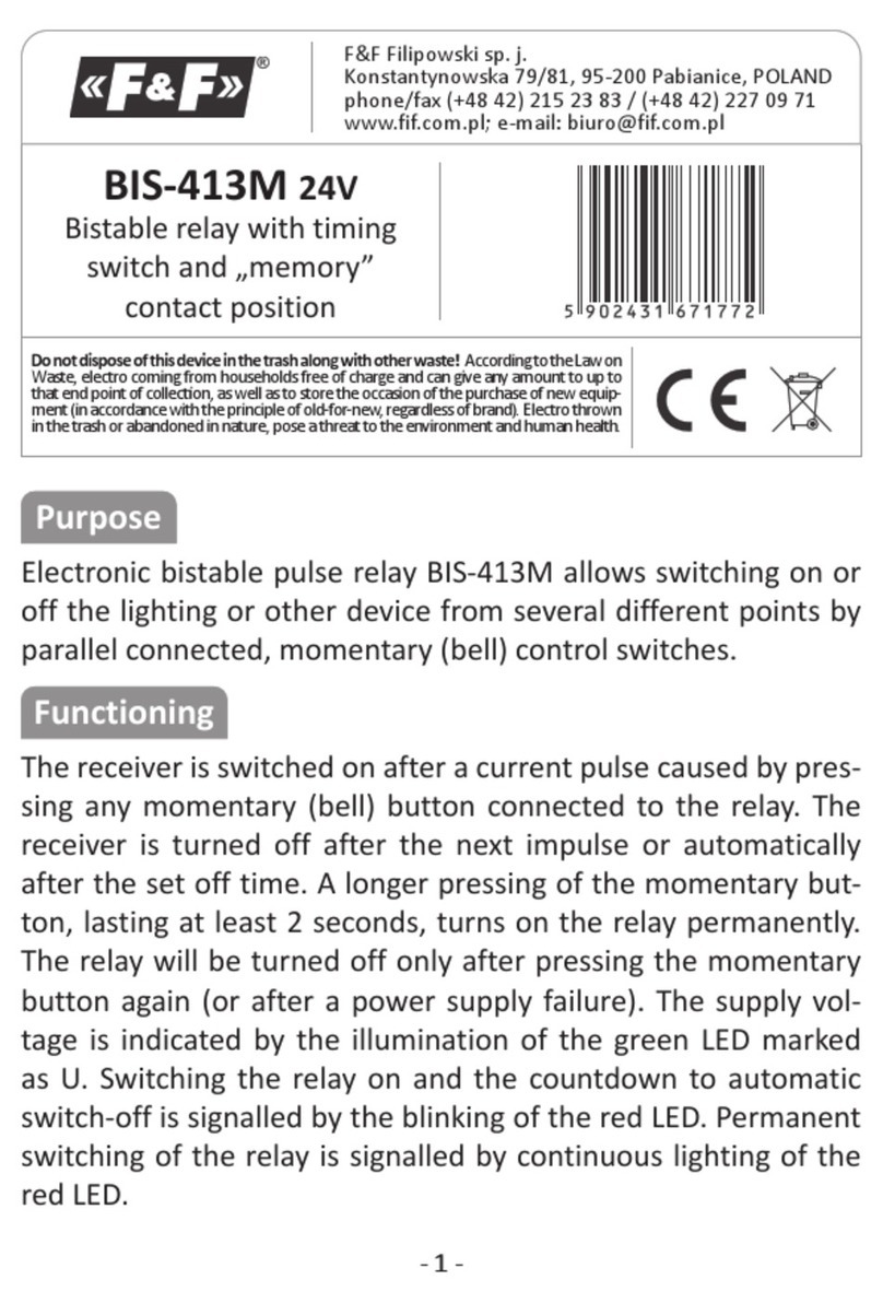
BIS-411i
24V
WARRANTY. The F&F products are
covered by a warranty of the 24 months
from the date of purchase. Effective only
with proof of purchase. Contact your
dealeror directly with us. More
information how to make a compliant can
be found on the website:
www.fif.com.pl/reklamacje
PURPOSE
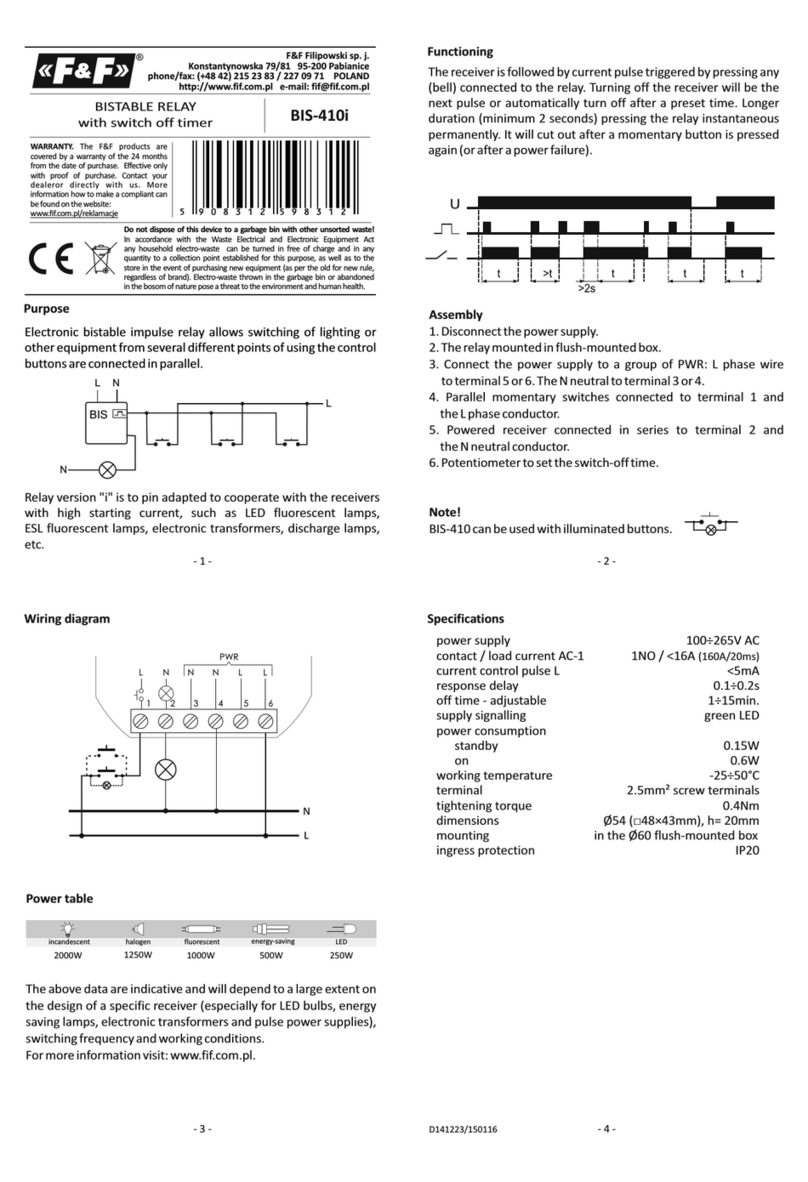
Electronic bi-stable pulse relays BIS-411i 24V enables the user to
actuate lighting or other devices from various locations by means
of control buttons in parallel connection.
- 1 - - 2 -
FUNCTIONING
The receiver is actuated by means of a current pulse triggered by
pushing any bell push connected to the relay. The receiver is
deactivated by another pulse or after a preset time. The relay does
not „memorize” the position of the relay contact, i.e. in case of
supply voltage decay and the subsequent return of supply voltage,
the relay contact will be set in the off position. Such a solution
prevents the automatic actuation of the receivers controlled that
might occur without proper supervision after a long-lasting decay
of supply voltage.
ATTENTION!
The BIS-411 24V not compatible with bell
pushes equipped with fluorescent lamps.
ASSEMBLY
1. Turn OFF the power.
2. Put on the relay on the rail in the switchgear box.
3. Connect the power cable to contact 1-3: for AC voltage any
polarity; for DC voltage: „+” connect to contact 3 and „-” to
contact 1.
4. The timers switching which are connect in parallel connect
to contact 6 and to cable which is connect to contact 3.
5. The activated receiver connect in series to contact 11-12.
- 4 -
D160121
Table of power
2000W 1000W
1250W
incandescent fluorescent
halogen energy-saving LED
500W 250W
Connection scheme (example)
different supply voltages of the relay and receiver
~/+
~/−
L
N
1
4
7
10
2
5
8
11
3
6
9
12
U
BIS-411
The above data are indicative and will heavily depend on the design of a
specific receiver (that is especially important for LED bulbs, energy-
saving lamps, electronic transformers and pulse power supply units),
switching frequency and operating conditions.
For more information visit www.fif.com.pl
TECHNICAL DATA
SUPPLY
1-3 power relay: 9÷30V AC/DC
CONTROL INPUTS
6 control input
CONTACT
11-12 output: NO contact (active)
power supply
contact / current load AC-1 separated 1 /
control pulse < mA
activation delay 0.1÷0.2sec
signalling of supply green LED
signalling of activation red LED
working temperature -25÷50°C
connection screw terminals
tightening torque 0.4 Nm
dimensions 1 module (18mm)
9 30
NO <16A (160A/20ms)
9÷30V AC 5
÷ V AC/DC
power consumption
standby 0.15W
on 0.6W
2
2.5mm
fixing on the TH-35 rail
ingress protection IP20
WIRING DIAGRAM
5 9 0 8 3 1 2 5 9 8 6 9 5
Relay version "i" is to pin adapted to cooperate with the receivers
with high starting current, such as LED fluorescent lamps,
ESL fluorescent lamps, electronic transformers, discharge
lamps, etc.
L
N
BIS
~/+ ~/−
~/+
- 3 -
13
6
~/+
~/−
11 12
