ZIEHL MS220KA User manual

ZIEHL industrie –elektronik GmbH + Co KG
Daimlerstr.13, 74523 Schwäbisch Hall, Germany
+ 49 791 504-0, info@ziehl.de, www.ziehl.de
Temperature Relays and MINIKA®
Mains Monitoring
Digital Panelmeters MINIPAN®
Switching Relays and Controls
Measuring Transducers
Grid- and Plant Protection
Operating Manual MS220KA and MSR220KA
updated: 2022-12-12 / nm
PTC thermistor relay with short-circuit detection
MS220KA and MSR220KA
10580-0701-06-GB
Seite 1 / 12
www.ziehl.de
0102
8507
Marking see type plate on the device
EU type examination certificate PTB 12 ATEX 3006 Issue 2
UK type examination certificate EPS 22 UKEX 1024

MS220KA and MSR220KA
10580-0701-06-GB
Seite 2 / 12
www.ziehl.de
Table of contents
1 General Notes......................................................................................................................................3
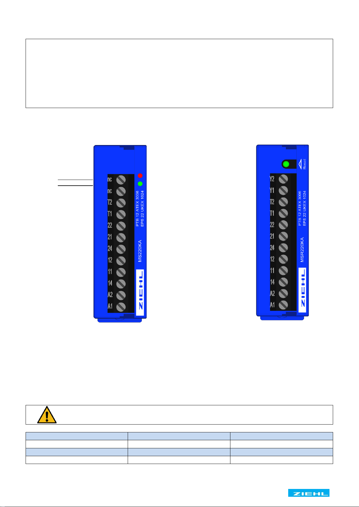
2 Display- and control elements............................................................................................................3
3 Pre-Adjustment....................................................................................................................................3
4 Application and brief description.......................................................................................................4
5 Summary of features...........................................................................................................................4
6 Connecting diagram............................................................................................................................4
7 Function diagram ................................................................................................................................5
8 Important notes ...................................................................................................................................5
9 Installation ...........................................................................................................................................5
10 Commissioning..................................................................................................................................6
11 Operating instructions......................................................................................................................6
12 Troubleshooting and remedies ........................................................................................................6
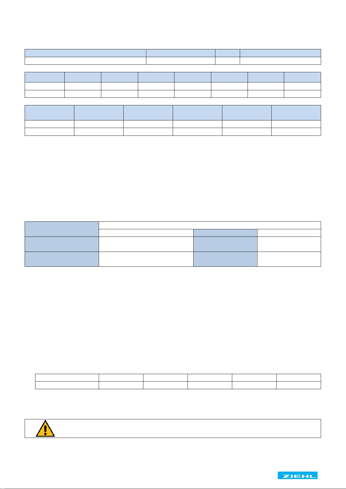
13 Technical data ...................................................................................................................................6
14 Dimensions - Design K......................................................................................................................8
15 Safety instructions and references for putting into operation.......................................................8
15.1 Explosive atmospheres..............................................................................................................8
15.2 Special remarks for explosive gas atmospheres areas (Zone 0, 1 and 2) ..................................8
15.3 Special remarks for use in the presence of combustible dust (Zone 20, 21, and 22)..................8
15.4 Safety characteristics of the safety device (EN 50495 / VDE 0170-18)......................................9
15.5 Category and Performance-Level (EN ISO 13849-1).................................................................9
15.6 Application of the safety device used with equipment category (EN 50495 / VDE 0170-18).......9
15.7 Wiring........................................................................................................................................9
15.8 Safe separation........................................................................................................................10
15.9 Stop function............................................................................................................................10
15.10 Start and restart.....................................................................................................................10
15.11 Manual reset..........................................................................................................................10
16 Proof testing of the safety functions..............................................................................................10
17 Maintenance and repair...................................................................................................................11
18 Disposal ...........................................................................................................................................11
19 EU / UK -Declaration of Conformity................................................................................................12

MS220KA and MSR220KA
10580-0701-06-GB
Seite 3 / 12
www.ziehl.de
1 General Notes
Compliance with the following instructions is mandatory to ensure the functionality and safety of the
product. If the following instructions given especially but not limited for general safety, transport, storage,
mounting, operating conditions, start-up, maintenance, repair, cleaning and disposal / recycling are not
observed, the product may not operate safely and may cause a hazard to the life and limb of users and
third parties.
Deviations from the following requirements may therefore lead both to the loss of the statutory material
defect liability rights and to the liability of the buyer for the product that has become unsafe due to the
deviation from the specifications
2 Display- and control elements
MS220KA
MSR220KA
Alarm (red)
ON (green)
Reset button
Alarm (red)
ON (green)
3 Pre-Adjustment
No settings have to be made. The tripping temperature is determined solely by the response temperature
of the connected thermistors.
Depending on the number of thermistors the following tripping temperatures and reset temperatures arise
related to TNF (detector operating temperature):
Attention!
Only 3 or 6 thermistors in series are allowed for usage in explosive atmospheres.
Tripping temperature
Reset temperature
1 PTC thermistor
TNF + 15 K
TNF + 5 K
3 PTC thermistors in series
TNF + 5 K
TNF –5 K
6 PTC thermistors in series
TNF
TNF –20 K

MS220KA and MSR220KA
10580-0701-06-GB
Seite 4 / 12
www.ziehl.de
4 Application and brief description
The device protects electrical equipment against excessive warming and thermal overload. Used in com-
bination with respective thermistors tripping temperatures from 60 °C up to 180 °C can be realized.
The device is conform to EN 60947-8. Thermistors according to DIN VDE V 0898-1-401 (ATEX) or
equivalent detail specification (UKEX) shall be connected. The thermistors are suitable for installation
into windings of electrical machines or transformers, bearings and heatsinks as well as to monitor the
temperature of liquid media, airflow and gases. With ATEX approval, equipment in explosive gas atmos-
pheres Zone 1 and 2 (marking G: gas) or in areas with combustible dust Zone 21 and 22 (marking D:
dust) can be protected. All functions of the device serve to protect non-explosive-protected equipment
and explosive-protected equipment in regular operation and in case of failure.
5 Summary of features
•1 thermistor circuit for 1 (not allowed for explosive atmospheres) 3 or 6 PTC thermistors.
•Short-circuit detection within the thermistor circuit.
•Output relay with 1 or 2 change-over contact (co).
•Operating status display.
A current monitors continuously the resistance of the thermistor circuit. In cold state, the resistance is ≤
250 Ω per thermistor (thermistor circuit ≤1.5 kΩ). The device is switched on and relay contacts 11, 14 and
21, 24 are closed. The resistance of the thermistor rises rapidly at detector operating temperature TNF.
The device switches off at a resistance of 3…4 kΩ and the relay contacts 11, 14 and 21, 24 close. The
device also switches off in the case of detector or line short-circuit (< approx. 20Ω) or detector or line
interruption. Device type MS switches on automatically when the temperature has cooled down. Device
type MSR remains switched off until the build in or an external reset button is pushed. Power-on is recog-
nized as reset. With bridged terminals Y1, Y2, the reclosing lock function is disabled and a device type
MSR works like a device type MS.
6 Connecting diagram
PTC
PTC thermistor
Us
Supply voltage
S1
Off switch
S2
Push button on
S3
Remote reset
H1
Indicator lamp fault
F1 –F4
Fuses
K1
Contactor
*1
External interlock
See chapter 15.11
Manual resetting
*2
Only MSR devices
*3
Only with 2 co

MS220KA and MSR220KA
10580-0701-06-GB
Seite 5 / 12
www.ziehl.de
7 Function diagram
MS220KA (automatic reset)
MSR220KA (reclosing lock)
1) Detector or line short-circuit
2) Caution! The relay switches on automatically after a supply voltage dip.
With a bridge at the reset input (Y1/Y2) the reclosing lock is out of operation. The
device switches back automatically, when the temperature of the thermistor circuit
has fallen below the switchback value.
8 Important notes
Attention!
Observe safety rules and standards. Notice safety remarks!
Attention!
Hazardous voltage!
May cause electric shock and burns.
Before commencing work on the system, the power must be disconnected.
9 Installation
•The applicant must observe safety rules and standards.
•The device can be mounted on 35 mm rail according EN 60715 or with screws M4 (Option)
•K –Design; vertical terminal block, width 22.7 mm
•The device must be installed in an enclosure of international protection class IP 5X or better.
•Terminals maximum tightening torque 0.5 Nm.
When installing the device into the switchgear cabinet, please observe the max. permissible
temperature. Care for both, sufficient clearance to other devices or sources of heat or enough
forced draught. If cooling is made more difficult, e.g. close devices with increased surface tem-
perature or by handicap of airflow cooling, the permissible ambient temperature reduces.

MS220KA and MSR220KA
10580-0701-06-GB
Seite 6 / 12
www.ziehl.de
10 Commissioning
Attention!
Before switching on the mains voltage make sure that it matches the specification
on the type plate.
Attention!
Observe chapter 15.8 Safe separation.
•After the supply voltage is switched on and when the thermistors are correctly connected the green
LED „ON“ must light-up and the relay contacts 11, 14 and 21, 24 must close.
•The correct function of the device must be checked by resistance simulation at terminals T1, T2 ac-
cording to chapter 16 Proof testing of the safety functions. This check must be repeated after changes
to the installation.
11 Operating instructions
The device type MSR must be manually reset after a fault signal (red = alarm). For this purpose, the
built-in illuminated reset button or an external button (remote reset terminals Y1, Y2) can be used.
12 Troubleshooting and remedies
Relay contacts 11, 14 or 21, 24 do not close:
•Check the supply voltage Us at terminals A1, A2 (green LED lights-up).
•Check the thermistors at terminals T1, T2. In case of a fault the red LED lights-up.
•The resistance of the thermistor circuit must be 50 Ω < R < 1500 Ω. The terminal voltage T1, T2 must
be < 2.5 VDC with connected thermistors and temperature below TNF.
•For device type MSR push the button “Reset”. A fault signal can be reset at R < 1.65 kΩ. The status
LED changes from red to green. Alternatively, a reset can be done with closing an external contact at
terminals Y1, Y2 or with voltage recovery.
Relay contacts 11, 14 or 21, 24 do not open:
•With no connection at terminals T1, T2 the device must indicate a fault and the relay contacts 11, 14
and 21, 24 must open. The terminal voltage T1, T2 must be approximately 8 VDC.
In case of any othermalfunctions, replace the device. Please add a description of the occurredmalfunction
when sending back for repair.
13 Technical data
Power supply (A1, A2)
Power supply Us
AC 110-120 V, AC 220-240 V, AC 380-415 V
(see type plate)
AC / DC 24 V (without galvanic isolation)
Voltage tolerance
AC 0.9 Us …1.1 Us
DC 21 ... 30 V
Frequency
50 / 60 Hz
Frequency tolerance
45 Hz … 65 Hz
Power consumption
< 2 W
Voltage dip buffer time
max. 20 ms
PTC thermistor input (T1, T2)
according to DIN VDE V 0898-1-401 or equivalent
Number
1 (not allowed for explosive atmospheres) 3 or 6 in series
Rated response temperature TFS
60 °C … 180 °C
Response tolerance
±6 °C
Collective resistance cold thermistor
≤ 1.65 kΩ
Terminal voltage (PTC thermistor)
≤ 2.5 VDC at R ≤ 3.65 kΩ, ≤ 2 VDC at R ≤ 1.65 kΩ
Open-circuit voltage
≤ 9 VDC at R =

MS220KA and MSR220KA
10580-0701-06-GB
Seite 7 / 12
www.ziehl.de
Terminal current (PTC thermistor)
≤ 1 mA
Power consumption
≤ 2 mW
Line capacity max.
0.2 µF
Temperature monitor cut-out-point
3.3 kΩ …3.65 kΩ …3.85 kΩ
Temperature monitor reclosing point
1.7 kΩ …1.8 kΩ …1.95 kΩ
Short circuit monitor cut-out-point
≤ 20 Ω
Short circuit monitor reclosing point
≤ 40 Ω
Reset input (Y1, Y2)
Potential free contact (no)
Current
1 mA
Voltage
< 30 VDC
Relay output (11,12,14 –21,22,24)
EN 60947-5-1
Contacts
1 or 2 change-over contacts (co)
Switching voltage
max. AC 400 V
Switch-on current (NO)
AC 15 A 4s 10% ED
min. voltage / current
12 V 10 mA
Conventional thermal current Ith
max. 5 A
Switching power max. AC cos φ = 1
2000 VA
Switching power max. DC (ohm)
0.25 A 300 V; 0.35 A 150 V; 1 A 60 V; 8 A 30 V
Contact life electrical cos φ = 1
2 x 10⁵operating cycles at 250 V / 2 A
1 x 10⁵operating cycles at 250 V / 5 A
Contact life mechanical
3 x 10⁷operating cycles
Recommended fuse (NO)
4 A time-lag or miniature circuit-breaker MCB B4
Recommended fuse (NC)
3,15 A time-lag
Utilization category
Rated operational current
Rated operational voltage
AC-15 Ie = 3 A Ue = 250 V
DC-13 Ie = 2 A Ue = 24 V
DC-13 Ie = 0.4 A Ue = 120 V
DC-13 Ie = 0.2 A Ue = 250 V
UL electrical ratings
250 VAC, 3 A, general use
C300
Test conditions
IEC/EN 60947-8
Rated impulse voltage
4000 V
Overvoltage category
III
Pollution degree
2
Rated insulation voltage Ui
320V
Transformer
EN 61558-2-6 (VDE 0570)
Proof Test Voltage
2500 VAC 50 Hz
EMC - Immunity
EN 61000-6-2
EMC - Emission
n.a., fmainosc < 9kHz
On-period
100 %
Ambient conditions
Fitting position
any
Rated ambient temperature
-20 °C ... +55 °C
Rated storage Temperature
-20 °C …+70 °C (1K21 EN 60721-3-1)
Altitude
≤ 2000 m above sea level.
Climatic conditions
5-85 % rel. F., no condensation (3K22 EN60721-3-3)
Vibration DIN EN 60068-2-6
2…25 Hz ±1.6 mm 25 ... 150 Hz 5 g
Vibration DIN EN 60947-8
2 … 13.2 Hz ± 1 mm 13.2 ... 100 Hz ± 0.7 g
Shock DIN EN 60947-8
half sine, 10 g, 11 ms
Housing
Design K
Dimensions (W x H x D) mm
22.5 x 75 x 115 mm
Width
1 M
Plastic material
PA66
Fire protection class
UL 94 V-2
Protection class housing EN 60529
IP 30
Mounting EN 60715
Snap mounting on 35 mm standard rail EN60715
Optional: Screw mounting
M4 screws (additional bar not included)
Weight
approx. 150 g
Terminal connection
Screw mounting M3

MS220KA and MSR220KA
10580-0701-06-GB
Seite 8 / 12
www.ziehl.de
Protection class terminals EN 60529
IP 20
Line connection solid wire
1 x 0.34 mm2–2.5 mm2 / AWG 22 - 14
Stranded wire
1 x 0.34 mm2–2.5 mm2 / AWG 22 - 14
Stranded wire with insulated ferrules
1 x 0.14 mm2–1.5 mm2 / AWG 28 - 16
Insulation strip length min
8 mm
Tightening torque
0.5 Nm
Subject to technical modifications
14 Dimensions - Design K
Dimensions in mm
1 Bottom piece
2 Top piece
3 Mounting bar
4 Screw
5 Holes for screw mounting
15 Safety instructions and references for putting into operation
Attention!
Safety Instructions and references
please read carefully!
15.1 Explosive atmospheres
•The increased danger within explosive atmospheres (gas or dust) requires the careful attention of the
safety instructions and references for putting into operation. Observe the national safety rules and
regulations for prevention of accidents as well as the standard EN 60079-14 / VDE 0165-1. All work
for the connection, for putting into operation and maintenance is to be implemented by qualified, re-
sponsible technical personnel. Inappropriate behaviour can cause heavy personal damage and dam-
ages to property.
•The response of device must directly switch off the motor, also when used together with inverters. This
must be implemented with circuitry.
15.2 Special remarks for explosive gas atmospheres areas (Zone 0, 1 and 2)
•The device must be installed outside potentially explosive gas atmospheres unless the device is pro-
tected by a suitable ignition protection type (for example a flameproof enclosure).
15.3 Special remarks for use in the presence of combustible dust (Zone 20, 21, and 22)
•The device must be installed outside potentially explosive dust atmospheres unless the device is pro-
tected by a suitable enclosure for dust atmospheres.

MS220KA and MSR220KA
10580-0701-06-GB
Seite 9 / 12
www.ziehl.de
15.4 Safety characteristics of the safety device (EN 50495 / VDE 0170-18)
Safety Integrity Level (EN 61508) and safety related parameters
Operating mode
Hardware architecture
HFT
Safety Integrity Level
low demand mode
1oo1
0
SIL 1
Type
MTBF
PFH
SFF
SD
SU
DD
DU
MS220KA
54 years
4.07E-07
55%
4.44E-07
5.55E-08
0
4.07E-07
MSR220KA
52 years
4.26E-07
55 %
4.52E-07
6.10E-08
0
4.26E-07
Type
Proof test inter-
val T1
1year
3 years
5 years
10 years
MS220KA
PFDavg
1.78E-03
5.35E-03
8.91E-03
1.78E-02
MSR220KA
PFDavg
1.87E-03
5.60E-03
9.33E-03
1.87E-02
Observe proof test interval according EN 60079-17 for electrical equipment ≤ 3 years.
15.5 Category and Performance-Level (EN ISO 13849-1)
The device fulfils the requirements of category 1 and PL = c. MTTFd= 100 years.
The data of the functional safety stated above are valid for an ambient temperature of 40 °C. Data for
additional ambient temperatures can be obtained on request.
15.6 Application of the safety device used with equipment category (EN 50495 / VDE 0170-18)
This standard describes the minimum requirements of safety integrity level and fault tolerance of a safety
device in the application together with the category of the Equipment Under Control (EUC).
EUC
Safety device
no safety device
SIL 1
SIL 2
Category 2
(2G, 2D) EPL = Gb, Db
Zone 1, Zone 21
Zone 0, Zone 20
Zone 0, Zone 20
Category 3
(3G, 3D) EPL = Gc, Dc
Zone 2, Zone 22
Zone 1, Zone 21
Zone 0, Zone 20
The device thus is suitable as safety device for Equipment Under Control (EUC) with HFT = 0 category 3
in Zone 1 and Zone 21. The combined equipment shall comply with the relevant standards EN 60079-0
according to the categories to match.
15.7 Wiring
•The lines of the thermistor circuit must be routed as separate control lines. Using lines of the supply
cable or other mains voltage lines is not permissible. If extreme inductive or capacitive stray effects
are to be expected by parallel cables of the power installation, shielded control lines should be used.
•The terminals Y1, Y2 may be attached parallel to a common resetting mechanism. Thermistor lines
must not be connected.
•The line resistance within the thermistor circuit may not exceed a value of 20 Ω to ensure short circuit
detection.
•Maximum of permissible length for thermistor circuit lines:
Wire length
2 x 1000 m
2 x 800 m
2 x 500 m
2 x 300 m
2 x 250 m
Wire cross section
2.5 mm2
1.5 mm2
1.0 mm2
0.75 mm2
0.5 mm2
•With commissioning and after modification of the plant the thermistor resistance must be checked with
a suitable measuring instrument. With a resistance < 50 Ω the sensor circuit is to be examined for
short-circuit.
Attention!
Check PTC’s only with measuring voltages of < 2.5 V.

MS220KA and MSR220KA
10580-0701-06-GB
Seite 10 / 12
www.ziehl.de
15.8 Safe separation
•Line circuits (A1, A2), (11, 12, 14) and(21, 22, 24)have a safe separation tolow-voltage electric circuits
(T1, T2) and (Y1, Y2).
•Devices with a combined supply voltage DC/AC 24 V have no galvanic isolation andmust be used with
a power supply according to EN 61558-2-6 (safety isolating transformer or battery grid) and with pro-
tected wiring.
15.9 Stop function
•A stop function triggered by the device must transfer the machine as fast as possible into a safe state.
The stop function must have top priority.
•In case of failure the device switches off the contactor / circuit breaker and prevents an overheating of
the isolation system and / or the surface temperature. The protective function of the device is only
guaranteed if wiring is done directly into the control circuit of the motor in accordance with the connec-
tion diagram. The contacts must be protected, to prevent welding.
15.10 Start and restart
•Only if no dangerous condition is present, a reset is allowed. Device type MS or device type MSR with
bridged terminals Y1, Y2 (auto reset) switches back on afterthe thermistorscooled down. This function
must not be used in applications where an automatic reset could cause personal injuries or damage to
property.
15.11 Manual reset
•When the device triggers a stop instruction, it must be maintained until the manual reset mechanism
is operated and safe conditions for a renewed start are given. The manual resetting may be only pos-
sible if all safety functions and protection devices are effective.
•Device type MSR have an electronic reclosing lock The stop instruction remains, until a reset is made
by pressing the push-button „Reset“. A start-up is only possible, if no case of failure occurs and the
motor is cooled down to a sufficient value of temperature.
•The device switches on automatically with return of supply voltage. The user must guarantee by exter-
nal interlock (see connection diagram) that the supervised machine does not start again independently.
Attention!
Safety circuits according to EN 60204 / EN 62061. The devices must not be used
alone for functions, where an automatic restart must be prevented.
16 Proof testing of the safety functions
•The safety function must be tested at regular intervals. It is recommended to carry out the proof-test
once a year. Depending on the zone risk, tests should be conducted more frequently. A fault is recog-
nized by the safety test. A fault between safety tests could cause loss of protection.
The following must be tested additionally to recurring examinations with maintenance services:
•The safety function must be tested by interrupt the thermistor circuit wire at terminals T1, T2.
•The short circuit monitoring function must be tested by bridging the thermistor circuit wires at terminals
T1, T2.
•The safety function must be tested by changing the resistance from 50 - 1500 Ohm to 4000 Ohm at
terminals T1, T2.
•For the device type MSR the function of the electronic interlock must be tested additionally.
•If an error is detected no restart must be induced until the error is cleared.

MS220KA and MSR220KA
10580-0701-06-GB
Seite 11 / 12
www.ziehl.de
17 Maintenance and repair
•The device is maintenance free. Only the manufacturer may perform repairs. We recommend testing
within the regular maintenance intervals of the plant, where the device is used. EN 60079-17 is to be
observed.
•The guarantee presupposes the observance of these operating instructions (safety and start-up in-
structions).
18 Disposal
Disposal should be carried out properly and in an environmentally friendly manner
in accordance with legal provisions.
ZIEHL is registered with the EAR Foundation under WEEE no.: DE 49 698 543
You will find this and other user manuals written in English under
www.ziehl.com
Sie finden diese und auch weitere Bedienungsanleitungen im Internet unter
www.ziehl.de
ZIEHL industrie –elektronik GmbH + Co KG
Daimlerstr. 13
74523 Schwaebisch Hall
Germany
Fon + 49 791 504-0 info@ziehl.de www.ziehl.de
ZIEHL-ABEGG UK Ltd.
Springfield Business Park
Chelmsford, Essex, CM2 5AS
United Kingdom
Fon + 44 1245 449010 info@ziehl-abegg.co.uk www.ziehl-abegg.com/en-gb

MS220KA and MSR220KA
10580-0701-06-GB
Seite 12 / 12
www.ziehl.de
19 EU / UKCA -Declaration of Conformity
EU / UKCA-Konformitätserklärung
EU / UKCA-Declaration of Conformity
Hersteller:
Manufacturer:
ZIEHL industrie-elektronik GmbH + Co KG
Anschrift:
Address:
Daimlerstr. 13
74523 Schwäbisch Hall
Germany
Produktbezeichnung:
Product description:
Kaltleiter-Relais
PTC Thermistor Relay
Typ:
Type:
MS220KA
T222445
T222451
T222455
MSR220KA
T222471
T222473
T222475
T222476
Wir erklären in alleiniger Verantwortung, dass oben
bezeichnetes Produkt den grundlegenden Anforderun-
gen entspricht, die in den folgenden Europäischen
Richtlinien und in den UK Rechtsverordnungen fest-
gelegt sind.
We declare under our sole responsibility that the above
designated product meets the basic requirements and
complies with the following directives of the European
Union and the UK Statutory Instruments:
2014/30/EU
SI/2016/1091
EMV Richtlinie
EMC Directive
2014/34/EU
SI/2016/1107
ATEX Richtlinie
ATEX Directive
2014/35/EU
SI/2016/1101
Niederspannungsrichtlinie
Low Voltage Directive
2011/65/EU
2015/863/EU
SI/2012/3032
RoHS Richtlinie
RoHS Directive
Angewandte harmonisierte / designierte Normen und
technischen Spezifikationen:
Applied harmonised / designated standards and tech-
nical specifications:
EN 50495:2010
EN 60947-8:2003 + A1:2006 + A2:2012
EN IEC 61000-6-2:2019
EN 61000-6-3:2007 + A1:2011 + AC:2012
EN IEC 63000:2018
Benannte Stelle und Nummer der EU-
Baumusterprüfbescheinigung:
Notified Body and number of the EU-type-examination
certificate:
PTB Physikalisch Technische Bundesanstalt 0102
PTB 12 ATEX 3006 A2
Zugelassene Stelle und Nummer der UK-
Baumusterprüfbescheinigung:
Approved Body and number of the UK-type-
examination certificate
Bureau Veritas Consumer Products Services United
Kingdom Limited, approved body No. 8507
EPS 22 UKEX 1024
CE-Kennzeichnung / UKCA-Kennzeichnung in:
CE marking / UKCA marking since:
2012 / 2022
Ort, Datum der Ausstellung:
Place, date of issue
Schwäbisch Hall, 25.10.2022
ppa.
Herbert Wahl
Verkaufsleitung
Sales manager
Other manuals for MS220KA
1
This manual suits for next models
1
Table of contents
Other ZIEHL Relay manuals

ZIEHL
ZIEHL TR 800 Web User manual

ZIEHL
ZIEHL MS220KA User manual

ZIEHL
ZIEHL STW1000V2 User manual

ZIEHL
ZIEHL SW32V User manual

ZIEHL
ZIEHL SPI1021 User manual

ZIEHL
ZIEHL UFR1001E User manual

ZIEHL
ZIEHL EFR4001IP User manual

ZIEHL
ZIEHL TR250 User manual

ZIEHL
ZIEHL TR 800 Web User manual

ZIEHL
ZIEHL MS220C User manual