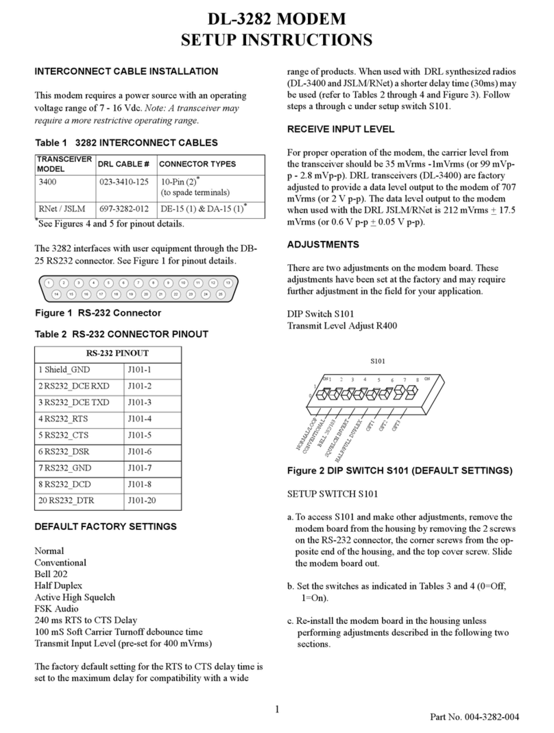
Dataradio DL-3282 User manual

S e r v i c e M a n u a l
DL-3282
1200BaudModem
PartNumber: 250-3282-002

DL-3282
1200 Baud Modem
Revision 001
001-3282-101/102 May 1999
Supersedes 001-3282-003 March 1999
Copyright” 1999 by Dataradio COR Ltd.
Dataradio COR Ltd. designs and manufactures radios and radio modems to serve a wide variety of data
communication needs. Dataradio produces equipment for the fixed data market including SCADA
systems for utilities, petrochemical, waste and fresh water management markets and RF boards for OEM
applications in the Radio Frequency Data Capture market.
PRODUCT WARRANTY
The manufacturer's warranty statement for this product is available from Dataradio COR, Ltd. 299
Johnson Avenue, Box 1733, Waseca, MN 56093-0833. Phone (507) 833-8819.
The information in this document is subject to change without notice.
is a trademark of DATARADIO,Inc.

i
Part No. 001-3282-101/102
TABLE OF CONTENTS
1GENERAL INFORMATION
1.1 INTRODUCTION . . . . . . . . . . . . . . . . . . . . . . . . . . . . . . . . . . . . . . . . . . . . . . . . . . . . . . . . . . . . . . . . . . . . . . . . . 1-1
1.2 MODEM DESCRIPTION. . . . . . . . . . . . . . . . . . . . . . . . . . . . . . . . . . . . . . . . . . . . . . . . . . . . . . . . . . . . . . . . . . . 1-1
1.3 FACTORY TECHNICAL SERVICE . . . . . . . . . . . . . . . . . . . . . . . . . . . . . . . . . . . . . . . . . . . . . . . . . . . . . . . . . 1-1
1.4 PRODUCT WARRANTY . . . . . . . . . . . . . . . . . . . . . . . . . . . . . . . . . . . . . . . . . . . . . . . . . . . . . . . . . . . . . . . . . . . 1-2
1.5 REPLACEMENT PARTS. . . . . . . . . . . . . . . . . . . . . . . . . . . . . . . . . . . . . . . . . . . . . . . . . . . . . . . . . . . . . . . . . . . 1-2
1.6 FACTORY REPAIR . . . . . . . . . . . . . . . . . . . . . . . . . . . . . . . . . . . . . . . . . . . . . . . . . . . . . . . . . . . . . . . . . . . . . . . 1-2
DL-3282 1200 BAUD MODEM SPECIFICATIONS . . . . . . . . . . . . . . . . . . . . . . . . . . . . . . . . . . . . . . . . . . . . . . . 1-3
2MODEM ADJUSTMENTS AND SETUP
2.1 INTERCONNECT CABLE INSTALLATION. . . . . . . . . . . . . . . . . . . . . . . . . . . . . . . . . . . . . . . . . . . . . . . . . . 2-1
INTRODUCTION . . . . . . . . . . . . . . . . . . . . . . . . . . . . . . . . . . . . . . . . . . . . . . . . . . . . . . . . . . . . . . . . . . . . . . . . . . 2-1
USER INTERFACE. . . . . . . . . . . . . . . . . . . . . . . . . . . . . . . . . . . . . . . . . . . . . . . . . . . . . . . . . . . . . . . . . . . . . . . . . 2-2
3282 LEDS . . . . . . . . . . . . . . . . . . . . . . . . . . . . . . . . . . . . . . . . . . . . . . . . . . . . . . . . . . . . . . . .. . . . . . . . . . . . . . . . 2-3
2.2 FACTORY DEFAULT SETTINGS . . . . . . . . . . . . . . . . . . . . . . . . . . . . . . . . . . . . . . . . . . . . . . . . . . . . . . . . . . . 2-3
INTRODUCTION . . . . . . . . . . . . . . . . . . . . . . . . . . . . . . . . . . . . . . . . . . . . . . . . . . . . . . . . . . . . . . . . . . . . . . . . . . 2-3
RECEIVE INPUT LEVEL . . . . . . . . . . . . . . . . . . . . . . . . . . . . . . . . . . . . . . . . . . . . . . . . . . . . . . . . . . . . . . . . . . . 2-3
2.3 ADJUSTMENTS . . . . . . . . . . . . . . . . . . . . . . . . . . . . . . . . . . . . . . . . . . . . . . . . . . . . . . . . . . . . . . . . . . . . . . . . . . 2-3
INTRODUCTION . . . . . . . . . . . . . . . . . . . . . . . . . . . . . . . . . . . . . . . . . . . . . . . . . . . . . . . . . . . . . . . . . . . . . . . . . . 2-3
DIP SWITCH S101 . . . . . . . . . . . . . . . . . . . . . . . . . . . . . . . . . . . . . . . . . . . . . . . . . . . . . . . . . . . . . . . . . . . . . . . . . 2-6
TRANSMIT OUTPUT LEVEL ADJUSTMENT . . . . . . . . . . . . . . . . . . . . . . . . . . . . . . . . . . . . . . . . . . . . . . . . . . 2-6
3THEORY OF OPERATION
3.1 INTRODUCTION . . . . . . . . . . . . . . . . . . . . . . . . . . . . . . . . . . . . . . . . . . . . . . . . . . . . . . . . . . . . . . . . . . . . . . . . . 3-1
3.2 FULL-DUPLEX/HALF DUPLEX OPERATION. . . . . . . . . . . . . . . . . . . . . . . . . . . . . . . . . . . . . . . . . . . . . . . . 3-2
3.3 DATA TONE BANDWIDTH . . . . . . . . . . . . . . . . . . . . . . . . . . . . . . . . . . . . . . . . . . . . . . . . . . . . . . . . . . . . . . . . 3-3
INTRODUCTION . . . . . . . . . . . . . . . . . . . . . . . . . . . . . . . . . . . . . . . . . . . . . . . . . . . . . . . . . . . . . . . . . . . . . . . . . . 3-3
PHONE LINE AND RF LINK BANDWIDTH. . . . . . . . . . . . . . . . . . . . . . . . . . . . . . . . . . . . . . . . . . . . . . . . . . . . 3-3
3.4 GENERAL AND LOOPBACK MODES. . . . . . . . . . . . . . . . . . . . . . . . . . . . . . . . . . . . . . . . . . . . . . . . . . . . . . . 3-3
GENERAL MODES . . . . . . . . . . . . . . . . . . . . . . . . . . . . . . . . . . . . . . . . . . . . . . . . . . . . . . . . . . . . . . . . . . . . . . . . 3-3
LOOPBACK MODES . . . . . . . . . . . . . . . . . . . . . . . . . . . . . . . . . . . . . . . . . . . . . . . . . . . . . . . . . . . . . . . . . . . . . . . 3-4
3.5 TRANSMITTING DATA . . . . . . . . . . . . . . . . . . . . . . . . . . . . . . . . . . . . . . . . . . . . . . . . . . . . . . . . . . . . . . . . . . . 3-4
INTRODUCTION . . . . . . . . . . . . . . . . . . . . . . . . . . . . . . . . . . . . . . . . . . . . . . . . . . . . . . . . . . . . . . . . . . . . . . . . . . 3-4
DTR SIGNAL . . . . . . . . . . . . . . . . . . . . . . . . . . . . . . . . . . . . . . . . . . . . . . . . . . . . . . . . . . . . . . . . . . . . . . . . . . . . . 3-4
RTS SIGNAL . . . . . . . . . . . . . . . . . . . . . . . . . . . . . . . . . . . . . . . . . . . . . . . . . . . . . . . . . . . . . . . . . . . . . . . . . . . . . . 3-4
DELAY PERIOD . . . . . . . . . . . . . . . . . . . . . . . . . . . . . . . . . . . . . . . . . . . . . . . . . . . . . . . . . . . . . . . . . . . . . . . . . . . 3-5
DATA FORMAT . . . . . . . . . . . . . . . . . . . . . . . . . . . . . . . . . . . . . . . . . . . . . . . . . . . . . . . . . . . . . . . . . . . . . . . . . . . 3-5
COMPLETING DATA TRANSMISSION . . . . . . . . . . . . . . . . . . . . . . . . . . . . . . . . . . . . . . . . . . . . . . . . . . . . . . . 3-5
3.6 RECEIVING DATA. . . . . . . . . . . . . . . . . . . . . . . . . . . . . . . . . . . . . . . . . . . . . . . . . . . . . . . . . . . . . . . . . . . . . . . . 3-6
INTRODUCTION . . . . . . . . . . . . . . . . . . . . . . . . . . . . . . . . . . . . . . . . . . . . . . . . . . . . . . . . . . . . . . . . . . . . . . . . . . 3-6
DTR SIGNAL . . . . . . . . . . . . . . . . . . . . . . . . . . . . . . . . . . . . . . . . . . . . . . . . . . . . . . . . . . . . . . . . . . . . . . . . . . . . . 3-6
CARRIER DETECT (CD) SIGNAL . . . . . . . . . . . . . . . . . . . . . . . . . . . . . . . . . . . . . . . . . . . . . . . . . . . . . . . . . . . . 3-6
COMPLETING DATA RECEPTION . . . . . . . . . . . . . . . . . . . . . . . . . . . . . . . . . . . . . . . . . . . . . . . . . . . . . . . . . . . 3-7
TABLE OF CONTENTS
ii
Part No. 001-3282-101/102
4PARTS LIST
5COMPONENT LAYOUT
6SCHEMATIC
LIST OF TABLES
2-1 3282 INTERCONNECT CABLES . . . . . . . . . . . . . . . . . . . . . . . . . . . . . . . . . . . . . . . . . . . . . . . . . . . . . . . . . . . . . .2-1
2-2 SWITCH S101 SETTINGS FOR BELL103/202. . . . . . . . . . . . . . . . . . . . . . . . . . . . . . . . . . . . . . . . . . . . . . . . . . . .2-4
2-3 DIP SWITCH S101 SETTINGS . . . . . . . . . . . . . . . . . . . . . . . . . . . . . . . . . . . . . . . . . . . . . . . . . . . . . . . . . . . . . . . .2-4
2-4 SWITCH S101 NORMAL CONVENTIONAL MODE OPTION SETTINGS . . . . . . . . . . . . . . . . . . . . . . . . . . . .2-5
2-5 SWITCH S101 TEST MODE SETTINGS . . . . . . . . . . . . . . . . . . . . . . . . . . . . . . . . . . . . . . . . . . . . . . . . . . . . . . . .2-5
3-1 MODEM TIMING PARAMETERS (BELL) . . . . . . . . . . . . . . . . . . . . . . . . . . . . . . . . . . . . . . . . . . . . . . . . . . . . . .3-6
LIST OF FIGURES
2-1 DL-3400 EXTERNAL CONNECTOR . . . . . . . . . . . . . . . . . . . . . . . . . . . . . . . . . . . . . . . . . . . . . . . . . . . . . . . . . . .2-1
2-2 RNet/ JSLM EXTERNAL CONNECTORS . . . . . . . . . . . . . . . . . . . . . . . . . . . . . . . . . . . . . . . . . . . . . . . . . . . . .2-2
2-3 RS-232 CONNECTOR PINOUT. . . . . . . . . . . . . . . . . . . . . . . . . . . . . . . . . . . . . . . . . . . . . . . . . . . . . . . . . . . . . . . .2-2
2-4 DIP SWITCH S101 . . . . . . . . . . . . . . . . . . . . . . . . . . . . . . . . . . . . . . . . . . . . . . . . . . . . . . . . . . . . . . . . . . . . . . . . . .2-6
2-5 MODEM BOARD ADUSTMENT POINTS. . . . . . . . . . . . . . . . . . . . . . . . . . . . . . . . . . . . . . . . . . . . . . . . . . . . . . .2-7
3-1 MODEM BOARD BLOCK DIAGRAM. . . . . . . . . . . . . . . . . . . . . . . . . . . . . . . . . . . . . . . . . . . . . . . . . . . . . . . . . .3-1
3-2 MODEM TONE FREQUENCY BANDS . . . . . . . . . . . . . . . . . . . . . . . . . . . . . . . . . . . . . . . . . . . . . . . . . . . . . . . . .3-2
3-3 MODEM INTERCONNECT DIAGRAM. . . . . . . . . . . . . . . . . . . . . . . . . . . . . . . . . . . . . . . . . . . . . . . . . . . . . . . . .3-7
5-1 3282 MODEM COMPONENT LAYOUT . . . . . . . . . . . . . . . . . . . . . . . . . . . . . . . . . . . . . . . . . . . . . . . . . . . . . . . .5-1
6-1 3282 MODEM SCHEMATIC . . . . . . . . . . . . . . . . . . . . . . . . . . . . . . . . . . . . . . . . . . . . . . . . . . . . . . . . . . . . . . . . . .6-1

SECTION 1
1-1
001-3282-101/102
GENERAL INFORMATION
1.1 INTRODUCTION
This manual contains setup and service information for the RS-232 Dataradio COR Ltd. Modem. This
modem can be purchased separately or as part of a telemetry module as described in the next section. Since the
telemetry module service manuals do not include modem servicing information, this service manual is used in all
applications.
1.2 MODEM DESCRIPTION
This modem can be purchased separately using Part No. 250-3282-002, or as part of a DRL DL-3400 or
DRL JSLM/RNetTelemetry Module using Part No. 023-3282-002.
The function of a modem is to convert digital data into an analog signal that can be used to modulate an
RF carrier. It also converts these analog signals back into digital data. This allows digital data to be transmitted and
received using an RF link.
This modem is compatible with Bell 103/202 standards for modems. It has an RS-232 compatible port for
interfacing with data equipment. An RF transmitter, receiver, or transceiver is required with this modem unless it is
used with some other type of link such as a phone line. Refer to Section 3 for a complete description of modem
operation.
1.3 FACTORY TECHNICAL SERVICE
The Technical Service Department provides customer assistance on technical problems and serves as an
interface with factory repair facilities. They can be reached in the following ways:
Dataradio COR Ltd.
299 Johnson Avenue, P.O. Box 1733
Waseca, MN 56093-0833
Technical Service hours are: Monday to Friday 7:30 AM to 4:30 PM, Central Time
Phone: 1-800-992-7774
or 1-507-833-8819
Fax:1-507-833-6748

GENERAL INFORMATION
1-2
001-3282-101/102
1.4 PRODUCT WARRANTY
The warranty statement for the Integra-TR is available by contacting your sales representative or by
sending your request to Dataradio COR Ltd. (see Section 1.3 for address).
1.5 REPLACEMENT PARTS
This product is normally not field-serviceable, except by the replacement of complete units. Specialized
equipment and training is required to repair logic boards and radio modems.
1.6 FACTORY REPAIR
Dataradio products are designed for long life and failure-free operation. If a problem arises, factory
service is available. Contact the Technical Service Department before returning equipment. A service
representative may suggest a solution eliminating the need to return equipment.
A Return Material Authorization (RMA) is required when returning equipment to Dataradio for repair.
Contact the Technical Service Department at 800-992-7774, extension 6707 to request an RMA number. Be
prepared to give the equipment model and serial number, your account number (if known), and billing and
shipping addresses.
Include the RMA number, a complete description of the problem, and the name and phone number of a
contact person with the returned units. This information is important. The technician may have questions that need
to be answered to identify the problem and repair the equipment. The RMA number helps locate your equipment
in the repair lab if there is a need to contact Dataradio concerning the equipment. Units sent in for repair will be
returned to the customer re-tuned to the current Dataradio Test and Tune Procedure and will conform to all
specifications noted in this section
Customers are responsible for shipping charges (to Dataradio) for returned units in warranty. Units in
warranty are repaired free of charge unless there is evidence of abuse or damage beyond the terms of the warranty.
Dataradio covers return shipping costs for equipment repaired while under warranty.
Units out of warranty are subject to repair service charges. Customers are responsible for shipping charges
(to and from Dataradio) on units out of warranty. Return shipping instructions are the responsibility of the
customer.

GENERAL INFORMATION
1-3
001-3282-101/102
DL-3282 1200 BAUD MODEM SPECIFICATIONS
The following are general specifications intended for use in testing and servicing this modem. These
specifications are subject to change without notice.
FCC ID Part 15
Dimensions (LxWxH) 4.75” x 2.90” x 1.237” (12.07cm x 7.37cm x 3.14cm)
Operating Voltage 7 to 16 VDC
Current Drain Less than 50mA
Temperature Range -30°C to +60°C
Data Interface EIA RS-232C Standard: DB-25 subminiature connector, female
DRLTM Brand Radio Interface 10-pin 3M type 3325 connector
RTS/CTS 30/60/180/240 msec
Data Rates FSK: 1200, 300 BPS
Data Format Transparent to asynchronous data
Bit Error Performance Less than 1 x 10⁻⁶ at 18 dB SINAD with 3.3 kHz deviation and
25 kHz RF channel bandwidth
Transmit Keyline Driver logic low open-collection NPN transistor with emitter
grounded IC(max.) = 100 mA; VCE-ON (max.) = 0.3 V

SECTION 2
2-1
001-3282-101/102
MODEM SETUP
2.1 INTERCONNECT CABLE INSTALLATION
2.1.1 INTRODUCTION
The modem requires a power source with an operating voltage range of 7 - 16 Vdc. NOTE: Transceiver
may require a more restricted operating range. Interconnect cables are available from DRL. Contact your sales
representative for details. Table 2-1 3282 INTERCONNECT CABLES
The external connector on the modem is a 3M-type male 10-pin ribbon connector. As shown in Figures 2-
1 and 2-2, only one power connection is required. Also shown in Figures 2-1 and 2-2 are the pin designations for
these connectors. Install these cables as required for your particular installation.
Figure 2-1 DL-3400 EXTERNAL CONNECTOR
TRANSCEIVER
MODEL DRL CABLE # CONNECTOR TYPES
DL-3400 023-3410-125 10-Pin (2)*(to spade terminals)
RNet/ JSLM 697-3282-012 DE-15 (1) & DA-15 (1)*
MODEM 10-PIN CONNECTOR ASSIGNMENTS
PIN FUNCTION
TYPICAL
COLOR
1
2
3
4
5
6
7
8
9
10
BROWN
BLUE
VIOLET
GREEN
RED
ORANGE
GRAY
YELLOW
BLACK
WHITE
Wideband Out
Wideband In
NOT USED
NOT USED
SUPPLY VOLTAGE (+)
TX KEY (PTT) OUT
CARRIER DETECT IN
TX NARROW BAND DATA OUT
GROUND (-)
RX NARROW BAND DATA IN
MODEM
TRANSCEIVER
1
2
9
10
10-Pin Connector Pinout
Note: Using Pins 1 & 2 to transmit data is not FCC approved. PART NO. 023-3410-125
(length: 3 ft.)

MODEM SETUP
2-2
001-3282-101/102
Figure 2-2 RNet/JSLM EXTERNAL CONNECTORS
2.1.2 USER INTERFACE
The 3282 interfaces with user equipment through the DB-25 RS232 connector. See Figure 2-3 for pinout
details.
RS-232 PINOUT & DESCRIPTION
1 Shield_GND J101-1
2 RS232_ DCE RXD J101-2
3 RS232_ DCE TXD J101-3
4 RS232_RTS J101-4
5 RS232_CTS J101-5
6 RS232_DSR J101-6
7 RS232_GND J101-7
8 RS232_DCD J101-8
20 RS232_DTR J101-20
Interconnect Cable (697-3282-012)
Length: 18 in
(connector end to connector end)
3 ft (power supply terminals
to JSLM connector end)
RNet/JSLM
Tx_Rx
Sub_Aud_Data
7 8 9 10 11 1265432 131
14 15 16 17 18 19 20 21 22 23 24 25
Figure 2-3 RS-232 CONNECTOR PINOUT

MODEM SETUP
2-3
001-3282-101/102
2.1.3 3282 LEDS
The 3282 has 2 LEDs (CR220) that are visible through the adjustment hole in the case closest to the 10 pin connector.
One LED will flash green whenever the modem has power and the microcontroller U220 is operating correctly. The
other red LED will be solid red whenever the modem is transmitting.
2.2 FACTORY DEFAULT SETTINGS
2.2.1 INTRODUCTION
Normal
Conventional
Bell 202
Half Duplex
Active High Squelch
FSK Audio
240 ms RTS to CTS Delay
100 mS Soft Carrier Turnoff debounce time
Transmit Input Level (pre-set for 400 mVrms)
The factory default setting for the RTS to CTS time is set to the maximum delay for compatibility with a
wide range of products. When used with DRL synthesized radios (DL-3400 and JSLM/RNet) a shorter delay
time (30 ms) may be used. These settings may require adjustment in the field to optimize performance in your
application.
2.2.2 RECEIVE INPUT LEVEL
For proper operation of the modem, the carrier level from the transceiver should be 35 mVrms -1 mVrms
(or 99 mVp-p - 2.8 mVp-p). DRL transceivers are factory adjusted to provide a data level output to the modem of
707 mVrms (or 2 V p-p) for use with the DRL DL-3400. The data level output to the modem when used with the
DRL JSLM/RNet is 212 mVrms +17.5 mVrms (or 0.6 V p-p +0.05 V p-p).
2.3 ADJUSTMENTS
2.3.1 INTRODUCTION
There are two adjustments on the modem board. These adjustments have been set at the factory and may require
further adjustment in the field for your application.
DIP Switch S101
Transmit Level R400

MODEM SETUP
2-4
001-3282-101/102
The following tables (2-2 through 2-4) show the various settings for Dip Switch S101 pictured in
Figure 2-4.
Table 2-2 SWITCH S101 SETTINGS FOR BELL 103/202
DIP Switch S101 Operating Mode Baud
Rate
Full/
Half
Dup Tx Freq Rx Freq
1 2 3 4 5 Space Mark Space Mark
(0=Off, 1=On) Normal Modes
0-1-1Bell 103 Answer 300 Full 2025 2225 1070 1270
0-1-0Bell 103 Originate 300 Full 1070 1270 2025 2225
0-0-1Bell 202 Full-Duplex 1200 Full 2200 1200 2200 1200
0-0-0Bell 202 Half-Duplex 1200 Half 2200 1200 2200 1200
12345 Loopback Modes
1-1-1Bell 103 Answer Loopback 300 Full 2025 2225 2025 2225
1-1-0Bell 103 Originate Loopback 300 Full 1070 1270 1070 1270
1-0-1Bell 202 Main Loopback 1200 Full 2200 1200 2200 1200
1-0-0Bell 202 Main Loopback 1200 Full 2200 1200 2200 1200
Table 2-3 DIP SWITCH S101 SETTINGS
DIP Switch S101
(0=Off, 1=On)
12345 Function
0* ----Normal Mode
1----Loopback Mode (Test Mode)
-0* ---Conventional Mode
- - 0* - - Bell 202 Mode (Half-duplex)
- - 1- - Bell 103 Mode
---0* -Active High Squelch Detect
---1-Active Low (Inverted) Squelch Detect
----0* Bell 103 Originate Mode/Bell 202 Half-Duplex Mode
----1Bell 103 Answer Mode/Bell 202 Full-Duplex Mode
* Factory Settings.

MODEM SETUP
2-5
001-3282-101/102
Table 2-4 SWITCH S101 NORMAL/CONVENTIONAL MODE OPTION SETTINGS
DIP Switch S101
(0=Off, 1=On)
12678 Function
0* 00* - - FSK Mode (Audio from and to the Modem IC is not routed through the filters on board).
This Mode is to be routed into an FSK/Audio Port of the Radio.
001- - WB Mode (Audio from and to the Modem IC is routed through the audio filters on board).
This Mode is to be routed into a Wide Band Port of the Radio.
0 0 -0 0 Time between activating PTT to activating Clear-To-Send (CTS) = 30 ms.
Time to debounce Soft Carrier Turnoff (SCT) at end of transmission = 25 ms.
0 0 -1 0 Time between activating PTT to activating Clear-To-Send (CTS) = 60 ms.
Time to debounce Soft Carrier Turnoff (SCT) at end of transmission = 50 ms.
0 0 -0 1 Time between activating PTT to activating Clear-To-Send (CTS) = 180 ms.
Time to debounce Soft Carrier Turnoff (SCT) at end of transmission = 75 ms.
0 0 -1* 1* Time between activating PTT to activating Clear-To-Send (CTS) = 240 ms.
Time to debounce Soft Carrier Turnoff (SCT) at end of transmission = 100 ms.
* Factory Setting
Table 2-5 SWITCH S101 TEST MODE SETTINGS
DIP Switch S101
(0=Off, 1=On)
12678 Function
1-0- - A Simulated Un-Asserted RTS Line from the RS-232C Connector (Un-Keys the transceiver).
1-1- - A Simulated Asserted RTS Line from the RS-232C Connector (Keys up the transceiver).
1- - 0 0 Transmit Data from the RS-232 Port.
1- - 0 1 Transmit Mark Tone.
1- - 1 0 Transmit Alternating Mark/Space Tones.
1- - 1 1 Transmit Space Tone.

MODEM SETUP
2-6
001-3282-101/102
Figure 2-4 DIP SWITCH S101
2.3.2 DIP SWITCH S101
DIP switch S101 has been factory set for the “Normal / Conventional / Bell 202 Half-Duplex / Active
High Squelch / 103 Originate Mode / FSK / CTS= 240 ms” mode. The factory default setting for the RTS to CTS
time is set to the maximum delay for compatibility with a wide range of products. When used with DRL
synthesized radios (DL-3400 and JSLM/RNet) a shorter delay time (30 ms) may be used. Refer to the tables
above and Figure 2-4 to change the delay times.
a.To access S101 and make other adjustments, remove the modem board from the housing by removing the
2 screws on the RS-232 connector, the corner screws from the opposite end of the housing, and the top cover
screw. Slide the modem board out.
b.Set the switches as indicated in the Tables above (0=Off, 1=On).
c.Re-install the modem board in the housing unless performing adjustments described in the following two
sections.
2.3.3 TRANSMIT OUTPUT LEVEL ADJUSTMENT
The transmit carrier level to the transceiver is factory preset for 400 mVrms. This is the input level
required by a DRL transceiver connected to the modem. If this level must be reset, proceed as follows:
a.If required, remove the modem board from the housing as described in Step a of Section 2.3.2.
b.Configure the telemetry equipment connected to the RS-232 jack to transmit a continuous data signal.
Alternatively, if no equipment is connected to this jack, configure S101 with switches 1 and 7 ON. Then
move switch 6 to ON to key-up the modem. The modem will transmit a continuous alternating space/mark
tone from U230.
S101
7 8
123456
ONON
NORMAL/LOOP
CONVENTIONAL
BELL202/103
SQUELCHINVERT
HALF/FULLDUPLEX
OPT1
OPT2
OPT3
0
1

MODEM SETUP
2-7
001-3282-101/102
c.Monitor the AC voltage at TP400, J102. Adjust R400 for 400 mVrms if using a DRL telemetry transceiver.
If another transceiver is used, adjust R400 as required. J103 pin 5 has a resistor that will drop the Tx output
level to 40 mVrms when connected to the DRL JSLM / RNet.
d.Re-install the modem board in the housing.
Figure 2-5 MODEM BOARD ADJUSTMENT AND TEST POINTS
Transmit Level Adjust
A Tuning tool should be used to perform adjustments on R400. This tool is available
from DRL’s Customer Service (see Section 1.3) as part number 721-0015-142S.

SECTION 3
3-1
001-3282-101/102
THEORY OF OPERATION
Figure 3-1 MODEM BOARD BLOCK DIAGRAM
3.1 INTRODUCTION
The function of the modem is to convert digital data into tones that can be transmitted using an RF link. It
also converts these tones back into digital data when the signal is received. A block diagram showing the modem,
the telemetry unit generating or receiving the data, and the RF receiver and transmitter is shown in Figure 3-1.
This modem can be used for full-duplex, half-duplex, or one-way data communications (refer to Section
3.2). The RF receiver/transmitter configuration determines which type of communication is possible. This modem
has an RS-232C compatible port for interfacing with the unit receiving or transmitting the data. A DIP switch on
the modem PC board programs the modem to operate according to one of the Bell standards listed in Table 2-2.
U240
J101
1SHIELD
2RS-232 RxD
RS-232 TxD 3
RS-232 RTS 4
RS-232 CTS 5
6RS-232 DSR
7RS-232 GND
8RS-232 DCD
20RS-232 DTR
22RS-232 RI
U230
U220
U200
TX AUDIO
RX AUDIO
1
2
3
4
5
6
7
8
1
2
3
4
5
6
7
8
J102 EXTERNAL
CONNECTOR
CONNECTOR
MOBILE RADIO
WB OUT
WB IN
FREQ SELECT
RSSI
+13.6V
PTT OUT
SQUELCH IN
TX DATA
9GROUND
10 RX DATA
J103
SQUELCH IN
PTT OUT
GROUND
WB OUT
TX DATA
INTERCEPT
TX MUTE OUT
+13.6V
9+13.6V
10
SUB AUDIO DATA
11 TX/RX
12 ARQ OUT
13 GROUND
14
WB IN
15 RX DATA
+13.6V
+13.6V
WB SEL
TX DATA
WB SEL
+5V
+13.6V
Q250/Q251
Q252
Q253
Q254
Q255
Q256
SCI BUS
CS BUS
ADDRESS BUS
U450D U401A U400B/C/D U401C
U450A
U450A U401B U450B/C
IRQ
+5V REGULATOR
RESET
+5V
NORM/LOOP
H/F DUPLEX
BELL 202/103
CONV
SQUELCH INV
OPT 1
OPT 3
OPT 2
S101

THEORY OF OPERATION
3-2
001-3282-101/102
Four integrated circuits on the modem PC board provide most of the modem functions. Microcontroller
U220 provides the control functions for Modem IC U230. Modem IC U230 provides filtering and analog/digital
conversion of the data. RS-232 interface IC U240 converts the -5V and +5V logic levels from the RS-232 port
(J101) to the 0V and +5V TTL levels required by U230 (it also inverts these levels). Regulator IC U200 produces
the +5V supply.
Figure 3-2 MODEM TONE FREQUENCY BANDS
3.2 FULL-DUPLEX/HALF DUPLEX OPERATION
Full-duplex means that data can be simultaneously transmitted and received. This type of operation allows
data to be transmitted and received at the same time in a remote site. Full-duplex operation requires a duplex
receiver and transmitter (transceiver) and two RF channels.
Half-duplex means that data can be both transmitted and received, but not at the same time. This type of
operation requires a simplex transceiver and only one RF channel.
If the modem is connected to only a receiver or transmitter instead of a transceiver, data transmission is
one-way. For example, if the modem is connected to only a transmitter, data can be transmitted from a site but not
received.

THEORY OF OPERATION
3-3
001-3282-101/102
3.3 DATA TONE BANDWIDTH
3.3.1 INTRODUCTION
The baud rate and modulating frequencies utilized by each of the programmable operating formats are
shown in Table 2-2. As indicated, 300 baud full- or half-duplex data rates are available with the Bell 103 mode and
1200 baud full- or half-duplex data rates are available with the Bell 202 mode. However these standards are
intended primarily for use with a two-wire phone line which provides simultaneous two-way communication.
Operation with an RF link is different because a single RF channel can provide communication in only one
direction at a time.
3.3.2 PHONE LINE AND RF LINK BANDWIDTH
The two tones used by this modem to transmit and receive data are in the audio range of approximately
300-3000 Hz. With a 2-wire phone line, full-duplex data transmission is achieved by frequency multiplexing two
300-baud channels into the 3000 Hz bandwidth of the phone line (refer to Figure 3-2). Each of these 300 baud
channels use two different frequencies. With half-duplex operation or pseudo full-duplex operation utilizing a back
channel (refer to next section), only one main data channel is transmitted at a time. The occupied bandwidth can be
greater and data can be transmitted at higher baud rates.
With an RF link, each RF channel also has a bandwidth of 3000 Hz. In half-duplex applications which use
a single RF channel, 300/1200 baud rates are available. For full-duplex operation, two RF channels are required
(similar to a 4-wire phone line). Since two 3000 Hz bandwidth channels are then available, full-duplex 1200 baud
data transmission is possible (versus 300 baud with a 2-wire phone line).
3.4 GENERAL AND LOOPBACK MODES
3.4.1 GENERAL MODES
When a General operating mode is selected, the receive and transmit filters in modem IC U230 are
configured for different frequencies. If the selected mode is a full-duplex mode, the transmit filter is set for the
transmit frequency and the receive filter is set for the receive frequency shown in Table 2-2. If the selected mode is
a half-duplex mode, the configuration of the receive and transmit filters is controlled by the RTS input of the RS-
232 port. If RTS is high (indicating data is to be transmitted), the transmit filter is set to the transmit frequency and
the receive filter is set to the back channel (refer to Section 3.5.3). If the RTS input is low, the receive filter is set to
the receive frequency and the transmit channel is set to the back channel.

THEORY OF OPERATION
3-4
001-3282-101/102
3.4.2 LOOPBACK MODES
When a Loopback mode is selected, both the filters in U230 are configured for the same frequency. Half-
duplex operation in the Loopback modes is the same as it would be in the General modes because the back channel
is not used.
If a full-duplex originate mode is selected, the filters are set to the transmit frequency; if a full-duplex
answer mode is selected, they are set to the receive frequency.
3.5 TRANSMITTING DATA
NOTE: The levels in the following information are the levels at the RS-232 port. The levels on the pins of U230 are
the inverse of these levels because of the inversion produced by U240.
3.5.1 INTRODUCTION
The transmit data signal originates from the data equipment. This data signal is applied to the TD
(Transmit Data) input of the RS-232 port, inverted and converted to TTL by U240, and then applied to the TxD
input of U230 and converted to the MARK and SPACE tones. These tones are fed out of U230 on the TxA
(Transmit Audio) pin. They are then routed to a separate RF transmitter module where they frequency modulate
the RF signal.
3.5.2 DTR SIGNAL
This signal indicates to the modem that the data equipment connected to the RS-232 port is ready to
transmit or receive data.
3.5.3 RTS SIGNAL
When the equipment connected to the RS-232 port is ready to send data, it brings the RTS (Request-To-
Send) input high. This signal must remain high for the duration of the data transmission. If the DTR input is low,
bringing the RTS input high has no effect. It is common protocol that a SPACE (logic 0 or low) be presented to the
Transmit Data (TxD) input just before the RTS input is made high. When the data transmission is finished, the
RTS input is brought back low which disables the transmitter section of U230. In the half-duplex General modes,
the RTS input also controls the transmit and receive filters in U230 as described in Section 3.4.1.

THEORY OF OPERATION
3-5
001-3282-101/102
3.5.4 DELAY PERIOD
When the RTS input of the RS-232 port goes high, a delay period tRC (On) is initiated (refer to Table 3-1).
During this delay period, a carrier is transmitted to alert the other modem that data is coming. After this delay
period expires, the Clear-To-Send (CTS) output of the RS-232 port goes high to indicate to the data equipment that
it may start sending data. Data is fed into the modem on the Transmit Data (TxD) pin of the port.
3.5.5 DATA FORMAT
NOTE: The data from the data equipment is inverted by U240. However, it is inverted again at the receiving end, so
the logic level at the RS-232 port is the same on both ends.
The data from the data equipment is converted to audio tones by U230 using FSK (Frequency-Shift-
Keying) modulation. A “Mark” tone is produced by a logic 0 (low) input to the RS-232 port, and a “Space” tone is
produced by a logic 1 (high) input. The frequency of these tones is shown in Table 2-1. When the TxD input
changes states, the tone frequency changes without any interruption in the signal (modulation is phase continuous).
The audio tones are synthesized by U230 using digital techniques.
Transmit filtering in U230 attenuates sideband energy present in the square-wave digital signal generated
by U230. This transforms into a sine wave. Transmit filtering also prevents interference with the back channel (not
used) or the other duplex channel.
3.5.6 COMPLETING DATA TRANSMISSION
When the data equipment is through sending data, it brings the RTS input of the RS-232 port back low
(Off). The TxD input is then disabled and a timing period tRC (Off) begins (refer to Table 3-1). With Bell 202
modes, soft turn-off and squelch occur during this timing period. Other modes do not utilize either function. At the
end of this period, the CTS output of the RS-232 port goes back low (Off).
The following is a brief description of soft turn-off and squelch:
Soft Turn-Off
When the RTS input of the RS-232 port goes low at the end of a message, transients may be generated
which could cause erroneous data to be received at the other modem. During soft turn-off, a 900 Hz Soft Carrier
Turn-off Tone is transmitted for a period tSTO after RTS goes low. This provides a steady “Turn Off” tone
followed by a silence at the other modem so that transients are not interpreted as data. The 900 Hz Soft Carrier
Turn-off is not available in Bell 103 mode.
Squelch
The squelch period tSQ is initiated when the RTS input of the RS-232 port goes low and if in Bell 202
mode the 900 Hz Soft Carrier Turn-off Tone is transmitted for tSTO (25 ms). During this period, the CD output is
clamped low (Off) which forces the RD output low. This disables the data receiver between the time RTS goes low
and the start of carrier detect so that transients are not demodulated.

THEORY OF OPERATION
3-6
001-3282-101/102
3.6 RECEIVING DATA
NOTE: The levels in the following information are the levels at the RS-232 port. The levels on the pins of U230 are
the inverse of these levels because of the inversion produced by U240.
3.6.1 INTRODUCTION
The receive data signal is FSK-modulated tones from an RF receiver module. This signal is applied to the
RxA (Receive Audio) input of modem IC U230. This device filters the tones to attenuate out-of-band frequencies
and then convert the tones to digital data. The data is then filtered again and fed out of U230 on the RxD pin. U240
inverts the data and converts it to RS-232 levels. It is then applied to the RxD pin of the RS-232 port.
3.6.2 DTR SIGNAL
The DTR signal indicates that the data equipment connected to the port is ready to receive or transmit
data.
3.6.3 CARRIER DETECT (CD) SIGNAL
When a tone is detected on the RxA input of U230 for a time tCD (On), the CD output of the RS-232 port
goes high. This tells the data equipment that data is coming. FSK-modulated tones on the RxA input are then
converted to digital data and fed out on the RxD output of the port.
Table 3-1 MODEM TIMING PARAMETERS (BELL)
Symbol Description Bell 103 Orig Bell 103
Answer Bell 202 Units
tRC (On) RTS to CTS on delay 30/60/180/240 30/60/180/240 30/60/180/240 ms
tRC (Off) RTS to CTS off delay 0.5 0.5 0.5 ms
tCD (On) Carrier Det on delay 8-20 8-20 6-12 ms
tCD (Off) Carrier Det off Delay 6-20 6-20 3-8 ms
tSQ Receiver squelch duration 60 60 33 ms
tSTO Transmitter soft turn-off duration - - 25 ms
Other manuals for DL-3282
1
Table of contents
Other Dataradio Modem manuals

Dataradio
Dataradio Gemini/PD+ User manual

Dataradio
Dataradio G3 User manual

Dataradio
Dataradio DL-3282 Manual

Dataradio
Dataradio GeminiG3 User manual

Dataradio
Dataradio Integra-TR User manual

Dataradio
Dataradio Gemini/PD+ User manual

Dataradio
Dataradio ViPR User manual

Dataradio
Dataradio G3 User manual

Dataradio
Dataradio Gemini PD User manual

Dataradio
Dataradio T-96SR User manual