Datavan DTV-07C User manual

Model: DTV-07C
Compact Line PC
User's Manual
M/B Ver. 2
July /15/1997.

2
CHAPTER 1 INTRODUCTIONS & KEY FEATURES
1.1 Introductions:
Congratulation on the purchase of your DTV-07C !
You are now the owner of a state-of-the-art DTV-07C - the one that offers features;
speed; and performance, and the one that is unrivaled and unattended by other conventional
Pentium-586-based PC.
1.2 Key Features:
Model number: DTV-07C
*** Options: ¡iDATA-POS DTV-074S 4S: 4 serial ports¡j
¡iDATA-MEDIA DTV-072S 2S: 2 serial ports
and with optional Internal CD ROM¡j
CPU: Supports full series of Intel PentiumTM CPU, Cyrix/IBM, AMD
CPU CLOCK - Intel PentiumTM 75Mhz up to 200Mhz. , Cyrix (IBM)
6x86 ..166+, AMD K5.....
CPU VOLTAGE - 5V, onboard voltage regulator: 2.5/ 3.3/ 3.45/ 3.56 V
MAIN MEMORY: 72 Pin SIMM x 2pcs (Fast Page mode or EDO mode)
BIOS combines video: Flash ROM - combines system BIOS with VIDEO BIOS in
a single Flash ROM , system BIOS complying with PLUG and PLAY
CACHE MEMORY: 256KB P.B.SRAM onboard, optional 0KB or 512KB
EXPANSION SLOTS: Support Free 3-Slots Bus Card consisting of :
ISA bus * 2, PCI / ISA bus * 1,
*** SERIAL PORT:
(4S: 4 Serial) Four Serial ports, freely selectable IRQ & base address
range. 2 ports x RS232, 1 port x RS232/422/485,1 port x
RS232/422
(2S: 2 Serial) Two Serial ports, freely selectable IRQ & base address
range. 2 ports x RS232
PARALLEL PORT: One Parallel port (SPP/ EPP/ ECP)
FDD: 1.44MB/ 3.5" FDD x 1
ENHANCE PCI IDE: For AT bus IDE
PCI XGA / SVGA/ VGA PORT - 32bit Cirrus Logic 7548 chip default 1MB, up to 2MB
(CRT, LCD): - Display output to connect either MONITOR or COLOR LCD
both can display simultaneously.
- Connectors: CRT 15pin DSub and LCD 44pin DSub.
- Integrated programmable frequency synthesizer, 24bit true-
color, RAMDAC, 64*64 pixel size hardware pop-up icons.
- LCDs: 640*480 (VGA), 800*600 (SVGA) and 1024*768
(XGA)
*** WATCHDOG: Driving triggered by software, Watchdog Timer defined
(Default spec for 4S) by jumper setting from 1/4 to 256 seconds.
KEYBOARD PORT: Standard AT DIN keyboard.
PS/2 MOUSE PORT: Yes
FRONT PANEL: LED indicators: POWER, TURBO, HDD. Door Cover
to protect floppy disk and power switch
POWER SUPPLY: 80W Internal Power Supply (UL, CSA, VDE, EMI meets
FCC *B*)
POWER SOURCE: AC 90V to 264V, 60HZ/50HZ

3
CASE DIMENSION: 11"(W)x11"(D)x3"(H) (280x280x75mm)
EXPORT PACKING: Each set packing: 13.5"x13.5"x6.75" (34x34x17cm)
Each set NW/GW: 5kgs/ 6kgs.
Two sets packing: 15.35"x15.35"x14.76" (39x39x37.5cm)
SAFETY: CE, FCC
S/W Compatibility: MS-DOS 4.01/5.0/6.2, OS2 V2.1, SCO XENIX: V2.3.2,
SCO UNIX V3.2, NOVELL, WINDOWS 3.1/ 95/ NT
OPERATION TEMPERATURE: 0 o Cto 55 oC
STORAGE TEMPERATURE: -25 o Cto 70oC
Dimension: Mainboard: 26.5cm(w) x15 cm(D); Screw Holes: 0.5cm.
System: 28cm x 28cm x 7.5cm(11" x 11"x 3").
Export Packing: Each set packing 34cm x 34cm x 17cm (13.5" x 13.5" x 6.75").
Two Sets packing 39cm x 39cm x 37.5cm(15.35" x 15.35" x 14.76").
OPTIONS:
1. COMBO CARD: Optional, built-in RAM DISK/ Cash drawer port * 2 for +5V or +12V.
2. INTERNAL CD ROM KIT: Optional Internal CD ROM Kit including:
1) 2-Slots Bus card (ISA bus *1, PCI/ISA bus * 1)
2) Internal CD ROM with Cable
3) Metal bracket + Front Panel for Internal CD ROM
4) Sound card
3. SUSPEND MODE: Optional for ODM
4. USB (Universal Serial Bus): Optional for ODM
5. PS/2 Keyboard port: Optional for ODM or Optionally supplies conversion adapter for DIN to
MINI DIN of PS/2 keyboard. (Modifying)
Note : All brand names and trademarks are the property of their respective owners.

4
CHAPTER 2 SYSTEM CONFIGURATION -
GETTING FAMILIAR WITH DTV-07C
2.1 The System Unit Chassis:
The following information will help acquaint you with the arrangement of the DTV-07C
computer.
When you open the box; what you will have will be same as Figure 2-1:
Figure 2-1 Export Packing
Figure 2-1 shows the full packing. In each set of packing, in both sides we might put : power
cord, mouse (option), and in the center is the system unit containing 3.5" floppy disk , hard
disk (option), internal CD ROM (option).
2.2 The Front Panel Composition:
Figure 2-2 Front View of System Unit

5
2.3 The Rear Panel Composition:
From left to right, the rear panel of DTV-07C contains the following:
Figure 2-3 Rear View of System Unit
2.4 The System Internal Composition:
Figure 2-4 The System Internal Composition

6
DTV-07C Mainboard Layout (4 * RS-232 Version)
41
JP
5
3
1
3
¡ ³¡ ´¡ ´
1
¡ ³¡ ³¡ ³
43
3
¡ ³¡ ´¡ ´
1
¡ ³¡ ³¡ ³
JP
42
6
4
2
JP
ON
¡ ¼¡ ¼¡ ¼¡ ¼
S1
¡ ¼¡ ¼¡ ¼¡ ¼
OFF
1
2
3
4
3
¡ ´
39
2
¡ ´
40
JP
1
¡ ³
JP
¡ ´¡ ´
¡ ³¡ ³
2
4
38
¡ ´¡ ´
58
¡ ³
36
12
¡ ³¡ ³¡ ³¡ ³¡ ³¡ ³¡ ³¡ ³
11
JP
¡ ´¡ ´
JP
¡ ³
JP
10
¡ ³¡ ³¡ ³¡ ³¡ ³¡ ³¡ ´¡ ´
9
1
3
8
¡ ³¡ ³¡ ³¡ ³¡ ³¡ ³¡ ³¡ ³
7
3
¡ ³
6
¡ ³¡ ³¡ ³¡ ³¡ ³¡ ³¡ ³¡ ³
5
28
¡ ´
35
4
¡ ³¡ ³¡ ³¡ ³¡ ´¡ ´¡ ³¡ ³
3
JP
1
¡ ´
JP
2
¡ ´¡ ´¡ ´¡ ´¡ ³¡ ³¡ ³¡ ³
1
¡ ³¡ ´¡ ´
23
24
25
26
3
¡ ³¡ ´¡ ´
1
JP
JP
JP
JP
27
JP
JP 55
JP 54
¡ ³¡ ³¡ ³¡ ³
21
3
1
3
¡ ³¡ ³¡ ³¡ ³
5
¡ ³¡ ³
JP
¡ ³¡ ³
22
2
¡ ´¡ ´¡ ³¡ ³
3
¡ ³
29
¡ ³¡ ³
JP
1
¡ ´¡ ´¡ ³¡ ³
1
¡ ³
JP
4
2
52
53
20
¡ ´
19
JP
JP
JP
¡ ´
JP
¡ ´¡ ´¡ ³¡ ´
3
¡ ´¡ ´¡ ³¡ ´
2
3
1
¡ ³
1
¡ ´¡ ³
17
14
13
15
16
¡ ´¡ ³
JP
JP
JP
JP
JP
4
2
U
P
3
¡ ³
C
2
¡ ´
12
1
¡ ´
JP
8
7
¡ ³¡ ³
3
8
7
¡ ³¡ ³
FA
¡ ³¡ ³ ¡ ³¡ ³
3
¡ ³
¡ ³¡ ³ ¡ ³¡ ³
60
2
¡ ´
51
¡ ´¡ ´
J1
¡ ´¡ ´
JP
1
¡ ´
JP
3
¡ ³
2
1
¡ ´¡ ´ ¡ ³
9
2
¡ ´
1
3
1
2
1
HDD
¡ ³
JP
1
¡ ´
JX
¡ ´¡ ³
2
2
4
6
8
¡ ³
8
3
¡ ´ ¡ ´¡ ³
JP
¡ ´¡ ³¡ ´¡ ´
59
TB
¡ ³
JP
2
¡ ´
1
4
2
¡ ´¡ ³¡ ´¡ ´
JP
¡ ³
4
1
¡ ³
JP
1
3
5
7
P/S
¡ ³
JP
26.5 cm x 15 cm
DTV- 07C Ver 2.0
Jumper Location
CPU: Intel Pentium 166 MHz

7
DTV-07C Mainboard Layout (2 * RS-232 Version)
41
JP
3
¡ ³¡ ´¡ ´
1
3
¡ ³¡ ´¡ ´
1
42
JP
ON
¡ ¼¡ ¼¡ ¼¡ ¼
S1
¡ ¼¡ ¼¡ ¼¡ ¼
OFF
1
2
3
4
3
¡ ´
39
2
¡ ´
40
JP
1
¡ ³
JP
¡ ´¡ ´
¡ ³¡ ³
2
4
38
¡ ´¡ ´
58
¡ ³
36
12
¡ ³¡ ³¡ ³¡ ³
11
JP
¡ ´¡ ´
JP
¡ ³
JP
10
¡ ³¡ ³¡ ³¡ ³
9
1
3
8
¡ ³¡ ³¡ ³¡ ³
7
3
¡ ³
6
¡ ³¡ ³¡ ³¡ ³
5
¡ ´
35
4
¡ ³¡ ³¡ ³¡ ³
3
1
¡ ´
JP
2
¡ ´¡ ´¡ ´¡ ´
1
23
24
JP
JP
21
¡ ³¡ ³
JP
¡ ³
29
¡ ³
JP
¡ ´
19
¡ ´
JP
¡ ´¡ ´¡ ³¡ ´
3
¡ ´¡ ´¡ ³¡ ´
2
3
1
¡ ³
1
¡ ´¡ ³
17
14
13
15
16
¡ ´¡ ³
JP
JP
JP
JP
JP
4
2
U
P
3
¡ ³
C
2
¡ ´
12
1
¡ ´
JP
3
8
7
FA
¡ ³¡ ³ ¡ ³¡ ³
3
¡ ³
¡ ³¡ ³
60
2
¡ ´
51
¡ ´¡ ´
JP
1
¡ ´
JP
3
¡ ³ ¡ ´¡ ´ ¡ ³
9
2
¡ ´
1
2
1
HDD
¡ ³
JP
1
¡ ´
JX
2
4
6
8
¡ ³
8
3
¡ ´ ¡ ´¡ ³¡ ´¡ ´
59
TB
¡ ³
JP
2
¡ ´
1
¡ ´¡ ³¡ ´¡ ´
JP
¡ ³
4
1
¡ ³
JP
1
3
5
7
P/S
¡ ³
JP
26.5 cm x 15 cm
DTV- 07C Ver 2.0 - 2 * RS-232
Jumper Location
CPU: Intel Pentium 166 MHz

8
* Specification of DTV-07C PentiumTM 586 AIO Logic board
“***”remarks the difference between “Data-POS (DTV-07C4S)”and “Data-MEDIA
(DTV-07C 2S)”
CPU:
Supports full series of Intel PentiumTM CPU, Cyrix/IBM, AMD
CPU CLOCK -
Intel PentiumTM 75Mhz up to 200Mhz , Cyrix (IBM) 6x86
..166+
CPU VOLTAGE -
5V, onboard voltage regulator: 2.5V/ 3.3V/ 3.45V/ 3.56V
MAIN MEMORY:
72 Pin SIMM x 2pcs (Fast Page mode or EDO mode)
BIOS combines video
Flash ROM combines system BIOS with VIDEO BIOS in a
BIOS with SYSTEM BIOS
single Flash ROM , system BIOS complying with PLUG and
PLAY
CACHE MEMORY:
256KB P.B.SRAM onboard, optional 0KB or 512KB
EXPANSION BUS:
Support Free 3-Slots Bus Card consisting of :
ISA bus * 2 , PCI/ ISA bus * 1.
***SERIAL PORT: - 4 S version
4 COM ports, freely selectable IRQ & base address range
2 ports x RS232, 1 port x RS232/422/485,1 port x RS232/422
(Option) - 2 S version
2COM ports ; 2 ports x RS232
PRINTER PORT:
LPT1, 25pin Dsub connector, SPP/EPP/ECP
ENHANCE PCI IDE:
Supports devices - Primary for HDD, Secondary for CD ROM
FDD PORT:
Supports 2 devices
PCI XGA / SVGA/ VGA
- 32bit Cirrus Logic 7548 chip default 1MB, up to 2MB
PORT (CRT, LCD):
- Display output to connect either MONITOR or COLOR
LCD
- Connectors: CRT 15pin DSub and LCD 44pin DSub.
- Integrated programmable frequency synthesizer, 24bit true
color
RAMDAC, 64*64 pixel size hardware pop-up icons.
- LCDs: 640*480 (VGA), 800*600 (SVGA) and 1024*768
(XGA)
PS/2 MOUSE PORT:
Yes
KEYBOARD PORT:
Standard AT DIN keyboard.
***WATCHDOG:
Driving triggered by software, Watchdog Timer defined
by jumper setting from 1/4 to 256 seconds. (Default spec. for
4S version, Not for 2S version)
BUZZER:
Yes
BACKUP BATTERY:
DALLAS or DALLAS compatible
POWER INPUT:
+5V,-5V,+12V, -12V.
PCB SIZE:
265 x 150 mm
OPERATION / STORAGE TEMPERATURE:
0 o Cto 55 oC / -25 o C to 70 oC
EMI APPROVAL:
FCC CLASS B (CONSIDERATION FOR CE) test by
customers

9
* IRQ & I/O MAP of DTV-07C PentiumTM 586 AIO Logic board
Logic Board
IRQ
I/O map
Mem Map
Remark
(Factory
Default)
(Factory
Default)
(Factory
Default)
SYSTEM TIMER
0
040-05F
KEYBOARD
1
060-06F
PS/2 MOUSE PORT
12
COM 1
4
3F8
Hardware/Soft
ware
selectable IRQ
3,4,5,7,9,10,11.
COM 2
3
2F8
ditto
*** COM 3 (4S Ver.)
5
3E8
ditto
*** COM 4 (4S Ver.)
9
2E8
ditto
LPT
7
378
PCI IDE PRIMARY
14
1F0
PCI IDE SECONDARY
15
017
FLOPPY DISK
6
3F0
PCI VGA
C000-
C7FF
***WATCHDOG (4S Ver.)
NA
200-201
Jumper Select-
able , 280-281
300-301, 380-
381
PCI LAN CARD
11
300
Optional item
Remarks : System Board Chipset : ALI 1521/1523
Super I/O Chipset : ALI M5113 & 16C2550
PCI LCD/VGA chip : Cirrus Logic 7548
Watchdog Timer: DTV ODM
PCI LAN card: Optional Item.

10
2.5 The Connector & Jumper Pin Location:
Following pages are tables of DTV-07C Jumper Setting for:
CPU TYPE
CPU VOLTAGE REGULATOR OUTPUT
CACHE RAM SIZE
CMOS
SYSTEM BIOS FLASH ROM VOLTAGE
ENHANCED SUPER I/O
VGA
WATCHDOG
POWER MANAGEMENT FOR LCD PANEL
CPU COOLING FAN
Note: In following pages, the jumper setting with “*”mark means Factory default
value on regular shipments.

11
DTV-07C JUMPER SETTING
CPU TYPE
JP13
JP14
JP15
JP17
JX1
CORE/ B US R A TIO
CPU
(BUS) Freq.
CPU
CPU Model
Freq.
(BUS) Freq.
Voltage
RATIO
Type
1, 2 3, 4
Type
AMD-SSA/5-75ABR
75MHz
50MHz
3.52V
1.5x
Open
Open
Open
Short
Short
1, 2
AMD-K5-PR90ABQ
90MHz
60MHz
3.52V
1.5x
Open
Open
Open
Short
Open
1, 2
AMD-K5-PR100ABR
100MHz
50MHz
3.52V
2x
Open
Short
Open
Short
Short
1, 2
AMD-K5-PR133ABQ
133MHz
66MHz
3.52V
2x
Open
Short
Open
Open
Short
1, 2
AMD-K5-PR166ABR
166MHz
66MHz
3.52V
3x
Short
Short
Open
Open
Short
1, 2
IBM26 6x86-2V2100GB
100MHz
50MHz 3.3V 2x
Short
Short
Short
Short
Short
2, 3
6x86-P150+
120MHz
60MHz
3.52V
2x
Open
Short
Short
Short
Open
2, 3
6x86L-P150+ (1)
120MHz
60MHz 2.8/3.3 2x
Open
Short
Short
Short
Open
2, 3
6x86-P166+
133MHz
66MHz
3.52V
2x
Open
Short
Short
Open
Short
2, 3
Intel Pentium
100MHz
50MHz 3.3V 2x
Open
Short
Open
Short
Short
1, 2
Intel Pentium
120MHz
60MHz 3.3V 2x
Open
Short
Open
Short
Open
1, 2
Intel Pentium
133MHz
66MHz 3.3V 2x
Open
Short
Open
Open
Short
1, 2
Intel Pentium
166MHz
66MHz 3.3V
2.5x
Short
Short
Open
Open
Short
1, 2 *
Intel Pentium
200MHz
66MHz 3.3V 3x
Short
Open
Open
Open
Short
1, 2
(1) Dual Supply (split rail) devices
JP59 CPU VCORE Voltage Selector
VOUT
1 - 2
3 - 4
5 - 6
7 - 8
2.2V
OPEN
SHORT
OPEN
OPEN
2.6V
OPEN
SHORT
SHORT
OPEN
2.7V
SHORT
SHORT
SHORT
OPEN
2.8V
OPEN OPEN OPEN SHORT
2.9V
SHORT
OPEN OPEN SHORT
3.2V
OPEN OPEN
SHORT
SHORT
3.3V
SHORT
OPEN
SHORT
SHORT
* default
3.5V
SHORT
SHORT
SHORT
SHORT
JP60 CPU 3V Selector
1 - 2
3 - 4
5 - 6
7 - 8
Single Power
SHORT
SHORT
OPEN
OPEN
*default
Dual Power
OPEN OPEN SHORT
SHORT
CMOS Clear
Normal
* Clear CMOS If you forget password, you must clear CMOS RAM
JP21
Open
Short
and reconfigure the system.
SYSTEM BIOS Flash ROM Voltage Selector
CACHE RAM SIZE
FLASH ROM +12V
*
FLASH ROM + 5V
256 KB
512 KB
JP35
1, 2 2, 3 JP1
2, 3
* 1, 2

12
Enhanced Super I/O
M5113 Enhanced Super I/O Controller
M5113
Enabled *
Disabled
JP12
1, 2 2, 3
COM1, 2, 3, 4, IRQ Selector
IRQ3
IRQ4
IRQ5
IRQ7
IRQ9
IRQ10 IRQ11
COM1
JP23
1, 2 * 3, 4 5, 6 7, 8
9, 10
11, 12
COM2
JP24
1, 2 * 3, 4 5, 6 7, 8
9, 10
11, 12
COM3
JP25
1, 2 3, 4 * 5, 6 7, 8
9, 10
11, 12
COM4
JP26
1, 2 3, 4 5, 6 7, 8
9, 10
*
11, 12
COM3, COM4 Address Selector
COM3(3F8)
/
COM4(2F8)
COM3(3E8)
/
COM4(2E8)
*
JP29
Short
Open
COM1 ~ COM4 D-SUB9 Pin Normal OR Add +5V For CCD
Normal *
Add +5V for CCD
COM1
JP42
1, 2 2, 3
COM2
JP41
1, 2 2, 3
COM3
JP27
1, 2 2, 3
COM4
JP28
1, 2 2, 3
COM3,COM4 RS232 / RS422 / RS485 Type Selector
Serial Port
JP20
RS-232 RS-422
RS-485
Model 1
Model 2
COM3 1, 2
Open
*
Short
COM4 3, 4
Open
*
Short
Open
Short
Map to JP43 5, 6
Open
*
Open
Short
Short
COM4 Selector COM3 Selector
RS-232/
*
RS-422
RS-485
RS-485
Type Selector
JP43
RS-422
by Terminator
by Terminator
RS-232 *
RS-422
1, 2
Open
Open
Short
Short
JP52
1, 2 2, 3
3, 4
Open
Open
Short
Short
JP53
1, 2 2, 3
5, 6
Open
Short
Open
Short
COM3, COM4 Enabled or Disabled Selector
Serial Port
Enabled *
Disabled
COM3 Open Short
JP54
COM4 Open Short
JP55

13
VGA
On Board VGA Selector
Enabled
*
DISABLE
JP58
1,2
Short
3,4
Short
1,2
Open
3,4
Open
JP40
2,3
Short
1,2
Short
Use VGA Bank 1 (U43, U44 256K*16 DRAM)
Enabled
*
Disabled
JP36
Open
Short
VGA Selector use IRQ2/9
None use IRQ2/9
*
Use IRQ2/9
JP38
Open
Short
VGA Selector MCLK or XMCLK
MCLK
XMCLK
JP39
Short
*
Open
LCD Panel Screen Setting
Code for Panel
Panel Description
Panel Resoiution
S1
Supported
1
2
3
TFT
640*480
Of
f
Of
f
On
TFT
800*600
Of
f
Of
f
Of
f
DSTN
640*480
On
Of
f
On

14
DTV-07C RS422/485 Interface Connection Table
Onboard: JP47,48
2*5 Jumper Pin
RS422 Output
DB9-Sub Male
RS485 Output
DB9-Sub Male
GND
1
¡³
¡³
2
CTS+
1
GND
1
GND
2
RTS+
(N.U)
2
RTS+
(N.U)
RTS+
3
¡³
¡³
4
CTS-
3
RTS-
(N.U)
3
RTS-
(N.U)
4
TXD+
4
TXD+
S.C.
RTS-
5
¡³
¡³
6
RXD
+
5
TXD-
8
RXD+
6
CTS+
(N.U)
6
CTS+
(N.U)
TXD+
7
¡³
¡³
8
RXD-
7
CTS-
(N.U)
7
CTS-
(N.U)
8
RXD+
5
TXD-
S.C
TXD-
9
¡³
¡³
10
N.C
9
RXD-
9
RXD-
* S.C.: Short Circuit
** COM3 RS422:JP47, COM4 RS422: JP48 or COM4 RS485: JP48
DTV-07C RS232 Interface Connection Table
Onboard: J7,8, JP45,46
2*5 Jumper Pin
RS232/422/485 use
the same Cable
RS232 Output
DB9-Sub Male
2*5 IDC
D-SUB9P
Male
DCD
1
¡³
¡³
2
DSR
1
DCD
1
1
2
RXD
2
6
RXD
3
¡³
¡³
4
RTS
3
TXD
3
2
4
DTR
4
7
TXD
5
¡³
¡³
6
CTS
5
GND
5
3
6
DSR
6
8
DTR
7
¡³
¡³
8
RI
7
RTS
7
4
8
CTS
8
9
GND
9
¡³
¡³
10
N.C
9
RI
9
5
** COM1 RS232:JP7, COM2 RS232:JP8, COM3 RS232: JP45, COM4 RS232: JP46

15
CHAPTER 3 UPGRADING
Watch Dog
Watch Dog Selector
Watch Dog Timer Selector
Enabled
Disabled
* JP2 1, 2 3, 4 *
JP16
1, 2 2, 3 J1
Timer
Timer
1, 2 *
4 Seconds
60 Seconds
3, 4
8 Seconds
120 Seconds
5, 6
12 Seconds
180 Seconds
7, 8
16 Seconds
240 Seconds
For Manufactory Test
For factory Dispatch
Watch Dog I/O Port Address Selector
WDCLK Address
200H
*
280H
300H
380H
JP22
RIG Address
201H
281H
301H
381H
1, 2
Open
Open
Short
Short
3, 4
Open
Short
Open
Short
Power Management Selector For LCD Panel
Suspend Mode Standby Mode
Enabled
Disabled
Enabled
Disabled
JP33
Open
*
Short
Map to JP31
(Manufactory Setup)
JP34
Open
*
Short
Map to JP32
(Manufactory Setup)
CPU Cooling FAN(FA3) use +5V or +12V Selector
JP51
Voltage
1,2
+12V
*
2,3
+ 5V
JP3 Buzzer
J9
LCD Panel Connector (44 Pin Female)
JP4 POWER LED
JP50
PS/2 Mouse Connector (6 Pin Female)
JP8 Turbo LED
J8 COM1
JP9 HDD LED
J7 COM2
FAN, FA1
FAN Connector
JP45
COM3
KB1
Keyboard Connector (5 Pin Female)
JP46
COM4
J10
VIDEO Connector (15 Pin Female)
JP47
RS-422 FOR COM3
J2 Floppy Driver Connector
JP48
RS-422/RS-485 FOR COM4
J3
Primary IDE Connector

16
NOTE:
Your warranty remains in effect only if an authorized dealer or technician adjusts the
internal settings. This section is intended only for those users who wish to perform the
adjustments themselves and void the warranty.
At any time, you can add (or remove) hardware to your DTV-07C computer and modify
its capabilities. The information in this chapter will instruct you on how to open the chassis.
3.1 Removing The Cover:
WARNING : make sure that the power to your systems, as well as any peripheral
devices, is off before removing the chassis.
Remove 2 screws located at the both sides of the system. Use the pulling knob to pull
out the system tray from the chassis. The system tray contains the Main Board, hard disk,
floppy disk and add-on card (option)
When you remove the system from the chassis, You are suggested to mark or label
plugs for correct orientation for simplified reassemble. Improperly plugging connectors or
plugs can damage your system when you power it up.
Ready with a tray to hold screws, and label the tray so you know where the screws will
go for reassemble. Since your system required different sizes of screws, keeping screws
separated will save you time and minimize frustration.
3.1.1 Tools
You will need a few simple tools to remove the DTV-07C Compact Line PC Machine.
* Philips screwdriver
* Labeling material (tape, paper, pen) (optional)
* Cups or trays to hold various screws (optional)
3.1.2 Adding Add-On Card:
DTV-07C includes 3 slots card for additional peripheral.
WARNING : Because of DTV-07C space-saving design, it is restricted that the additional
Add-on card for DTV-07C is within the maximum dimension: 108 mm (height) *
250mm (length). Please make sure that the Add-on card you are going to plug in DTV-
07C systems is according to this requirement.
3.2 Installing The Hard Disk:
WARNING: If you buy a DTV-07 without hard disk and you like to upgrade it
later. Please consult with your dealer. The procedures are as following:
1. Apply 3.1 opening the DTV-07C case.
2. Pull pulling knob to remove the outside case.
3. Screw on the hard disk and connect power cable and data cable. Select right power cable
for different brand Hard Disk.
4. Test the system and format hard disk before screwing in the system CHASSIS. Make sure
the system is in good condition.
5. By opposite direction to screw on the systems.
3.3 Memory Configuration:

17
The DTV-07C lets you increase the system main memory via onboard SIMM (Single
in-Line Memory Modules) Sockets. The DTV-07C supports Two banks of
4/8/12/16/20/24/32...MB SIMM Modules. The DTV-07C requires SIMM:
3.3.1 Suggested to use EDO SIMM Memory Modules
3.3.2 For FP SIMM Memory Modules, it is suggested to use 60ns.
3.3.3 It is able to use FP or EDO only with the same type of Memory Modules at the
same time.
The DTV-07C support the following configuration:
Memory Size
BANK 0 (SIMM 1)
BANK 1 (SIMM 2)
4MB
1*4MB
N.C.
8MB
1*4MB
1*4MB
1*8MB
N.C.
12MB
1*8MB
1*4MB
16MB
1*8MB
1*8MB
1*16MB
N.C.
20MB
1*16MB
1*4MB
24MB
1*16MB
1*8MB
32MB
1*16MB
1*16MB
1*32MB
N.C.
64MB
1*32MB
1*32MB

18
CHAPTER 4 BIOS SETUP
4.1 Setup Overview:
The DTV-07C contains its own permanently programmed SETUP routing, which
allows it to recognize and utilize the system's hardware, for example, one can set the system
to identify hard disk and floppy disk drive capacity, the type of video being used, and the
amount of memory installed. The BIOS (BASIC input / output System) will read this
information each time the system boots up. In the first time the system is powered on, please
run SETUP to configure it properly.
4.2 AMI BIOS Setup:
The BIOS setup program provided with the Main Board is the AMI BIOS from
American Megatrends Inc.. Enter the AMI Setup program's Main Menu as following:
1. Turn on or reboot the system.
2. After a serial of diagnostic check; press the <DEL> key to enter the AMI
BIOS setup program and the following screen appears :
*3. Pls seletor the “Auto Configuration with Optimal Settings” First.
DTV-07C Compact Line System BIOS Setup Manual
4.2.1. SETUP:
A. Standard:

19

20
Table of contents
Popular Single Board Computer manuals by other brands

IEI Technology
IEI Technology NOVA-9152 Quick installation guide
GATEWORKS
GATEWORKS Venice GW720 operating manual
Corvalent
Corvalent Captor M Quick installation guide
Motorola
Motorola CompactPCI CPN5365 Installation and use guide
Masimo
Masimo SafetyNet Alert quick start guide
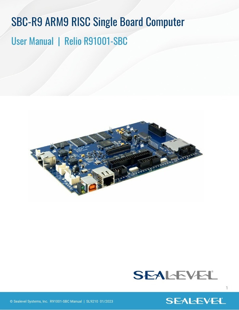
SeaLevel
SeaLevel SBC-R9 user manual

ADLINK Technology
ADLINK Technology NuPRO-841 user manual
PEP
PEP VM162 user manual
StarFive
StarFive VisionFive 2 quick start guide
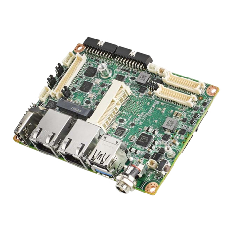
Advantech
Advantech RSB-3720 user manual
GigaDevice Semiconductor
GigaDevice Semiconductor GD32VW55 Series user manual

Lanner electronics
Lanner electronics EM-9560 Series user manual
