Datawell BV Hippy 40-MkII User manual

March 20, 2019
Datawell Heave Pitch Roll Sensor
Manual
Hippy 40-MkII
from serial no. 18181
Service & Sales
Voltastraat 3
1704 RP Heerhugowaard
The Netherlands
+31 72 534 5298
+31 72 572 6406
www.datawell.nl

2

3
Contents
1 Introduction ................................................................................................... 5
2 Principle of operation.................................................................................... 6
2.1 Acceleration measurement....................................................................... 6
2.2 High pass filter for heave measurement................................................... 6
2.3 Pitch-roll measurement ............................................................................ 7
3 Connections................................................................................................. 10
4 Position ........................................................................................................ 11
5 Outputs......................................................................................................... 12
5.1 Pitch (p).................................................................................................. 12
5.2 Roll (r) .................................................................................................... 12
5.3 Heave and acceleration ......................................................................... 12
6 Platform offset ............................................................................................. 13
6.1 Influence of platform offset..................................................................... 13
6.2 Amount of platform offset ....................................................................... 13
6.3 Platform orientation ................................................................................ 13
7 Transportation ............................................................................................. 14
8 Specifications .............................................................................................. 15
8.1 General .................................................................................................. 15
8.2 Pitch-roll ................................................................................................. 16
8.3 Heave..................................................................................................... 17
8.4 Acceleration ........................................................................................... 18
9 System check and calibration (heave) ...................................................... 19
9.1 Simple System check............................................................................. 19
9.2 Calibration .............................................................................................. 19
10 System check and calibration pitch and roll........................................... 20
11 Alignment................................................................................................... 22
12 Maintenance and repair ............................................................................ 24
12.1 Location of components (see fig. 6 and 8) ........................................... 24
12.2 Humidity ............................................................................................... 24
12.3 Repair and pcb check........................................................................... 26
12.3.1 Repair ........................................................................................... 26
12.3.2 Pcb check ..................................................................................... 27
12.4 Coils ..................................................................................................... 28
12.5 Accelerometer check............................................................................ 28
12.6 Exchange of pcb .................................................................................. 29
13 Check of fluid level.................................................................................... 31
14 Modifications ............................................................................................. 32
15 Dimensions and connections................................................................... 33
Appendix ........................................................................................................A-1
4
fig. 1

5
1 Introduction
The Hippy measures pitch, roll and heave.
Reference plane for the pitch-roll measurements is a gravity stabilised platform with a natural
period time of 40 seconds.
An accelerometer is mounted on this stabilised platform.
The sensor can accept any voltage between 10 and 30 V DC.
Output and supply are floating with regard to each other as well as to the housing of the sensor.

6
2 Principle of operation
Acceleration measurement2.1
The deflection of the tip of a clamped cantilever is a measure for the acceleration. (Vertical
acceleration since the accelerometer is mounted on a gravity stabilised platform).
The cantilever is placed in a fluid in which an electric field is present.
So the potential of the cantilever is a measure for this deflection.
No static friction is involved; the acceleration measurement is without hysteresis.
High pass filter for heave measurement2.2
The heave is obtained by double integrating the acceleration.
Temporary offset of the platform caused by horizontal acceleration (varying ship's speed) leads
to false acceleration outputs; in order to minimise the resulting false heave outputs a high pass
filter is used.
The remaining false output caused by a 180° reversal of ship's direction is proportional to the
square of the ship's speed, and amounts to approx.0.15 m at ship's speed of 1 m/sec.
The resulting transfer of high pass filter is:
ibaai 1.211 2
8.30Ta
170Tb
timeperiodT
Resulting amplitude transfer and phase shift is given under the specifications for some
frequencies.
7
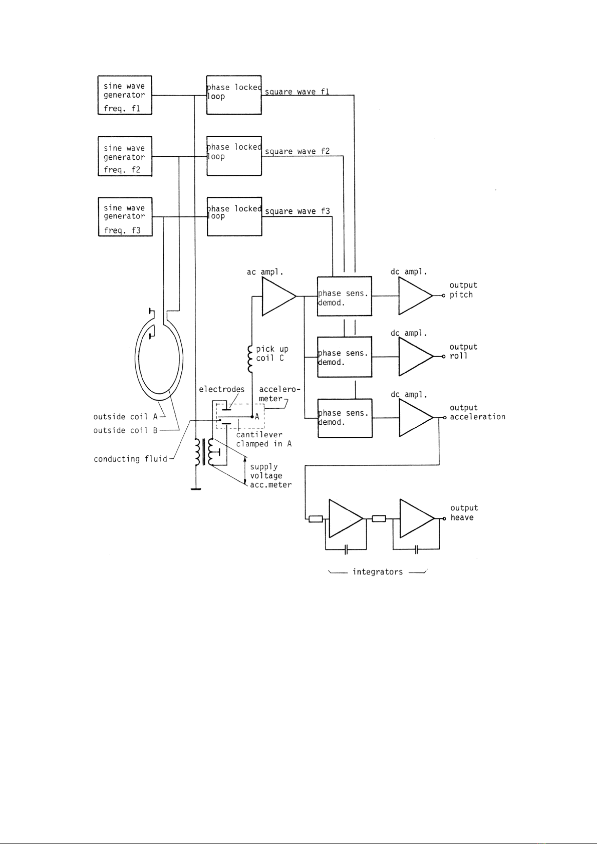
Pitch-roll measurement2.3
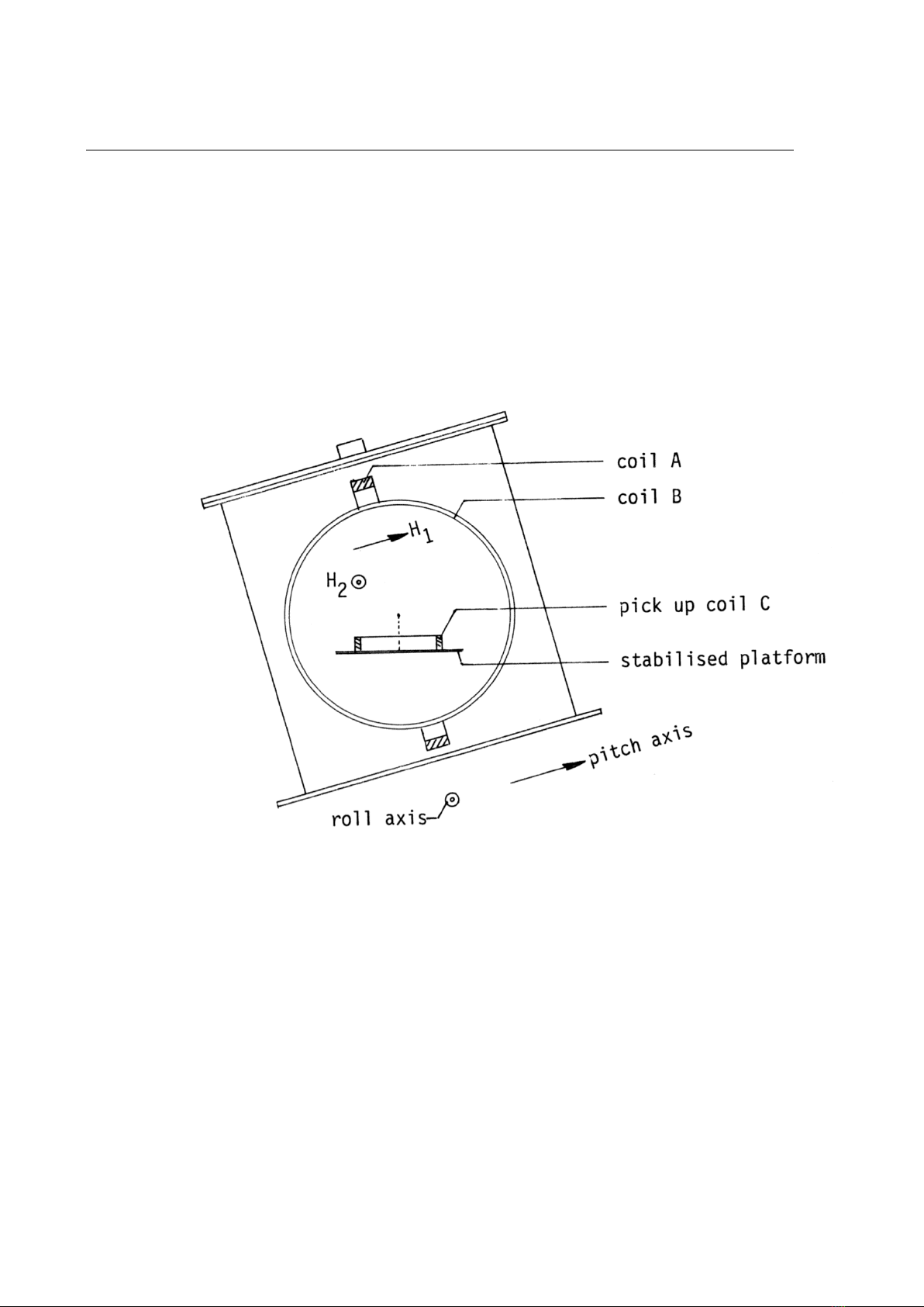
An alternating magnetic field H1is generated parallel to pitch axis and another field H2at
different frequency parallel to roll axis (by means of coils A and B, fixed to housing and
perpendicular to each other).
A pickup coil C, mounted on the stabilised platform (horizontal plane) measures the vertical
components of H1and H2(fig. 2 and 3).
The induced voltage in coil C is amplified, phase sensitive demodulated and amplified again.
The pickup coil is placed in series with the output of the accelerometer.
See block diagram fig. 1.
fig. 2

8
fig. 3
Calculation of induced voltage
Vi is base plane of instrument
Vh is horizontal plane (platform plane)
OL intersection of both planes
Angle between both planes is α
Be H1= P the magnetic field vector generated parallel to the pitch axis.
OP1the projection of OP on horizontal plane.
Component of H1perpendicular to Vh = PP1
So induced voltage in pickup coil on platform plane = ei;
ei= PP1/OP = sin ∠POP1(roll output)
also is PP1/OP = PP1/PL . PL/OP = sinαsinβ

9
So roll output r = sin∠POP1 = sinαsinβ
Also pitch output p = sin∠ROR1 = sinαcosβ
For scale factor see specifications (8.2).
α= angle between instrument plane and horizontal plane
β= angle between pitch axis and rotation axis
∠POP1=angle between pitch axis and horizontal plane
∠ROR1=angle between roll axis and horizontal plane

10
3 Connections
+junction box terminal no. 1
Supply
−junction box terminal no. 2
pitch junction box terminal no. 3
roll junction box terminal no. 4
Outputs heave junction box terminal no. 5
acceleration junction box terminal no. 6
common junction box terminal no. 7
For cable diameters see fig. 10.

11
4 Position
Pitch and roll axis are indicated by V formed cuttings in the rim of the bottom flange.
Mount the instrument with arrow (on text plate on lid) in the direction of the bow of the ship
(see fig. 10).
V formed cuttings in lid and top flange should coincide.

12
5 Outputs
Pitch (p)5.1
Measures sine of angle γ1between roll axis of ship and horizontal plane.
p (in volts) = 10 sin γ1
Output is positive if rear side of ship is lifted.
Roll (r)5.2
Measures sine of angle γ2between pitch axis of ship and horizontal plane.
r (in volts) = 10 sin γ2.
Output is positive if port side of ship is lifted.
The mast angle α(equal to angle between base plane and horizontal plane) can be derived from
both outputs according to
222
sin rp
(see fig. 3)
Angle
between pitch axis and horizontal rotation axis is equal to
prtgarc
(see fig. 3)
Heave and acceleration5.3
The Hippy delivers heave in the frequency range of 1/30 –1 Hz.
An output giving acceleration from DC –1 Hz is available.

13
6 Platform offset
Influence of platform offset6.1
Platform offset is directly shown by the pitch and roll outputs if the ship is accurately trimmed
(horizontal base plane of Hippy).
Platform offset results further in an accelerometer output for horizontal accelerations (cross
sensitivity) proportional to the offset.
Amount of platform offset
6.2
Under the specifications maximum initial and long term offset are given (zero offset and
stability of pitch-roll).
A temporary offset is caused by horizontal acceleration.
For sinusoidal accelerations and period times T >> 40 seconds is
Δα = a/g (radian) a = peak value of horizontal acceleration (m/sec²).
For period times T = << 40 seconds is
Δα = s/400 (radian) s = peak value of horizontal displacement (m).
For sudden changes in ship's speed (Δv m/sec) is:
Δα = Δv/60 (radian).
Platform orientation6.3
The pitch-roll measurement is independent of the platform orientation as the platform with
pickup coil is symmetrical for rotation around a vertical axis (see fig. 2).
This is not quite true if the platform has an unbalance leading to an offset from horizontal.
This unbalance may lead to a pitch error or roll error depending of the orientation of the
unbalance.
When a ship rotates, the platform will keep its original orientation; it takes the platform about
15 minutes to follow the ship.
Hence, if the ship rotates 90°, an original error in pitch output will temporarily cause a roll
output error till the torque in the suspension has disappeared and the platform has followed the
ship to its new orientation.

14
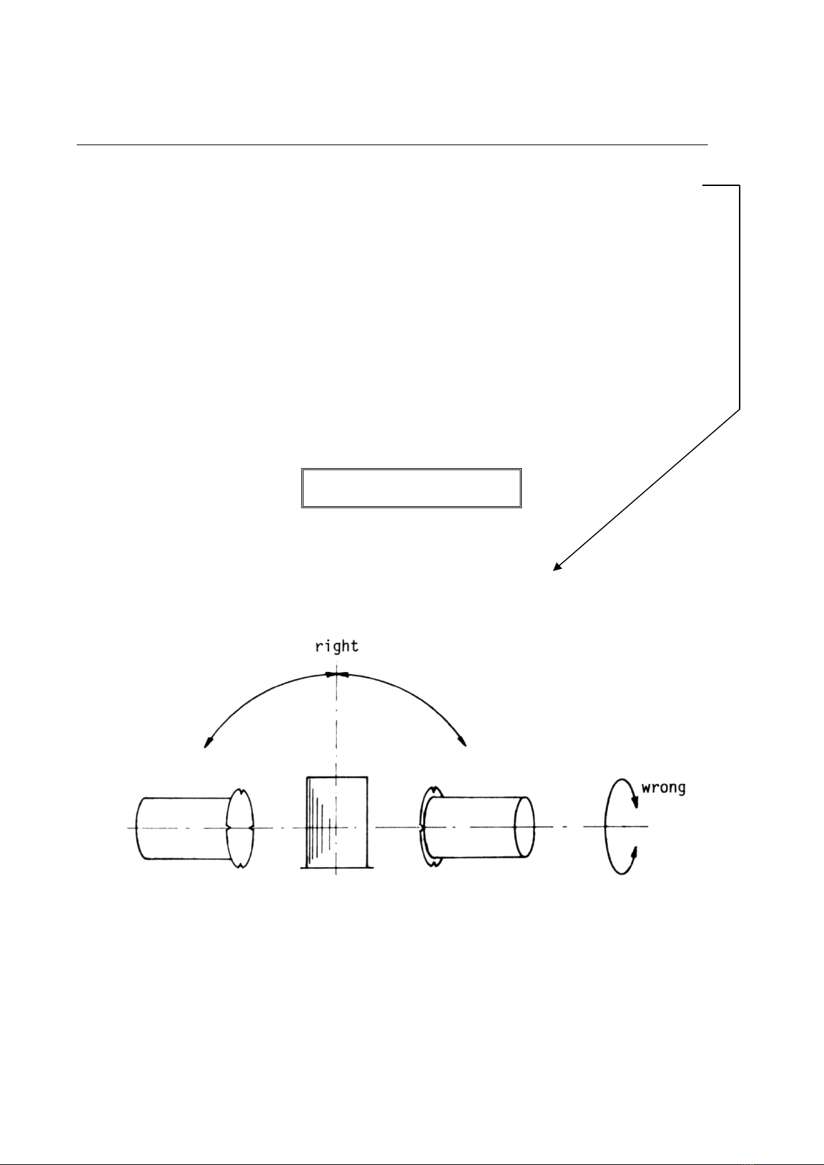
7 Transportation
Do not roll or spin
Rolling or spinning the Hippy, for example when it is being hoisted may damage the
accelerometer beyond repair.
The Hippy should not make more than six revolutions in two minutes.
Spinning may also lead to an entangled suspension of the stabilised platform which causes in
most cases excessive platform tilt.

15
8 Specifications
General8.1
Temperature range: −5 - +35°C (+35 - +55°C, short term, weeks, only, see
also 8.5)
Storage temperature range: −5 - +40°C (+40 - +55°C, short term, weeks, only)
If an instrument is exposed to low temperatures for a
sufficiently long time to reduce the fluid temperature in the
instrument to below –5°C, the fluid will be permanent
altered.
This will result in a reduced natural period time of the
instrument's platform.
Generally repair by Datawell will be possible.
Supply: Junction box terminal no. 1 positive.
Junction box terminal no. 2 negative.
Any voltage between 10 - 30 V DC, 180 mW.
Maximum source impedance 50Ω.
Input capacitance 470 μF.
Maximum permissible voltage between output, battery and
chassis 380 V.
Supply unit is protected against reverse polarity by a series
diode.
Size/weight: See fig. 10.
Housing: Material Stainless Steel AISI316, see fig. 10.
Junction box is drip proof.
Vibration maximum: 4-16 Hz: 1 mm peak, > 16 Hz: 1 g peak.
Humidity: The housing is checked to be watertight with a pressure of
0.5 atmosphere.
To prevent a relative humidity of 100% and condensation,
two 65 gram bags of silicagel are inserted in the
polyethylene bag containing the printed circuit board.
Relative humidity within this bag is indicated by strips
which fades from blue to pink if relative humidity exceeds
40%.

16
Pitch-roll8.2
Output: Pitch : Junction box terminal no. 3.
Roll : Junction box terminal no. 4.
Common : Junction box terminal no. 7.
Loading resistance min. 10 KΩ.
Capacitive loading (cable) max. 0.5 µF.
Output is short circuit protected.
Scale: Output is proportional to the sine of
angle γbetween axis an horizontal plane.
Eu = 10 sinγ(volts) (see fig. 3 *).
Bandwidth: Low pass third order filter;
up to 1 Hz:
amplitude transfer within 1%.
linear phase shift equal to 0.06 seconds.
up to 5 Hz:
within 6 dB.
Scale accuracy: Better than 0.5%.
Maximum relative linearity
error in range −γ1- +γ1 (degrees): γ1/60 (%).
Zero offset: < 0.5°.
Zero stability: After quick rotation around vertical < 1°.
With time, over one year < 0.5°.
Noise: Below 0.05° peak.
*) In case instrument has a non-standard sensitivity see page inserted after cover page.

17
Heave8.3
Output: Heave : Junction box terminal no. 5.
Common : Junction box terminal no. 7.
Loading resistance min. 10 KΩ.
Capacitive loading (cable) max. 0.5 µF.
Scale: 1.0 V/m, maximum range ± 10 m *)
Output at terminal 5 positive going for upward movement of
the sensor.
Position of accelerometer: Approx. 24 cm above bottom plate in centre of cylinder.
The heave (acceleration) of this point is measured.
Scale accuracy (gain error): < 0.5% of measured value after calibration
< 1.0% of measured value after 3 year
Zero offset: Below 30 cm (300 mV), typically 3 cm *)
Zero stability: See under 8.2 "Pitch-roll".
Noise: Below 1 cm peak-peak.
Frequency response: See table below and 2.2.
Period (sec)
Ampl. transfer (%)
Phase shift (degrees)
30
–28.6
+98
20
–8.5
+64.5
15
–3.0
+47
10
–0.7
+30.5
5
+15
2.5
+7.5
The wave amplitudes with frequencies between 0.067 and
0.033 Hz can be corrected within 3% of the true value from
the frequency response, table above.
*) In case instrument has a non standard sensitivity see page inserted after cover page.

18
Acceleration8.4
Output: Acceleration : Junction box terminal no. 6.
Common : Junction box terminal no. 7.
Loading resistance min. 10 KΩ.
Capacitive loading (cable) max. 0.5 µF.
Scale: 1.0 V/m/sec², maximum range ± 10 m/sec² *)
Output at terminal 6 is positive for upward acceleration.
Bandwidth: Low pass third order filter;
up to 1 Hz:
linear phase shift equal to 0.06 sec.
up to 5 Hz:
within 6 dB.
Scale accuracy (gain error): < 0.5% of measured value after calibration
< 1.0% of measured value after 3 year
Zero offset: Below 1 m/sec².
*) In case instrument has a non standard sensitivity see page inserted after cover page.

19
9 System check and calibration (heave)
Simple System check9.1
Connect a recorder with a sensitivity of approximately 2 V to the heave output.
The recorder will show a straight line.
Have two men lift the Hippy several times within 10 sec to a height of about 0.5 m and lower it
without bouncing.
If it bounces the acceleration will be outside the linear range of the accelerometer (10 m/sec²).
When the recorder shows about 0.5 m displacement, the system is working.
Calibration9.2
Heave.
To calibrate the heave meter it is necessary to give the instrument a precisely known vertical
"input" motion.
To avoid the complex problem of relating the time history of input and output to a specification
given in terms of phase, amplitude and frequency this motion should be single frequency.
A low-cost set up that meets these requirements is suspending the Hippy from springs, e.g.
"extenders" that can be bought in a sports shop.
The low mechanical losses of the resulting mass-spring resonant system allow one to maintain a
constant amplitude oscillation with little physical effort.
Also peak acceleration is limited and known.
The period time T is related to the (static) extension length L by:
gLT
2
where g is the acceleration of gravity.
As
g
is very close to
= 3.14, a good approximation is:
LT 2
or the inverse
2
25.0 TL
So, to obtain a period time of 2 seconds the springs should be chosen so that the extension by
the weight of the Hippy is 0.25 x 4 = 1 metre.
It will be clear that the longest period time that can be attained is limited by the height that is
available for the set up.
The acceleration is directly visible, as it is proportional to the spring extension.
In the example for T = 2 seconds the static extension is 1 metre, and that is the extension caused
by the 1 g of gravity.
Thus a 60 cm peak-to-peak motion is a dynamic extension of 30 cm amplitude;
that is 30% of 1 g.
20
10 System check and calibration pitch and roll
Scale: Measure pitch output at pitch angle of +90° and again at pitch angle of −90°.
(Check with plummet if roll axis is vertical within 5°).
The difference of the obtained values has to be: 20 V ± 0.4 V.
The same applies for the roll output at roll angles of + and −90° (pitch axis
vertical).
Zero offset: Zero offset is equal to measured output if instrument is placed on horizontal
plane.
Base plane and top plane are parallel within 0.1°.
So zero offset can be measured with 0.1° accuracy when horizontal top plane is
horizontal (to be checked with water level).
Do not roll instrument
Rotate via upright position
fig. 4
Table of contents


